Table of Contents
Advertisement
Quick Links
Download this manual
See also:
Instruction Manual
INSTALLATION & USER INSTRUCTIONS
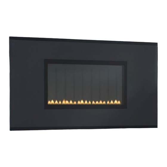
WALL MOUNTED HIGH EFFICIENCY GAS FIRE
Christchurch, Dorset BH23 2BT
Tel: 01202 588 638
Fax: 01202 499 639
www.ekofires.co.uk
e-mail: sales@ekofires.co.uk
Please note : Except where otherwise stated, all rights,
including copyright in the text, images and layout of this
booklet is owned by Focal Point Fires plc. You are not per-
mitted to copy or adapt any of the content without the
prior written permission of Focal Point Fires plc.
MODELS COVERED BY THESE INSTRUCTIONS
5070 GAS FIRE
MODEL SHOWN: EKO 5070 GAS FIRE
1
The products covered by this booklet are protected under
patent GB2275331C.
All instructions must be handed to the user for
safekeeping.
Revision D - 07/16
GB IE
© 2016 Focal Point Fires plc.
Advertisement
Chapters
Table of Contents

Related Manuals for Ekofires EKO 5070


Summary of Contents for Ekofires EKO 5070
- Page 1 Fax: 01202 499 639 www.ekofires.co.uk e-mail: sales@ekofires.co.uk MODEL SHOWN: EKO 5070 GAS FIRE Please note : Except where otherwise stated, all rights, The products covered by this booklet are protected under including copyright in the text, images and layout of this patent GB2275331C.
-
Page 2: Table Of Contents
I N S T A L L A T I O N I N S T R U C T I O N S GB IE Section Contents Page No. Section Contents Page No. Important Notes Testing and Commissioning Appliance Data Operating the Appliance Installation Requirements Setting pressure... -
Page 3: Appliance Data
2.0 APPLIANCE DATA GB IE Operating/Inlet Max Energy Input (kW) Min Energy Input (kW) Pressure (±2.0 mbar) Destination Model Country G25 G30 G31 Gross Gross I 2H Natural gas models 2.35 1.35 GB - IE I 3P LPG models GB - IE 1.38 Specifications Natural Gas Models... -
Page 4: Ventilation
4.0 SITE REQUIREMENTS GB IE (CONTINUED) Clearances to combustible materials Combustible materials are defined as wood, fabrics, or other materials likely to combust if exposed to flame. Generally, any mate- rial, which is likely to discolour, melt or misshape when exposed to moderate heat, should be considered as a combustible mate- rial or surface. -
Page 5: Gas Supply Routes
6.0 GAS SUPPLY ROUTES GB IE There are six possible entry points for the gas supply pipework to enter the appliance firebox. as shown in figure 2. These entry points are ‘knock out’ type holes. Non-concealed gas con- nections may be made using the entry points in the bottom or sides of the firebox. -
Page 6: Testing And Commissioning
7.0 FIXING THE APPLIANCE GB IE (CONTINUED) Do not tighten fully. Before tightening the wall mounting screws fully, at this stage it is recommended to check the horizontal alignment of the appliance with a spirit level, as small adjustments can still be made if necessary. -
Page 7: Fitting The Decorative Frame
8.3 FITTING THE DECORATIVE FRAME ASSEMBLY GB IE Remove the glass facia panel from any protective packaging. The Figure 9 glass facia panel is supported by four M6 screws which protrude from the front of the outer casing. Ensure each screw is unscrewed approximately one turn from the fully screwed in position in order to create a 2mm gap (shown in figure 10). -
Page 8: Servicing The Burner Unit
10.1 SERVICING THE BURNER UNIT AND GAS ASSEMBLY GB IE Firstly, remove the decorative facia assembly as described in section 8.4. Remove the inner glass panel, and disconnect the gas connection inside appliance.The gas connections to the gas valve can now be released. Undo the four screws retaining the burner support brackets to the base and rear of the firebox, and remove the control knob and spindle assembly by removal of the spindle retaining clip.The burner may now be removed. -
Page 9: Troubleshooting Guide
11.0 TROUBLESHOOTING GUIDE GB IE • No gas to fire, check isolators are open and gas supply is on. Fire sparks but pilot does not light • Pipework blockage, clean out. • Air not fully purged, re purge supply or wait longer. •... -
Page 10: Outlet Openings
U S E R I N S T R U C T I O N S GB IE Section Content Page No Important Notes Clearances to Combustibles Fire guards Ventilation & Room Size Operating Instructions Combustion Monitoring System Cleaning Servicing List of Replacement Parts 10.0 Installation Details... -
Page 11: Clearances To Combustibles
2.0 CLEARANCES TO COMBUSTIBLES - GB IE (CONTINUED) Clearances to combustible materials (continued) Under no circumstances should any electrical equipment e.g. plasma/LCD screen TV sets etc. be positioned on the wall above the appliance.The appliance is designed to be wall mounted alone and not in conjunction with any type of combustible fire surround. No combustible shelves should be positioned on the wall above the appliance. -
Page 12: Combustion Monitoring System
5.0 OPERATING THE APPLIANCE GB IE The control knob is located on the lower right hand side of the outer case. It is marked as shown in figure 4. Push the control knob in fully and turn anti- The pilot is visible behind the left hand side of the burner. ‘OFF’... -
Page 13: Installation Details
10.0 INSTALLATION DETAILS GB IE Name & contact details of installer : Supplied by : Installer GAS SAFE registration No : Model : Fire serial No. : Date installed : 11.0 SERVICE HISTORY Date of service Serviced by (name): GAS SAFE No. : Contact details of Engineer ©... - Page 14 3G Service Department to the address below. Alternatively, you can email or fax. EKO Fires, 3G Service Department, Reid Street, Christchurch, Dorset, BH23 2BT. Email: service@ekofires.co.uk Fax. 01202 499326. Details required: 1. Name, full address including postal code and contact telephone number.
- Page 15 EKO Fires L30 Flueless Gas Fire ENERGIA · · ΕΝΕΡΓΕΙΑ · ENERGIJA · ENERGY · ENERGIE 2015/1186...
- Page 16 Product Fiche Supplier's name or trademark; EKO Fires Model identifier; L30 Flueless Gas Fire Gas Category/Pressure = I (20) Energy Efficiency Class of the model; A Direct heat output; 2.3 kW Indirect heat output; N.A. Energy Efficiency Index; 91 Useful Energy Efficiency at nominal heat output; 100% Useful Energy Efficiency at minimum load; 100% Specific precautions that shall be taken when the local space heater is assembled, installed or maintained; This appliance must be installed, commissioned and maintained by a competent person. Prior to installation the competent person must ensure that the local distribution conditions (identification of the type of gas and pressure) and adjustment of the appliance are compatible. This appliance must be installed in accordance with the rules in force, and used only in a sufficiently ventilated space of adequate volume. Consult the instructions before installation and use of this appliance. The competent person must refer to and comply with the specific instructions listed in the Installation Manual before starting to install and commission the appliance. ...
- Page 17 Table 1 Information requirements for gaseous/liquid fuel local space heaters L30 Flueless Gas Fire Model identifier(s): [yes/no] Indirect heating functionality: (kW) Direct heat output: N.A. Indirect heat output: Fuel Space heating emissions(*) Select fuel type [gaseous/liquid] [specify] [mg/kWh (GCV) input Gaseous Natural Gas < 130 t.b.c. Item Symbol Value Unit Item Symbol ...
- Page 18 LPG L30 Flueless Gas EKO Fires Fire ENERGIA · · ΕΝΕΡΓΕΙΑ · ENERGIJA · ENERGY · ENERGIE 2015/1186...
- Page 19 Product Fiche Supplier's name or trademark; EKO Fires Model identifier; L30 Flueless Gas Fire Gas Category/Pressure = I (37) Energy Efficiency Class of the model; A Direct heat output; 2.0 kW Indirect heat output; N.A. Energy Efficiency Index; 91 Useful Energy Efficiency at nominal heat output; 100% Useful Energy Efficiency at minimum load; 100% Specific precautions that shall be taken when the local space heater is assembled, installed or maintained; This appliance must be installed, commissioned and maintained by a competent person. Prior to installation the competent person must ensure that the local distribution conditions (identification of the type of gas and pressure) and adjustment of the appliance are compatible. This appliance must be installed in accordance with the rules in force, and used only in a sufficiently ventilated space of adequate volume. Consult the instructions before installation and use of this appliance. The competent person must refer to and comply with the specific instructions listed in the Installation Manual before starting to install and commission the appliance. ...
- Page 20 Table 1 Information requirements for gaseous/liquid fuel local space heaters L30 Flueless Gas Fire ‐ LPG Model identifier(s): [yes/no] Indirect heating functionality: (kW) Direct heat output: N.A. Indirect heat output: Fuel Space heating emissions(*) Select fuel type [gaseous/liquid] [specify] [mg/kWh (GCV) input Gaseous Propane < 130 t.b.c. Item Symbol Value Unit Item Symbol ...
Need help?
Do you have a question about the EKO 5070 and is the answer not in the manual?
Questions and answers