Table of Contents
Advertisement
Quick Links
INSTALLATION & USER INSTRUCTIONS
Christchurch, Dorset BH23 2BT
Tel: 01202 588 638
Fax: 01202 499 639
www.ekofires.co.uk
e-mail: sales@ekofires.co.uk
PLEASE NOTE: EKO 4010, 4015, 4020 & 4025 HIGH EFFICIENCY GAS FIRES MAY BE SUPPLIED WITH
The products covered by this booklet are protected under patent GB2356698B
IN THE UK ALWAYS USE A GAS SAFE REGISTERED ENGINEER TO INSTALL, REPAIR OR SERVICE THIS APPLIANCE
Please note : Except where otherwise stated, all rights,
including copyright in the text, images and layout of this
booklet is owned by Focal Point Fires plc. You are not per-
mitted to copy or adapt any of the content without the
prior written permission of Focal Point Fires plc.
HIGH EFFICIENCY GAS FIRE
MODELS COVERED BY THESE INSTRUCTIONS
4010, 4015, 4020 & 4025 HIGH EFFICIENCY GAS FIRES
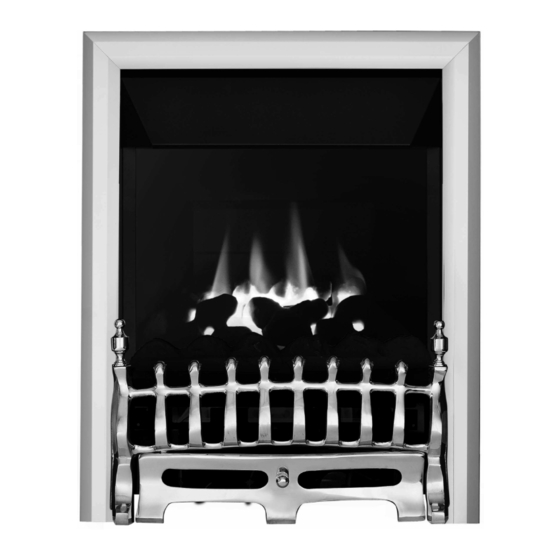
MODEL SHOWN: EKO 4010 HE GAS FIRE
DIFFERENT FRETS THAN SHOWN
All instructions must be handed to the user
for safekeeping.
1
GB IE
BS7977-1 : 2009
KM579168
Revision H - 01/14
© 2014 Focal Point Fires plc
Advertisement
Table of Contents

Subscribe to Our Youtube Channel
Related Manuals for Ekofires EKO 4010 HE


Summary of Contents for Ekofires EKO 4010 HE
- Page 1 BS7977-1 : 2009 KM579168 MODEL SHOWN: EKO 4010 HE GAS FIRE PLEASE NOTE: EKO 4010, 4015, 4020 & 4025 HIGH EFFICIENCY GAS FIRES MAY BE SUPPLIED WITH DIFFERENT FRETS THAN SHOWN The products covered by this booklet are protected under patent GB2356698B...
-
Page 2: Table Of Contents
GB IE I N S T A L L A T I O N I N S T R U C T I O N S Section Page No. Section Contents Contents Page No. Important Notes Fitting the Burner Appliance Data FinalAssembly,T esting and Commissioning Installation Requirements Spark Gap... -
Page 3: Appliance Data
GB IE 2.0 APPLIANCE DATA Inlet/Operating Max Energy Input Min Energy Input Destination Pressure (±2.0 mbar) (kW) (kW) Control Type Countries G20 G25 G30 G31 Gross Gross Manual GB/IE 3.15 Slide GB/IE 3.15 Specifications Manual Control Models Slide Control Models Efficiency 90% (net), 81% (gross) 90% (net), 81% (gross) -
Page 4: Debris Collection Space
GB IE 4.0 SITE REQUIREMENTS (continued) This appliance requires a natural draught flue system which may be one of the following; 225mm x 225mm (9in x 9in) brick or stone. 125mm (5in) minimum diameter lined brick or stone. 125mm (5in) minimum diameter twin wall flue conforming to BS 715. Pre-cast block flue complying with BS 1289 or BS EN 1858. -
Page 5: Ventilation
GB IE 5.0 VENTILATION No purpose provided ventilation is normally required for this appliance.The requirements of other appliances operating in the same room or space must be taken into consideration when assessing ventilation. If spillage is detected when commissioning the appliance, then amongst other problems there may be insufficient natural ventilation for correct operation of the flue. -
Page 6: Preparing The Appliance
GB IE 8.0 PREPARING THE APPLIANCE The fireplace opening and environment must be in compliance with specifications laid Figure 3 down in the appropriate sections of these instructions. Remove the appliance from it’s car- ton as described previously and stand upon a dust sheet or similar. Place the decorative frame, coals, ceramics and fixings safely to one side. -
Page 7: Cable Fixing
GB IE 8.3 CABLE FIXING Figure 8 Thread both tensioning cables through the holes at the top of Cable Route the firebox, both eyelets, and back through the lower holes in 2. Hold tensioner steady the firebox in the positions indicated in figure 7. Push the appliance back into the fireplace, centralise and pull the loose cables through the holes into the firebox. -
Page 8: Final Assembly
GB IE 9.3 FINAL ASSEMBLY Glass Panel : Refit the glass panel ensuring that the unsupported edge of the glass is facing downwards. Take care not to damage the ceramic fuel bed when fitting. Secure using four M6 screws previous- ly removed. -
Page 9: Operating The Appliance - Slide Control
9.5 OPERATING THE APPLIANCE GB IE - SLIDE CONTROL MODELS Figure 17 The pilot is visible through the viewing hole which is located at the lower left hand side of the fuel bed. Push the slide control knob fully downwards to the SPARK position, and hold there for approximately ten seconds. -
Page 10: Testing For Spillage
9.8 TESTING FOR SPILLAGE GB IE Close all doors and windows to the room containing the appliance. Let the fire run on HIGH for five minutes.Take a smoke match and put in the smoke match tube provided. Light the smoke match and position the end of the smoke match tube centrally next to the draught diverter as shown in figures 19 and 20. -
Page 11: Troubleshooting Guide
GB IE 11.1 CLEANING THE CERAMIC PARTS Remove the firefront and place to one side. Remove the ceramic components. Gently clean in the open air. Be careful not to create dust from the coals.Where necessary replace damaged components with genuine spares. Seal scrap ceramic components in plastic bags and dispose at proper refuse sites as directed. -
Page 12: Troubleshooting Guide (Continued)
12.0 TROUBLESHOOTING GUIDE (continued) GB IE • Loose or faulty thermocouple, rectify. Fire runs for a time • Blocked pilot, clean out. and then cuts off • Excessive drafts in the room. • Excessive flue pull. • Fire is too close to an air vent. •... - Page 13 GB IE U S E R S I N S T R U C T I O N S Section Contents Page No. Important Notes Firefront Clearances To Combustibles Fire Guards Servicing Ventilation Operating The Appliance - Manual Control Models Operating The Appliance - Slide Control Models Flue Spillage Monitoring System Cleaning...
- Page 14 GB IE 4.0 FIRE GUARDS The fireguards specified in BS 8423 are intended to protect people from falling into a fire, prevent burns and reduce the risk of injury, particularly to young children and the infirm. In addition it is intended to reduce the risk of fire resulting from clothing and/or other flam- mable materials coming into contact with, or in proximity to, burning fuel and/or hot surfaces.
- Page 15 7.1 OPERATING THE APPLIANCE GB IE - SLIDE CONTROL MODELS Figure 4 The pilot is visible through the viewing hole which is located at the lower left hand side of the fuel bed. Push the slide control knob fully downwards to the SPARK position, and hold there for approximately ten seconds.
- Page 16 GB IE 10.0 FUEL BED LAYOUT - CONTINUED Figure 5 4. Place the moulded coal piece marked on the underside ‘C’ onto the matrix as shown in figure 5 Figure 6 5. Place the moulded coal piece marked on the underside ‘D’...
- Page 17 14.0 INSTALLATION DETAILS GB IE Model : Installer GAS SAFE registration no. : Date installed : Fire serial No. : Name & contact details of installer : Supplied by : 15.0 SERVICE HISTORY Date of service Serviced by (name): GAS SAFE No. : Contact details of Engineer ©...
- Page 18 Eko Fires ltd, 3G Service Department, Reid Street, Christchurch, Dorset, BH23 2BT. Alternatively email: service@ekofires.co.uk or fax. 01202 499326. Details required: 1. Name, full address including post code and contact telephone number.
Need help?
Do you have a question about the EKO 4010 HE and is the answer not in the manual?
Questions and answers