Table of Contents
Advertisement
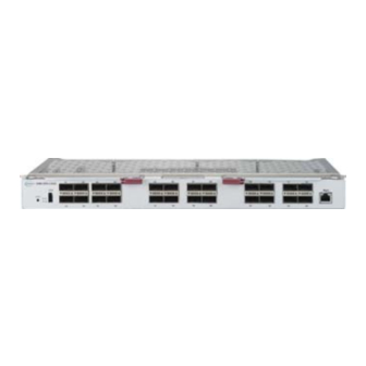
8U/4U SuperBlade
Network System Options
MBM-XEM-002 10 Gbps
Ethernet Switch Module
MBM-GEM-004 1 Gbps
Ethernet Switch Module
SBM-OPH-C4020
Omni-Path Architecture (OPA)
100-Gbps Ethernet Switch Module
User's Manual
Revison 1.0
™
MBM-XEM-001 10 Gbps
Ethernet Switch Module
MBM-GEM-001 2.5-Gbps/1 Gbps
Ethernet Switch Module
SBM-IBS-E3616
InfiniBand
100-Gbps Ethernet Switch Module
Advertisement
Table of Contents


Need help?
Do you have a question about the SuperBlade MBM-XEM-002 and is the answer not in the manual?
Questions and answers