Inter-Tel ECX 2000 Installation & Maintenance Manual
Hide thumbs
Also See for ECX 2000:
- Installation and maintenance manual (142 pages) ,
- Administrator's manual (109 pages)
Table of Contents
Advertisement
Advertisement
Table of Contents

Subscribe to Our Youtube Channel
Related Manuals for Inter-Tel ECX 2000


Summary of Contents for Inter-Tel ECX 2000
-
Page 2: Table Of Contents
INE MODULE EXTERNAL MUSIC-ON-HOLD MODULE......................29 T1 MODULE (FUTURE DEVELOPMENT)......................29 CONNECTING THE BATTERY-BACKUP-UNIT (BBU) TO THE SYSTEM..........30 CONNECTING THE BATTERY ........................... 31 EXTENSIONS................................32 ECX 2000 ........................32 DIGITAL TELEPHONE SET ECX 1000/ ECX 1000W ......................33 DIGITAL TELEPHONE (DSS) ........................ - Page 3 EncoreCX Installation & Maintenance Manual CABLING THE UNIT ............................. 39 ..........................40 ONNECTING THE EXTENSIONS ..............................41 CONNECTIONS ................................41 HONE ................................41 OORSTRIKE PA (P ....................41 ONNECTING A UBLIC DDRESS AMPLIFIER ..................... 41 ONNECTING A RINTER TO THE ERIAL MDF C ......................
-
Page 4: Fcc Regulations
EncoreCX Installation & Maintenance Manual FCC Regulations Important This equipment complies with Part 68 of FCC rules. Customers connecting this equipment to the telephone network shall, before such connection is made, give notice to the telephone company of the particular line(s) to which such connection is to be made, and shall provide the telephone company with the following information: —... - Page 5 EncoreCX Installation & Maintenance Manual If trouble is experienced with this equipment, contact a local service representative for repairs and/or warranty information. The customer, users, and unauthorized technicians should not repair, make adjustments to, or attempt to service this equipment in any way. In the event of trouble with the telephone line(s), this equipment must be disconnected from the telephone line(s).
- Page 6 The user may find the following booklet prepared by the FCC helpful: “How to Identify and Resolve Radio-TV Interference Problems” This booklet is available from the U.S. Government Printing Office, Washington, D.C. 20402, Stock No. 004-000-00398-5. If RFI problems persist, contact Inter-Tel Customer Support.
-
Page 7: Safety Regulations
EncoreCX Installation & Maintenance Manual Safety Regulations Important Safety Instructions The following safety information is reprinted from UL 1459. When using your telephone equipment, basic safety precautions should always be followed to reduce the risk of fire, electric shock, and injury to persons, including the following: Read and understand all instructions. - Page 8 EncoreCX Installation & Maintenance Manual · If the product exhibits a distinct change in performance. Avoid using a telephone (other than a cordless type) during an electrical storm. There may be a remote risk of electric shock from lightning. Do not use the telephone to report a gas leak if the telephone is in the vicinity of the leak. Save These Instructions...
-
Page 9: Limited Warranty
Installation & Maintenance Manual Limited Warranty For a period of 18 months from the date of purchase, INTER-TEL warrants the Equipment (except for fuses and lamps) to be free from defects in material, workmanship, or both, and to comply with specifications for the Equipment, as set forth in the Installation Manual. -
Page 10: Software License Agreement
“Company” or “Inter-Tel”) that operates by means of the Software. “Authorized Dealer” means an individual or entity currently authorized in writing by agreement and in good standing with Inter-Tel entitling the dealer to sell or license the specific Software covered by this license. “Software” means: the computer programs accompanying this... - Page 11 (2) prohibit the right of resale and/or relicensing of the software without the express written consent of Inter-Tel. You agree that your failure to properly sublicense the software to an end user will subject you to responsibility for the losses occasioned to Inter-Tel.
- Page 12 This Agreement shall be governed by the laws of the State of Arizona. No failure or delay on the part of Inter-Tel to enforce its rights hereunder shall operate as a waiver of any right.
-
Page 13: Introduction
"The EncoreCX is a hybrid PABX/key-system, which may be equipped with digital telephone sets (ECX 1000, ECX 1000W or ECX 2000) or standard two-wire DTMF telephones such as the ECX 100 analog telephone. Extensions can also be equipped with fax or answering machines. -
Page 14: Electrostatic Precaution (Esp)
618.6000 ECX 1000W Digital Telephone, Pedestal, Line telephone Cord, 3 Key Templates, Color white ECX 2000 digital 618.5020 ECX 2000 Telephone, Pedestal, Phone Power telephone Supply, Line Cord, 3 Key Templates, Color gray DSS add on module 618.5008 DSS, Pedestal, Wall Mount Bracket,... - Page 15 EncoreCX Installation & Maintenance Manual Maintenance Items CCU Extension Card 618.5026 Replacement card for the extension card in the CCU main print circuit 618.5024 Replacement for the main control PCB in the CCU board CCU MDF print circuit 618.5025 Replacement for the CCU MDF board System power supply - PCB 618.5023...
-
Page 16: Installation Steps
EncoreCX Installation and Maintenance Manual Installation steps Carry out the following steps to install the system: FIRST, read the safety and precaution information on page 12 carefully. SECOND, mount the Main Equipment as detailed in the section starting on page 16. THIRD, install the CO line and expansion modules as required. -
Page 17: Installing The Main Equipment
EncoreCX Installation & Maintenance Manual Installing the main equipment Equipment location The equipment is intended for installation in a residential or office-type environment. It needs to be mounted at a convenient working height on a dry, flat wall. The normal height is 5 feet from the floor to the bottom of the case. - Page 18 EncoreCX Installation and Maintenance Manual CCU Mounting bracket clearances The main unit is mounted on a wall using the bracket supplied and should have top and side clearance as shown below. CCU Mounting Bracket 300mm min If the system is to be equipped with an Extension or Internet Router module, then two mounting brackets need to be installed.
- Page 19 EncoreCX Installation & Maintenance Manual Mounting the CCU The CCU is mounted on the bracket by sliding it on from the left-hand side. The marks on the side of the CCU must be lined up with the flanges on the wall bracket as shown below before sliding the CCU into place.
-
Page 20: Modules Located In The Ccu
EncoreCX Installation and Maintenance Manual Modules located in the CCU There are a number of modules that can be installed in the CCU. · CO Line Module (Colored Black). This provides two CO lines. Up to two of these modules can be installed in the CCU to provide two or four CO lines. -
Page 21: System Expansion
EncoreCX Installation & Maintenance Manual System Expansion To equip the switch with more than eight extensions, two CO Line Modules or to add an Internet Router Module, a backplane, mounted on a second wall bracket, is needed. The power must be disconnected to install the backplane or expansion modules. Installing the Backplane wall bracket The CCU and backplane brackets are identical. -
Page 22: Mounting The Backplane
EncoreCX Installation and Maintenance Manual Mounting the Backplane Slide the backplane on from the right-hand side. Ensure the connector is fully mated with the CCU. Securing the backplane to the wall bracket A mounting screw is used to securely locate the backplane on the wall bracket. This provides additional rigidity to ensure the backplane and CCU connectors do not move. -
Page 23: Expansion Modules
EncoreCX Installation & Maintenance Manual Expansion modules There are two types of expansion modules that can be installed on the backplane. These are the Extension module and the Internet module. These modules are installed in the same way. The Extension Module is also equipped with two connectors for the CO Line modules. The power must be disconnected when installing the backplane or expansion modules. -
Page 24: Removing The 008 Module From The Backplane
EncoreCX Installation and Maintenance Manual Removing the 008 module from the backplane 1. Unlock the upper locking screw by turning the locking screw, with a suitable screwdriver, ¼ turn counterclockwise. 2. Lift the cover. 3. Unlock the Extension module locking screw by turning the locking screw, with a suitable screwdriver, ¼... -
Page 25: Installing An Expansion Module
EncoreCX Installation & Maintenance Manual 3. Gently push the 008 module onto the MDF. 4. Lock the 008 module in place by turning the locking screw ¼ turn clockwise with a suitable screwdriver. Installing an expansion module Install the backplane as described on page 21. Install the MDF in the first free left-hand slot on the backplane. -
Page 26: Co Line Module
EncoreCX Installation and Maintenance Manual CO Line module The CO Line module contains circuitry for two CO lines. The module is colored BLACK and it can be installed in the CCU and also on the expansion module. Note: There is an arrow on the module, which indicates the orientation of the card in the slot. The arrow always points up. - Page 27 EncoreCX Installation & Maintenance Manual First CO Line module position Remove the cover. Locate the module Note: There is an arrow located on the module to indicate the orientation of the card.
- Page 28 EncoreCX Installation and Maintenance Manual Termination in CCU All extension and line cabling is terminated on the CCU with RJ11 connectors. Similarly, all line and extension cabling is terminated on the Extension modules with RJ11 connectors.
- Page 29 EncoreCX Installation & Maintenance Manual Voice Mail module (Optional) The Voice Mail module is colored BLUE. It is positioned in the Voice Mail module slot in the CCU. There are three versions; two-port with five hours capacity, four-port with 10 hours capacity and eight-port with 20 hours capacity.
-
Page 30: External Music-On-Hold Module
EncoreCX Installation and Maintenance Manual External Music-on-Hold module The external Music-On-Hold module is supplied with a stereo jack for the input from the external source and a cable to connect to an extension position. The extension that is to be used as the external Music-On- Hold source is selected in System Programming. -
Page 31: Connecting The Battery-Backup-Unit (Bbu) To The System
EncoreCX Installation & Maintenance Manual Connecting the Battery-Backup-Unit (BBU) to the system The battery back up provides full operation of the system for approximately one hour in the event of a power failure. The battery will support 11 erlangs of voice traffic for 1 hour. An erlang is a measure of telephony traffic. -
Page 32: Connecting The Battery
EncoreCX Installation and Maintenance Manual Connecting the battery Ensure the battery switch on the BBU unit is turned off. This switch does not turn off the main supply. The main AC power source is disconnected by unplugging the main cord. ·... -
Page 33: Extensions
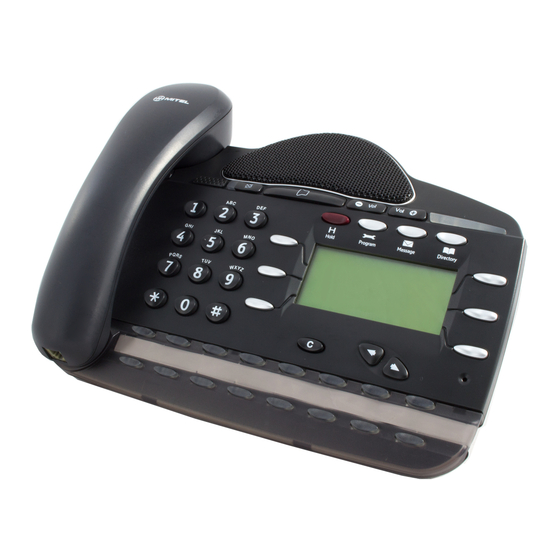
EncoreCX Installation & Maintenance Manual Extensions ECX 2000 digital telephone set ECX 2000 connections (underside of phone) All ECX 2000 digital telephone sets are supplied with a 5V DC Power transformer. DSS socket Handset connector Line cord connector Data Port... -
Page 34: Ecx 1000/ Ecx 1000W Digital Telephone
EncoreCX Installation and Maintenance Manual ECX 1000/ ECX 1000W digital telephone ECX 1000/ ECX 1000W digital telephone connections (underside of phone) Handset connector Line cord connector Text port only. No user functionality Data Port Headset Port... - Page 35 EncoreCX Installation & Maintenance Manual Attaching the digital telephone desk pedestal (ECX 1000/ECX 1000W and ECX 2000) Wall mount Plinth position Pedestal position 35° Pedestal position 20 ° Text port only. No user functionality Position at 35 degrees Position at 20 degrees...
-
Page 36: Direct Station Selection (Dss) Unit
To connect the DSS unit to an ECX 2000 digital telephone (ECX 2000 only) Use the six-inch cord to connect the DSS to the base of the ECX 2000 digital telephone. The DSS connector is marked on the base of the telephone. - Page 37 EncoreCX Installation & Maintenance Manual Clip, Pedestal and installation of the DSS Cord Rail 6" cord (RJ11 connector) NOTE: For the 20 degrees position or the 35 degrees position, refer to page...
-
Page 38: Wall-Mounting An Ecx 1000 Or Ecx 2000 Telephone
EncoreCX Installation and Maintenance Manual Wall-mounting an ECX 1000 or ECX 2000 telephone The phone pedestal is inverted on the base to wall mount the phone. Locate, drill and plug the two screw locations as shown below. The holes should be deep enough to accept a one-inch screw. -
Page 39: Door Phone
EncoreCX Installation & Maintenance Manual Wall hook when the ECX 1000/ECX 2000 is in a 20 degrees or 35 degrees position Wall hook when the ECX 1000/ECX 2000 is wall mounted Door Phone The door extension is connected to extension 23, the fourth extension on the CCU. -
Page 40: Cabling The Unit
EncoreCX Installation and Maintenance Manual Cabling the unit All the extensions and lines are connected to the switch by RJ11 connectors located in the MDF areas. RJ11 connectors or optional patch panel with RJ11 type connections should be mounted or placed less than 7' of the CCU to facilitate using standard modular cables of 7' in length. -
Page 41: Connecting The Extensions
EncoreCX Installation & Maintenance Manual Connecting the extensions It is recommended that all extensions be cabled with two pairs. The ECX 1000 series telephones and ECX 2000 digital telephones use all four wires and standard phones use the AB pair only. Do not exceed the following resistance or distance limits when connecting extensions to the System Unit. -
Page 42: Ccu Connections
EncoreCX Installation and Maintenance Manual CCU connections The CCU has the following connectors: · Eight RJ11 connectors for the extensions · Four RJ11 connectors for the CO lines · An RJ45 for the T1 (Future development) · One RJ11 connector for serial interface RS 232 ·... -
Page 43: Extension Module Mdf Connections
EncoreCX Installation & Maintenance Manual Connect the cord to the four-way RJ11 connector on the CCU. Connect to the PC using either the six-way RJ plug or the cord and DB9 converter as required. The pinouts from the RS 232 interface of the DB9 to the RJ11 are: DB9 connector RJ11 plug Extension Module MDF Connections... -
Page 44: Internet Router Module Connections
EncoreCX Installation and Maintenance Manual Internet Router Module connections The Internet Router module has four RJ45 connectors providing four 10/100 Base T Extension for an Internal LAN and a connection for the DSL modem via a 10 Base-T WAN RJ45 connector. See page 54 for basic Internet Router module programming. -
Page 45: Central Bell
EncoreCX Installation & Maintenance Manual Central Bell If a central bell is required, connect it to a spare extension position and include the extension in the Ringing Groups that require the bell. Expanding an existing system Modules may be removed and re-inserted in a system without disconnecting the power. See page 45. However, if additional modules are being installed in a working system, it is necessary to power the system down before installing a module or backplane. -
Page 46: Maintenance Procedures
EncoreCX Installation and Maintenance Manual Maintenance procedures Faults can be rectified on-site by replacing faulty modules or PCBs (Printed Circuit Boards). Hot swapping faulty modules The CO Line modules can be replaced without powering the system down. · The CO Line modules can be removed and replaced without powering down the system. ·... -
Page 47: Replacing A Faulty Module Mdf
EncoreCX Installation & Maintenance Manual Replacing a faulty module MDF To replace a faulty MDF of a Extension or Internet Router module, the procedure is: Remove the cabling from the MDF, ensuring the cables are correctly tagged so they can be readily reinstalled. -
Page 48: Replacing Faulty Pcbs
EncoreCX Installation and Maintenance Manual Replacing faulty PCBs Replacing the 008 extension board If a fault occurs on the first eight extensions, the 008 extension PCB must be replaced. This PCB is NOT hot swappable. The system must be powered down to change this board. - Page 49 EncoreCX Installation & Maintenance Manual REPLACING THE CCU CONTROL PCB This PCB is NOT hot swappable. The system must be powered down to change this board. Electrostatic precautions must be made when replacing this board. Connect to the ESD pillar on the CCU before removing the CCU cover. The procedure to be used when replacing the CCU control PCB is: If a battery is installed, turn off the switch.
-
Page 50: Power Supply Unit Spare Fuse
EncoreCX Installation and Maintenance Manual Power supply unit spare fuse A spare fuse is located in the power supply unit. It is in a holder directly below the installed fuse. If there is no power being supplied to the unit, check if the fuse is blown using the following procedure: 1. -
Page 51: Replacing The Ccu Mdf
EncoreCX Installation & Maintenance Manual Replacing the CCU MDF This PCB is NOT hot swappable. The system must be powered down to change this board. Electrostatic precautions must be made when replacing this board. Connect to the ESD pillar on the CCU before removing the CCU cover. The procedure to be used when replacing the CCU MDF unit is: Power the system down by unplugging it at the main AC power source. -
Page 52: Power Failure
The connectors can be wired to separate standard telephones or paralleled with extensions equipped with standard phones. ECX 2000 and ECX 1000 digital telephones cannot be used as power failure phones. All power failure phones must be standard DTMF telephone sets such as the ECX... -
Page 53: Switch On
· Make sure the Power LED is continuously lit. This is the third LED in the CCU MDF area. Getting Started Remove any anti-scratch protective film from the ECX 1000 and ECX 2000 digital telephone LCDs (Liquid Crystal Display). Label all digital telephone programmable keys and other telephones. -
Page 54: Programming
EncoreCX Installation and Maintenance Manual Programming Essential programming is carried out either from a digital telephone set connected to extension 20 or via the Programming and Maintenance software on the programming PC. Ensure that the following programming is done. Equipped CO lines The system assumes that all line cards have lines connected to them. -
Page 55: Internet Router Programming
EncoreCX Installation & Maintenance Manual Class 6 is the additional restriction codes in the “Restricted Table” in Class codes programming. These can be combined with Classes 1, 2 and 3. Internet Router programming The Internet Router module can only be programmed from the Programming and Maintenance software package running on a PC connected to the serial interface. -
Page 56: Dsl
EncoreCX Installation and Maintenance Manual The following screen is displayed when installation wizard is selected. · Enter the Username. This will be provided by the ISP. · Enter the Password. This will be provided by the ISP. · Select either PPPoE or IP. Details of this will be provided by the ISP. ·... -
Page 57: Recommendations For Customer Training
The customer may wish to use the 30 minutes to explain a selection of other features, such as: · Call transferring capabilities · Programming ECX 1000, ECX 1000W and ECX 2000 keys · Time and date programming · System and or personal speed-dial programming ·... -
Page 58: Troubleshooting
EncoreCX Installation and Maintenance Manual Troubleshooting All faults can normally be traced quite readily to a particular PCB. Before replacing any PCB, fault conditions should be checked to see if programming or mis-operation causes them. The digital telephone display will often indicate which system features have been set. System not initializing Check that all system cards have been properly installed, with all connectors fully located. -
Page 59: Technical Specification
Max 40 Standard DTMF Telephones Max 40 ECX 1000 digital telephone set 8-key digital telephone set Terminals Max 40 ECX 2000 digital telephone set 16-key digital telephone set Max 8 DSS – Additional 32 programmable keys Extension capacity Digital telephone set capacity... - Page 60 EncoreCX Installation and Maintenance Manual Call recalling 1s on 400 ms off, 400 ms on 1.2 s off Tone frequencies 440 Hz ±5 Hz, unless stated otherwise Dial Tone Continuous tone of 440 Hz ±5% and 350 Hz ±5% combined Special dial tone 800 ms on 800 ms off of 440 Hz ±5% and 350 Hz ±5% combined...
-
Page 61: Index
FCC Regulations, 3 35 degrees, 34 Digital Telephone plinth, 34 Additional modules, 44 Digital telephone wall-mounting, 37 Additional Modules, 44 ECX 2000 connections, 32 DSL, 15, 54 Getting Started, 52 Analogue Lines, 42 Hot Swapping, 45 backplane, 21 Incoming ringing, 53... - Page 62 EncoreCX Installation and Maintenance Manual Issue 1, October 2003 Part No. 618.5047...
Need help?
Do you have a question about the ECX 2000 and is the answer not in the manual?
Questions and answers
We changed our voicemail message and when you hear it from the greeting it has been changed but when you call in it is still the old greeting..HELP
The voicemail greeting on the Inter-Tel ECX 2000 may still be the old message after changing it because the system retains voicemail greetings and messages after a new system program is flashed. To ensure the new greeting is applied, the system and voicemail may need sufficient time to reset properly. Additionally, the updated greeting should be correctly stored and retrieved using the VM Backup \ Restore Manager in the System drop-down menu of the Maintenance and Programming Software application.
This answer is automatically generated