Table of Contents
Advertisement
Quick Links
Advertisement
Table of Contents
Troubleshooting

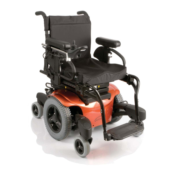
Related Manuals for Quickie QM-7 Series


Summary of Contents for Quickie QM-7 Series
- Page 1 Quickie QM-7 Series Service Manual ©2012 Sunrise Medical Inc. 120938 Rev B...
-
Page 2: Table Of Contents
Quickie QM-7 Series Service Manual Contents Nine Bars - Solenoid Brake Trip Introduction and Basic Setup Ten Bars - High Battery Voltage Motor - Drive Gear engaged Battery Fault Motor - Free-wheel Section 4 Section 1 R-net Troubleshooting Multimeter Tutorial... - Page 3 This Service Manual is intended as a troubleshooting guide for the Quickie QM-7 Series of products. Photographs and content may differ from the actual products in some cases due to changes in specifications and other factors.
-
Page 4: Motor - Drive Gear Engaged
Input device? (normally Joystick) b. Cable from Joystick to the Bus Line c. Control Module; for the QM-7 series located at back of chair behind shroud d. Are batteries installed correctly? (refer to Section 1 of this manual □ Are all necessary connections fastened and fully engaged? a. -
Page 5: Multimeter Tutorial
“fused”, so that you don’t end up melting the meter’s circuits. 4. Current up to 10A. Same as above, except it can take more cur- Fig. 3.3 rent, as the name suggests. SUNRISE MEDICAL QM-7 SERIES SERVICE MANUAL JANUARY 2012 PAGE 1.1... -
Page 6: Multimeter Symbol Defi Nition
Found on some multimeters, it allows a check for shorts without taking your eyes off your work. Other meters signify this with a small fl ashing light. PAGE 1.2 QM-7 SERIES SERVICE MANUAL JANUARY 2012 SUNRISE MEDICAL... -
Page 7: Health And Safety
Do not allow metal tools to drop on to or touch the exposed terminals of the batteries or other exposed connections, as this could cause a short circuit, which may result in an explosion. SUNRISE MEDICAL QM-7 SERIES SERVICE MANUAL JANUARY 2012 PAGE 1.3... - Page 8 NEG = Pb ACID = H2O ACID = H2SO2 As battery discharges, the sulfate from the electrolyte forms on the plates. As battery recharges, the sulfate is driven back into the electrolyte PAGE 1.4 QM-7 SERIES SERVICE MANUAL JANUARY 2012 SUNRISE MEDICAL...
-
Page 9: Battery Chargers
• Move in unintended directions. If any of these occur, severe injury could result. 2. EMI can damage the control system of a power chair, resulting in a safety hazard and/or costly repairs. SUNRISE MEDICAL QM-7 SERIES SERVICE MANUAL JANUARY 2012 PAGE 1.5... -
Page 10: Sources Of Emi
fi xed tapered legrests with one-piece solid footplate and Gp 24 gel cell batteries. The following dealer installed speciality input devices have an unknown effect on the immunity level because they have not been tested with the Quickie control systems: •... -
Page 11: Cautions For Circuit Boards
Do not place the printed circuit board on a hard surface. • Tighten board mounting screws only hand tight (torque12.4 in lbs/1.4Nm) in a cross pattern to reduce stress on mounting holes and PCB board material. SUNRISE MEDICAL QM-7 SERIES SERVICE MANUAL JANUARY 2012 PAGE 1.7... -
Page 12: Battery Types
See Section 7 for correct See Section 7 for correct Battery Removal and/or Installation Battery Removal and/or Installation PAGE 1.8 QM-7 SERIES SERVICE MANUAL JANUARY 2012 SUNRISE MEDICAL... -
Page 13: Vr2 Remote Controller
Speed/Profile indicator- A series of five LED’s, which display speed and profile settings Speed Decrease. Used to decrease Used to Increase Speed Increase. the Speed/ Profile setting. the Speed/ Profile setting. SUNRISE MEDICAL QM-7 SERIES SERVICE MANUAL JANUARY 2012 PAGE 1.9... -
Page 14: Vr2 Plugs And Connectors
M1 = LEFT SIDE MOTOR M2 = RIGHT SIDE MOTOR JSM = JOYSTICK MODULE INH-2 = INHIBIT 2 A1 = ACTUATOR 1 A2 =ACTUATOR 2 OBC = ON BOARD CHARGER + - =BATTERY PAGE 1.10 QM-7 SERIES SERVICE MANUAL JANUARY 2012 SUNRISE MEDICAL... -
Page 15: R-Net Led Remote Controller
Used to change modes Speed down button peed up button 2nd function Tilt down. 2nd function Tilt Up *NOTE: If unit is set-up with elevate, 2nd function could be elevate up or down. SUNRISE MEDICAL JANUARY 2012 QM-7 SERIES SERVICE MANUAL PAGE 1.11... -
Page 16: R-Net Remote Controller W/Display
Down to change profiles settings. NOTE: Speed buttons do not affect speed on joysticks with Pots. *NOTE: 2nd function setup per configuration and is changeable using the Dealer PC Programmer with dongle. PAGE 1.12 QM-7 SERIES SERVICE MANUAL JANUARY 2012 SUNRISE MEDICAL... -
Page 17: R-Net Plugs And Connectors
Rnet Controller M1 = LEFT SIDE MOTOR M2 = RIGHT SIDE MOTOR INH-2 = INHIBIT 2 A1 = ACTUATOR 1 A2 =(NOT USED) OBC = ON BOARD CHARGER + - =BATTERY SUNRISE MEDICAL QM-7 SERIES SERVICE MANUAL JANUARY 2012 PAGE 1.13... -
Page 18: Qm-7 Series Modules
ISM (Intelligent Seating Module) Actuator Seat Channel Function ACTUATOR Backrest CHANNELS Tilt Left Inhibit Lift Lights Left ELR Right ELR Not used Lights Function Ground Right Inhibit Lights Lights Indicator Brake/Horn PAGE 1.14 QM-7 SERIES SERVICE MANUAL JANUARY 2012 SUNRISE MEDICAL... -
Page 19: Vr2 Dual Attendant System
• Number 0-2 Phillips screwdriver Specialty Tools: • Vise Grips • DTT Programmer with 2 provided Cables • Adjustable Plyers • R-NET In-Line programmer • Hex Head Wrenches (SAE and Metric) SUNRISE MEDICAL QM-7 SERIES SERVICE MANUAL JANUARY 2012 PAGE 2.1... -
Page 20: Vr2 Main Wiring Diagrams
Tyco Bus VR2-90 Drive Only Power Module 4-Way BASE VR2-90 Tyco Bus Tilt without Lift Power Module Lift without Tilt VR2-90 Power Module BUS Connections - VR2 Tilt with Lift PAGE 2.2 QM-7 SERIES SERVICE MANUAL JANUARY 2012 SUNRISE MEDICAL... -
Page 21: Power Module Connections R-Net
R-Net Bus R-net Bus No Lift or Ti lt Tilt without Lift Power Module Power Module EL-90 EL-90 Power Module BUS Connections - R-Net Lift without Tilt Lift with Tilt SUNRISE MEDICAL QM-7 SERIES SERVICE MANUAL JANUARY 2012 PAGE 2.3... -
Page 22: Switch Operating System Vr2 & R-Net
Mini-Fit Jr. Actuator Seat Lift Inhibit2 ACTUATOR Power Module BASE HARNESS 6-Way 3.5 mm Stereo Mini-Fit J r. ACTUATOR ADAPTOR Phone Jack Inhibit3 HARNESS Dual-Toggle 4-Way Amp Single Actuator Mate-N-Loc Driver PAGE 2.4 QM-7 SERIES SERVICE MANUAL JANUARY 2012 SUNRISE MEDICAL... -
Page 23: Axis Actuator Drivers Vr2 And R-Net
Inhibit2 Power 6-Way 6-Way 6-Way Module POWER/INHIBIT Mini-Fit J r. Mini-Fit J r. Mini-Fit J r. HARNESS POWER/INHIBIT Inhibit3 HARNESS 3-Way Molex Switch Controls 3-Axis Actuator Driver Mini-Fit J r. SUNRISE MEDICAL QM-7 SERIES SERVICE MANUAL JANUARY 2012 PAGE 2.5... -
Page 24: Axis Actuator & Thru-Drive Vr2 And R-Net
6-Way Switch Mini-Fit Jr. DRIVE-THRU 2-Way PGD HARNESS Actuator Seat Lift Inhibit2 BASE 4-Way Amp ACTUATOR Power Module 6-Way Mate-N-Loc HARNESS Mini-Fit J r. Inhibit3 ACTUATOR ADAPTOR HARNESS Thru-Drive Lift-only PAGE 2.6 QM-7 SERIES SERVICE MANUAL JANUARY 2012 SUNRISE MEDICAL... -
Page 25: R-Net Multi Actuators
Seat ACTUATOR PWR/ RECLINE HARNESS 6-Way Actuator Inhibit3 Recline Mini-Fit Jr. 2-Way PGD W/LEVEL SWITCH INHIBIT ADAPTER Inhibit4 Inhibit 2-Way PGD Inhibit5 SHORTING PLUG Inhibit (7.5 KOhm) Seat-back angle switch SUNRISE MEDICAL QM-7 SERIES SERVICE MANUAL JANUARY 2012 PAGE 2.7... -
Page 26: R-Net Specialty Controls
Battery box, and secure with cable TERMINAL Battery tie as shown in (figure 4.3.4) when BATTERIES Harness High replacing Power Harness. Battery Harness Group 22 Battery Cable Spacer Power Back Harness PAGE 2.8 QM-7 SERIES SERVICE MANUAL JANUARY 2012 SUNRISE MEDICAL... -
Page 27: Vr2 Troubleshooting
Current / Voltage check with a regular interval check - Another way of truly knowing how much time your battery will last, but it is also time consuming. Note: The voltmeters on load testers are not accurate enough to establish a state of charge. SUNRISE MEDICAL QM-7 SERIES SERVICE MANUAL JANUARY 2012 PAGE 3.1... -
Page 28: Battery Connection Test
(figure 3.2.4). If the voltage is absent Replace the Main Battery wire Harness. If the polarity is reversed correct bat- tery wiring. Fig 3.2.4 PAGE 3.2 QM-7 SERIES SERVICE MANUAL JANUARY 2012 SUNRISE MEDICAL... -
Page 29: Vr2 Remote Controller Display
This indicates a system trip, i.e. the VR2 has detected a problem somewhere in the wheelchair's electrical system. Please refer to this Section (VR2 Controller Diagnostics). SUNRISE MEDICAL QM-7 SERIES SERVICE MANUAL JANUARY 2012 PAGE 3.3... -
Page 30: Troubleshooting With Vr2 Diagnostic Codes
Inspection). Ensure brush is not excessively worn, (brush need to be at least 1/2" long) note taper (figure 3.4.3) on brush for re-installation (figure 3.4.4) Replace as required. Fig 3.4.3 Fig 3.4.4 PAGE 3.4 QM-7 SERIES SERVICE MANUAL JANUARY 2012 SUNRISE MEDICAL... -
Page 31: Three Bars - Left Motor Wiring Trip
4-pin motor connector as shown in (figure 3.5.3). If the meter reads between 0 to 1.5 ohms, then replace the controller. If none of the above corrects the problem, replace the right motor. Fig 3.5.3 SUNRISE MEDICAL QM-7 SERIES SERVICE MANUAL JANUARY 2012 PAGE 3.5... -
Page 32: Five Bars - Right Motor Wiring Trip
(below right). If all of the readings are Fig 3.6.5 open, (figure 3.6.5) then replace the controller. If Test 3 Test 4 any of the readings are short, then replace the right motor. PAGE 3.6 QM-7 SERIES SERVICE MANUAL JANUARY 2012 SUNRISE MEDICAL... -
Page 33: Six Bars - Charger Connected
If this does not correct the problem,disconnect the power to the controller for 2 minutes, replug in to reboot the module. If the condition still exits, then replace the controller. SUNRISE MEDICAL QM-7 SERIES SERVICE MANUAL JANUARY 2012 PAGE 3.7... -
Page 34: Nine Bars - Solenoid Brake Trip
1 and pin 2 of the charger port of the VR2 controller, see (figure 3.8.3) If the meter reads more than 30 volts, then check the charger. Otherwise, replace your controller. PAGE 3.8 QM-7 SERIES SERVICE MANUAL JANUARY 2012 SUNRISE MEDICAL... -
Page 35: R-Net Troubleshooting
3. If battery voltage is not present, (figure 4.1.3) then replace the batteries. If battery voltage is low (figure 4.1.4) then recharge the batteries and retest Fig. 4.1.3 Fig. 4.1.4 SUNRISE MEDICAL QM-7 SERIES SERVICE MANUAL JANUARY 2012 PAGE 4.1... - Page 36 Multimeter to check for battery voltage at the connector. If a good voltage is present, with batteries fully charged, (figure 4.2.2), then replace the control module. Retest as necessary. fig 4.2.2 PAGE 4.2 QM-7 SERIES SERVICE MANUAL JANUARY 2012 SUNRISE MEDICAL...
-
Page 37: Battery Voltage Tests
(figure 4.3.4) this will protect the cable from damage, and fig. 4.3.3 allow enough slack to plug into the batteries. fig. 4.3.4 SUNRISE MEDICAL QM-7 SERIES SERVICE MANUAL JANUARY 2012 PAGE 4.3... -
Page 38: R-Net Fault Codes
A latch function has exceeded it's preset time. Brake Lamp Short Left Lamp Short Right Lamp Short L Ind Lamp Short R Ind Lamp Short L Ind Lamp Failed R Ind Lamp Failed PAGE 4.4 QM-7 SERIES SERVICE MANUAL JANUARY 2012 SUNRISE MEDICAL... -
Page 39: Table 1- R-Net Error Codes (Cont.)
Charging This indication is present when the battery charger is connected. There may also be an error in the control module. If error persists, contact Sunrise Technical Service for assistance. SUNRISE MEDICAL QM-7 SERIES SERVICE MANUAL JANUARY 2012 PAGE 4.5... -
Page 40: Fault Codes From Led Battery Gauges
An Actuator trip is indicated. If more than one actuator is fi tted, check which actuator is working correctly. Check the actuator wiring. PAGE 4.6 QM-7 SERIES SERVICE MANUAL JANUARY 2012 SUNRISE MEDICAL... -
Page 41: Example Of R-10 Fault Isolation
2. 2. Tilt the seating system to the rear, enough to gain access to the micro switch and proceed to Step 3. fig. 4.7.2 SUNRISE MEDICAL QM-7 SERIES SERVICE MANUAL JANUARY 2012 PAGE 4.7... - Page 42 Retest as necessary. 9. If the test in step 8 passes, replace in this order: a. Cable leading from tilt to control module. b. Control module 10. Retest as necessary fig. 4.8.4 PAGE 4.8 QM-7 SERIES SERVICE MANUAL JANUARY 2012 SUNRISE MEDICAL...
-
Page 43: Chair Won't Drive In Creep Speed When Tilted
(fi gure 4.9.2) fig. 4.9.2 5. Disconnect the 6-pin connector leading to the control module by pressing down on the top of connector as shown in (fi gure 4.9.3) fig. 4.9.3 SUNRISE MEDICAL QM-7 SERIES SERVICE MANUAL JANUARY 2012 PAGE 4.9... -
Page 44: Tilt/Lift Will Not Operate
Disconnect the 6-pin cable leading to the control module. 5. Select tilt on the hand control and place a rubber band around the joystick to hold it displaced fig. 4.10.4 (fi gure 4.10.4). PAGE 4.10 QM-7 SERIES SERVICE MANUAL JANUARY 2012 SUNRISE MEDICAL... -
Page 45: Fig. 4.11.2
8. At the 6 pin connector (B) (fi gure 4.11.2) on the rear of the tilt, check continuity between the indicated pins (fi g. 4.11.3). fig. 4.11.2 Voltage to 1 to 3 ohms the actuator fig. 4.11.3 SUNRISE MEDICAL QM-7 SERIES SERVICE MANUAL JANUARY 2012 PAGE 4.11... -
Page 46: Fig. 4.12.2
Refer to Tilt Actuator and Micro- Switch Removal section this manual. Retest as Negative probe here necessary. Positive probe here Continuity between pins *SEE NOTE* fig. 4.12.4 PAGE 4.12 QM-7 SERIES SERVICE MANUAL JANUARY 2012 SUNRISE MEDICAL... - Page 47 Note: in this example, a small surface charge is present. After the voltage has stabilized, record the voltage. Typical value for a fully charged pair of batteries is 25.6 VDC (12.8 VDC each). fig. 5.1.3 SUNRISE MEDICAL QM-7 SERIES SERVICE MANUAL JANUARY 2012 PAGE 5.1...
- Page 48 If the voltage does not return to .1 VDC of the starting voltage at the end of the 5 minute test, evaluate the age of the batteries and the use they have received, and consider replacing them. PAGE 5.2 QM-7 SERIES SERVICE MANUAL JANUARY 2012 SUNRISE MEDICAL...
- Page 49 Less than 11.9 VDC indicates an excessively discharged battery. f. Values larger than 13 VDC indicate either an overcharged battery or one that has just been removed from charge, as in the example (fi gure 5.1.1) SUNRISE MEDICAL QM-7 SERIES SERVICE MANUAL JANUARY 2012 PAGE 5.3...
-
Page 50: Section 6 Motor/Gearbox Inspection
5. Remove the brush by using a common screwdriver to unscrew the plastic cap. Be careful not strip out the slot (fi gure. 6.1.4). fig. 6.1.4 SUNRISE MEDICAL QM-7 SERIES SERVICE MANUAL JANUARY 2012 PAGE 6.1... -
Page 51: Motor Brush Inspection
Sunrise Medical Technical Service if in doubt of its condition. fig. 6.2.3 8. Inspect the motor connector at both the motor end and the control module end for signs of over heating (fi gure. 6.2.4). fig. 6.2.4 PAGE 6.2 QM-7 SERIES SERVICE MANUAL JANUARY 2012 SUNRISE MEDICAL... -
Page 52: Measure Resistance
Note: New brush readings may be different than those recorded above. The new brush assemblies should be run-in prior to measuring their resistance. Contact Sunrise Technical Service if the readings are either signifi cantly higher or lower than those recorded above. SUNRISE MEDICAL QM-7 SERIES SERVICE MANUAL JANUARY 2012 PAGE 6.3... -
Page 53: Section 7 Removal Procedures
(*Remember to use proper lifting techniques, the batteries are heavy.). To remove the harness from the battery posts, use an open end wrench. fig. 7.1.4 SUNRISE MEDICAL QM-7 SERIES SERVICE MANUAL JANUARY 2012 PAGE 7.1... - Page 54 Batteries installed incorrectly can blow the fuse for this system. Pay careful attention to install the battery harness across both batteries instead of to each of the batteries individually. Refer to Battery Wiring Diagram in Section 2 for reference. PAGE 7.2 QM-7 SERIES SERVICE MANUAL JANUARY 2012 SUNRISE MEDICAL...
-
Page 55: Motor And Gearbox Removal
5. To separate the Motor from the Motor Bracket, use a 5mm Hex key to remove the 6 M6 Socket head Cap screws shown in (fi gure. 7.3.4) . fig. 7.3.4 SUNRISE MEDICAL QM-7 SERIES SERVICE MANUAL JANUARY 2012 PAGE 7.3... -
Page 56: Removal For Units With Mechanical Brake
M4 Hex Key locating the two attachment screws. (fi gure 7.4.2). fig. 7.4.2 Locate and carefully disconnect all Power, Plugs, and/or connectors that are attached to the controller. (fi gure 7.4.3). fig. 7.4.3 PAGE 7.4 QM-7 SERIES SERVICE MANUAL JANUARY 2012 SUNRISE MEDICAL... - Page 57 4. Once all bolts and washers have been removed, Separate the module from the backing plate and remove it. (fi gure 7.5.2) fig. 7.5.2 5. To re-install the controller reverse the previous steps. (fi gure 7.5.3) fig. 7.5.3 SUNRISE MEDICAL QM-7 SERIES SERVICE MANUAL JANUARY 2012 PAGE 7.5...
-
Page 58: Front And Rear Caster Wheel Removal
24mm wrench for the bottom of the stem assembly, remove the locknut, washer, and caster stem from the Caster Arm. (fi gure 7.6.4) fig. 7.6.4 PAGE 7.6 QM-7 SERIES SERVICE MANUAL JANUARY 2012 SUNRISE MEDICAL... -
Page 59: Gas Spring Removal
2. For Gas Spring Removal, Remove the Lower holding bolt (A). using a 5mm Hex key (fi gure 7.7.2) fig. 7.7.2 3. Remove the top holding Bolt with a 6mm hex (fi gure 7.7.3) fig. 7.7.3 SUNRISE MEDICAL QM-7 SERIES SERVICE MANUAL JANUARY 2012 PAGE 7.7... - Page 60 (C) as shown in (fi gure 7.8.3). and then tighten the Jam Nut (D) to secure the shaft at the correct distance, and replace the gas spring insert. fig. 7.8.3 PAGE 7.8 QM-7 SERIES SERVICE MANUAL JANUARY 2012 SUNRISE MEDICAL...
-
Page 61: Tilt Actuator Removal
3. Use two 13 mm wrenches and remove the nuts at both ends of the actuator. See (fi gure 7.9.3). which shows one end. Remove both pins from the tilt actuator. fig. 7.9.3 SUNRISE MEDICAL QM-7 SERIES SERVICE MANUAL JANUARY 2012 PAGE 7.9... -
Page 62: Recline Actuator Removal
1. Locate and Remove the rear shroud (fi gure 7.10.2) by using a fl at head screw driver to lift the fig. 7.10.2 small head of the fasteners (F) (fi gure 7.10.3) fig. 7.10.3 PAGE 7.10 QM-7 SERIES SERVICE MANUAL JANUARY 2012 SUNRISE MEDICAL... - Page 63 ISM mount to the recline structure (fi gure 7.11.2). fig. 7.11.2 4. Use the same wrench to loosen (Do not Remove) the bottom two socket head cap screws. (fi gure 7.11.3) fig. 7.11.3 SUNRISE MEDICAL QM-7 SERIES SERVICE MANUAL JANUARY 2012 PAGE 7.11...
-
Page 64: Gas Strut Removal
Note: You do not have to fully disconnect the gas strut. Once the top mount is disconnected, rotate the gas strut down and out of the way to work on the other components. PAGE 7.12 QM-7 SERIES SERVICE MANUAL JANUARY 2012 SUNRISE MEDICAL... - Page 65 8. Use a 1/4" Hex wrench and a 9/16" open-end wrench and remove the top bolt that holds the recline actuator to the back structure. (fi gure 7.13.3) fig. 7.13.3 SUNRISE MEDICAL QM-7 SERIES SERVICE MANUAL JANUARY 2012 PAGE 7.13...
- Page 66 7.14.2 Caution: Attaching the recline actuator may require 2 people, one to compress the gas strut and one to insert the bolts into the bottom recline actuator mount. PAGE 7.14 QM-7 SERIES SERVICE MANUAL JANUARY 2012 SUNRISE MEDICAL...
-
Page 67: Shear Actuator Removal
1. Locate the ISM control box on the back of the chair and disconnect all of the wires that connect to the Lift Module. (fi gure 7.15.3) Remove/ unattach the the lift module from the base. fig. 7.15.3 SUNRISE MEDICAL QM-7 SERIES SERVICE MANUAL JANUARY 2012 PAGE 7.15... - Page 68 3. The Second actuator bolt can be located as shown in (fi gure 7.16.3) To remove, use a 13mm open end wrench on nut and slip bolt out of assembly. fig. 7.16.3 PAGE 7.16 QM-7 SERIES SERVICE MANUAL JANUARY 2012 SUNRISE MEDICAL...
-
Page 69: Section 8 Adjustment Procedures
Hex key that are used to hold the bottom of the seat pan in place (figure 8.1.3) – totally remove from its position so that seat pan plates can slide for adjustment. fig. 8.1.3 SUNRISE MEDICAL QM-7 SERIES SERVICE MANUAL JANUARY 2012 PAGE 8.1... - Page 70 7. Using a 5mm Hex Key and either a 13mm open end wrench or ratchet., Remove the nuts and bolts from the back bracket attached to the back cane assembly (figure 8.2.3) and adjust as necessary. fig. 8.2.3 PAGE 8.2 QM-7 SERIES SERVICE MANUAL JANUARY 2012 SUNRISE MEDICAL...
-
Page 71: Legrest Adjustment
13mm open-end wrench or ratchet. Move the footrest extension, and calfpads to the desired fit locations. Double-check fit with client before fully tightening the hardware. fig. 8.3.3 SUNRISE MEDICAL QM-7 SERIES SERVICE MANUAL JANUARY 2012 PAGE 8.3... -
Page 72: Powered Center-Mount Legrest Adjustment
2 Right Command (2) - Controls the raising and lowering of the leg on the center mount. 3. Reverse Command (3) - Operates both raising and lowering Center Mount, plus extension of the legrest (figure 8.4.3) fig. 8.4.3 PAGE 8.4 QM-7 SERIES SERVICE MANUAL JANUARY 2012 SUNRISE MEDICAL... -
Page 73: Back-Rest Angle Adjustment
Hex Key, and 13mm open end wrench and/or ratchet. 2. Loosen the 2 BHCS bolts (A) (figure 8.6.1) with a 5mm Hex key and use 13mm open end Wrench for the nuts (B). fig. 8.5.2 SUNRISE MEDICAL QM-7 SERIES SERVICE MANUAL JANUARY 2012 PAGE 8.5... -
Page 74: Seat-Height Adjustment
2. Once you have the correct seat height re- insert the threaded bolt. Make sure that the other front bracket has been adjusted the same amount before tightening the bolts. (figure 8.6.3) fig. 8.6.3 PAGE 8.6 QM-7 SERIES SERVICE MANUAL JANUARY 2012 SUNRISE MEDICAL... -
Page 75: Rear Bracket Seat Height Adjustment
3/4" increments (figure 8.7.3) fig. 8.7.3 Note: If the pivot point is raised, the gas strut and Recline actuator must be raised an equal amount, refer to step 4. SUNRISE MEDICAL QM-7 SERIES SERVICE MANUAL JANUARY 2012 PAGE 8.7... -
Page 76: Seat-Back Depth Adjustment
7. Loosen the two mounting bolts (C) and slide the bracket to the desired location. There are recessed holes in track for Seat depth as well. (figure 8.8.3) fig. 8.8.3 PAGE 8.8 QM-7 SERIES SERVICE MANUAL JANUARY 2012 SUNRISE MEDICAL... -
Page 77: Cantilevered Armrest Adjustments
5mm Hex Key as shown in (figure 8.9.3). adjust the armrest angle and then tighten the set screw at desired angle. (figure 8.9.4. fig. 8.9.3 fig. 8.9.4 SUNRISE MEDICAL QM-7 SERIES SERVICE MANUAL JANUARY 2012 PAGE 8.9... - Page 78 The block can be set from 17° forward, or 15° rearward. Block placement in (figure 8.10.4), yeilds the result seen in (figure 8.10.5) fig. 8.10.5 PAGE 8.10 QM-7 SERIES SERVICE MANUAL JANUARY 2012 SUNRISE MEDICAL...
-
Page 79: Section 9 Reference And Options
2. 3-Axis 7.0 AMP box used for Tilt and power legrests (figure 9.2.2) fig. 9.2.2 3. 3-Axis 4.5 AMP box used for Lift and power legrests, and for HD Tilt (figure 9.2.3) fig. 9.2.3 SUNRISE MEDICAL QM-7 SERIES SERVICE MANUAL JANUARY 2012 PAGE 9.1... -
Page 80: Powered Elevating Or Articulating Legrest
Multi meter to pins shown. (figure 9.2.4) connection prior to depression of switch. (figure 9.2.5) shows depression switch and what meter will read. fig. 9.2.5 PAGE 9.2 QM-7 SERIES SERVICE MANUAL JANUARY 2012 SUNRISE MEDICAL... -
Page 81: Reference: Inhibit Scheme
Section 9 Reference: Inhibit scheme SUNRISE MEDICAL QM-7 SERIES SERVICE MANUAL JANUARY 2012 PAGE 9.3... -
Page 82: Reference: R-Net Joystick & Omni Display Symbols
Section 9 Reference: R-NET Joystick & Omni Display Symbols PAGE 9.4 QM-7 SERIES SERVICE MANUAL JANUARY 2012 SUNRISE MEDICAL... -
Page 83: Reference: Seat Height Adjustment Matrix
6 / D Tilt Module Tilt Module - HD 9° Lift Module Lift/Tilt Combo REAR POST POSITIONS FRONT POST POSITIONS 1ST HOLE 2ND HOLE FRONT VIEW FRONT VIEW BASE PACKER POSITIONS SUNRISE MEDICAL QM-7 SERIES SERVICE MANUAL JANUARY 2012 PAGE 9.5...
Need help?
Do you have a question about the QM-7 Series and is the answer not in the manual?
Questions and answers
Tilt Error ISM Module Error 7A62 Unable to move Tilt down
Tilt Error ISM Module Error 7A62 on the Quickie QM-7 Series indicates an issue with the Intelligent Seating Module (ISM). To resolve the issue where the tilt cannot move down:
1. Check Battery Voltage: At the 6-pin connector leading to the control module, verify that battery voltage is present between the indicated pins. Polarity is not important.
2. Inspect Cable: If voltage is not present, replace the cable leading to the control module. If the problem persists, replace the control module.
3. Check Continuity: At the 6-pin connector on the rear of the tilt, check continuity between the indicated pins.
4. Verify Actuator Condition: If the tilt actuator does not operate, determine the tilt system's position and measure continuity accordingly.
5. Check for Overload or Overheating: Allow the unit to cool if necessary. If the error repeats, the actuator may be defective or overloaded.
6. Inspect and Replace Defective Cables: If a bad cable is suspected, inspect and replace it.
7. Verify Settings: Ensure programming settings match the installed equipment. If settings are correct and the issue persists, the control module may be defective.
If none of these steps resolve the issue, contact Sunrise Medical Technical Service for further assistance.
This answer is automatically generated
Pm Module error 3104