Table of Contents
Advertisement
Quick Links
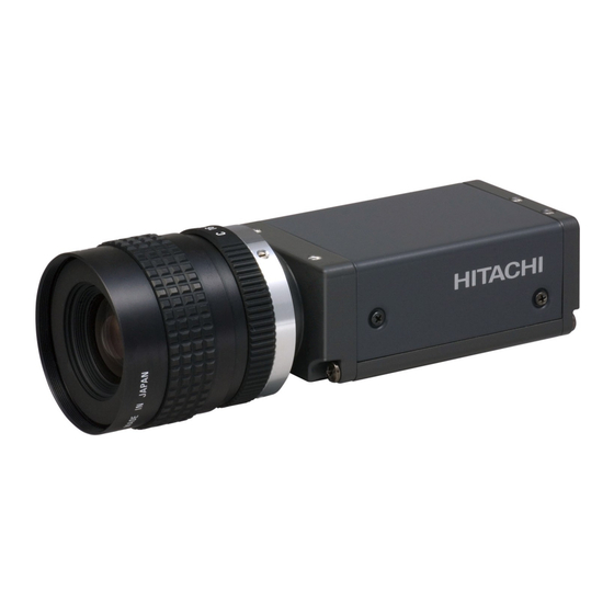
CCD camera
KP-FD500GV/F500GV
KP-FD202GV/F202GV
KP-FD145GV/F145GV
KP-FD140GV/F140GV
KP-FD83GV/F83GV
KP-FD33GV/F33GV
Operation Manual
Thank you for producing this fine Hitachi Kokusai Electric CCD camera.
Before using the camera, please read this operation manual carefully and
keep this manual on file for ready reference in the future.
Hitachi Kokusai Electric Inc.
RoHS Compliant
These products compile with the requirement of he RoHS (Restriction of the
use of Certain Hazardous Substances in Electrical and electronic Equipment)
Directive 2002/95/EC.
August 31, 2012 Version 1.11
For R1 or later models
Advertisement
Table of Contents

Related Manuals for Hitachi KP-FD500GV


Summary of Contents for Hitachi KP-FD500GV
-
Page 1: Ccd Camera
KP-FD83GV/F83GV KP-FD33GV/F33GV Operation Manual Thank you for producing this fine Hitachi Kokusai Electric CCD camera. Before using the camera, please read this operation manual carefully and keep this manual on file for ready reference in the future. Hitachi Kokusai Electric Inc. -
Page 2: Important Safety Instructions
IMPORTANT SAFETY INSTRUCTIONS 1. Read Instructions All the safety and operating instructions should be read before the product is operated. 2. Retain Instructions The safety and operating instructions should be retained for future reference. 3. Heed Warnings All warnings on the product and the operating instructions should be adhered to. 4. - Page 3 WICHTIGE SICHERHEITS ANWEISUNGEN 1. Alle Anweisungen lesen Vor Betrieb des Erzeugnisses sollten alle Sicherheits-und Bedienungsanleitungen gelesen werden. 2. Die Anweisungen aufbewahren Die Sicherheits-und Bedienungsanleitungen sollten fünftigen Bezug aufbewahrt werden. 3. Warnungen beachten Die Warnungen auf dem Erzeugnis und in den Bedienungsanleitungen solten beachtet werden. 4.
- Page 4 MISES EN GARDE IMPORTANTES 1. Lire les instructions Lire toutes les instructions de sécurité et de fonctionnement avant de faire fonctionner l’appareil. 2. Conserver ces instructions Conserver les instructions de sécurité et de fonctionnement á des fins de référence ultérieure. 3.
-
Page 5: Important Notice
WARNING Changes or modifications not expressly approved by HITACHI KOKUSAI ELECTRIC responsible for compliance could void the user’s authority to operate the equipment. - Page 6 Note: This product using following equipments satisfies the CE standards. The shield type camera cable (C-201KSS) The shield type LAN cable (C5E(S-HFR)(K)-HSL-1: Oki) Clamp filter (ZCAT 2035-0930A: TDK) at both ends (camera and video processor ends).
- Page 7 Note: This product using following equipments satisfies the CE standards. The shield type camera cable (C-201KSS) The shield type LAN cable (C5E(S-HFR)(K)-HSL-1: Oki) Clamp filter (ZCAT 2035-0930A: TDK) at both ends (camera and video processor ends).
- Page 8 Note: This product using following equipments satisfies the CE standards. The shield type camera cable (C-201KSS) The shield type LAN cable (C5E(S-HFR)(K)-HSL-1: Oki) Clamp filter (ZCAT 2035-0930A: TDK) at both ends (camera and video processor ends).
- Page 9 Note: This product using following equipments satisfies the CE standards. The shield type camera cable (C-201KSS) The shield type LAN cable (C5E(S-HFR)(K)-HSL-1: Oki) Clamp filter (ZCAT 2035-0930A: TDK) at both ends (camera and video processor ends).
- Page 10 Note: This product using following equipments satisfies the CE standards. The shield type camera cable (C-201KSS) The shield type LAN cable (C5E(S-HFR)(K)-HSL-1: Oki) Clamp filter (ZCAT 2035-0930A: TDK) at both ends (camera and video processor ends).
- Page 11 Note: This product using following equipments satisfies the CE standards. The shield type camera cable (C-201KSS) The shield type LAN cable (C5E(S-HFR)(K)-HSL-1: Oki) Clamp filter (ZCAT 2035-0930A: TDK) at both ends (camera and video processor ends).
- Page 12 ・ Sop using the camera at the approach of electrical storm (thunder audible). Protect the camera from rain if using it outdoors. ・ In event the camera shows any abnormality, switch off the camera and disconnect the power cord. Contract a Hitachi Denshi service representative.
-
Page 13: Table Of Contents
Table of Contents 1. Overview ········································································································································································································ 1 2. Standard Composition ············································································································································································· 1 3. Features ········································································································································································································· 1 4. Section name and functions ································································································································································ 2 5. Camera mounting ······················································································································································································· 2 6. Lens ················································································································································································································· 2 7. Optical filter ································································································································································································· 3 8. Connector ····································································································································································································· 4 9. -
Page 14: Overview
Features ・High resolution The 2/3-inch 5.00 million pixels (KP-FD500GV/F500GV), the 1/1.8-inch 2.02 million pixels (KP-FD202GV/F202GV), the 2/3-inch 1.45 million pixels (KP-FD145GV/F145GV), the 1/2-inch 1.45 million pixels (KP-FD140GV/F140GV), the 1/3-inch 0.8 million pixels (KP-FD83GV/F83GV) and the 1/3- inch 0.33 million pixels (KP-FD33GV/F33GV) square lattices CCD achieve a high resolution. -
Page 15: Section Name And Functions
Section name and functions Camera / Tripod adaptor mounting screw holes Ethernet connector Lens mount Use for digital video output and (C mount) camera control signal input/ output signal. DC IN/SYNC connector Use for DC+12V power or external trigger /VD signal input. Camera / Tripod adaptor mounting screw holes Camera mounting... -
Page 16: Optical Filter
Note: Prior to removing the optical filter, be sure to turn off the power. Since garbage etc. invades into image reception surface camera, please work under the clean air, such as a CLEAN ROOM. * IR cut filter is equipped in the KP-FD500GV/FD202GV/FD145GV/FD140GV/FD83GV/FD33GV. Dummy glass is equipped in the KP-F500GV/F202GV/F145GV/F140GV/F83GV/F33GV. -
Page 17: Connector
Connector 1. Ethernet connector LED 1 LED 2 PIN NO. Signal TRP1+ TRP1- TRP2+ TRP3+ TRP3- TRP2- TRP4+ TRP4- Status LED 1 LED 2 Immediately after Power ON Green Light On Orange Light On 1Gb Transmission Green Light On Orange Blink On 100Mb Transmission Red Light On Orange Blink On... -
Page 18: System Example
(1) Please connect the camera to device for Gigabit Ethernet (1000BASE-T). Please set the imaging size according to following formula when the camera is connected to 100BASE network. (Image Width) x (Image Height) x (Data bit) ≦ 20000000 ・・・ KP-FD500GV ≦ 18750000 ・・・ KP-F500GV ≦... - Page 19 (8) In the CE Marking region, use following specified cables and clamp filters Camera cable (C-201KSS) HITACHI LAN cable Camera (C5E(S-HFR)(K)-HSL-1: Oki) Clamp filter (ZCAT 2035-0930A: TDK) Ferrite core Plastic case Camera cable / LAN cable Approx. 100 to 150 mm...
-
Page 20: Functions And Operations
Functions and operations Various mode setup and adjustment of KP-FD500GV/F500GV/FD202GV/F202GV/FD145GV/F145GV/FD140GV/F140GV /FD83GV/F83GV/FD33GV/F33GV are performed by the remote control via Gigabit Ethernet. Operation and adjustment way of function utilized are described below. Each command is classified into following 5 types: ・ Enumeration : Command dealing with enumeration-type parameter ・... - Page 21 245: KP-FD145GV/FD140GV 261: KP-F145GV/F140GV 297: KP-FD83GV 313: KP-F83GV 384: KP-FD33GV 403: KP-F33GV : 1 to 36 : KP-FD500GV 7 to 63: KP-F500GV 7 to 251: KP-FD202GV 7 to 265: KP-F202GV 7 to 245: KP-FD145GV/FD140GV 7 to 261: KP-F145GV/F140GV 7 to 297: KP-FD83GV...
- Page 22 492: KP-FD33GV/F33GV (3) WIDTH : Set the actual image width Command name : Width (Integer / Standard) Address : A0020000 h Values (Factory setting 2448: KP-FD500GV/F500GV 1620: KP-FD202GV/F202GV 1280: KP-FD145GV/FD140GV 1360: KP-F145GV/F140GV 1024: KP-FD83GV/F83GV 652: KP-FD33GV/F33GV) : 2 to WIDTH MAX Set the actual image width at intervals of 2 pixels.
- Page 23 When set to 1, not perform the binning mode. When set to 2, the vertical image size will be half and frame rate will nearly double. *KP-FD500GV/FD202GV/FD145GV/FD140GV/FD83GV/FD33GV have only 1 (7) PIXEL FORMAT : Setting of the pixel format ・PIXEL FORMAT : Set the pixel format Command name :...
- Page 24 (8) PIXEL COLOR FILTER : Kind of color filter equipped the camera Command name : PixelColorFilter (Enumeration / Standard) Address : A0020018 h Values (read only) : 0 "BayerRG" The camera has RG Bayer color filter. 4 "None" The camera has no color filter. (9) PARTIAL SCAN :...
- Page 25 : GainRaw (Integer / Standard) Address : A0070004 h Values (Factory setting 0) : 0 to 336 : KP-FD500GV/F500G Adjust the gain level 0 to 12dB in 337 steps at intervals of 0.0358dB. 0 to 503 : Models except the above Adjust the gain level 0 to 18dB in 504 steps at intervals of 0.0358dB.
- Page 26 : GainAutoLowerLimitRaw (Integer / Standard) Address : A0F70020 h Values (Factory setting 0) : 0 to 336 : KP-FD500GV/F500G Adjust the gain level 0 to 12dB in 337 steps at intervals of 0.0358dB. 0 to 503 : Models except the above Adjust the gain level 0 to 18dB in 504 steps at intervals of 0.0358dB.
- Page 27 ・VARIABLE1 : Setting of the Variable shutter 1 Command name : ExposureTimeAbs (Float / Standard) Address : A0030044 h Values (Factory setting 111111: KP-FD500GV 62500: KP-F500GV 33333: KP- FD202GV/F202GVFD145GV/F145GV/FD140GV/F140GV 27777: KP-FD83GV/F83GV 11111: KP-FD33GV/F33GV) : 10 to 10000000 Set the shutter speed in the range from 1/100000 to 10 second in us.
- Page 28 ・LOWER LIMIT1 : Lower limit 1 of automatic adjustment range Command name : ExposureAutoLowerLimitAbs (Float / Custom) Address : A0F30020 h Values (Factory setting 10) : 10 to 111111: KP-FD500GV 62500: KP-F500GV 33333: KP- FD202GV/F202GVFD145GV/F145GV/FD140GV/F140GV 27777: KP-FD83GV/F83GV 11111: KP-FD33GV/F33GV) :...
- Page 29 (12) MASKING : Setting of 6 vector independent masking (primary color R G B and complementary color Ye Cy Mg saturation and hue can be separately varied). *for only KP-FD500GV/FD202GV/FD145GV/FD140GV/FD83GV/FD33GV *unusable when RAW data output mode ・MODE : Select the mode Command name :...
- Page 30 Come near to Green Come near to Red (13) PAINT BLACK : Setting of paint black (color level of Red, Green and Blue can be separately varied) *for only KP-FD500GV/FD202GV/FD145GV/FD140GV/FD83GV/FD33GV *unusable when RAW data output mode ・MODE : Select the mode Command name :...
- Page 31 ・LEVEL : Setting for the threshold level Command name : WhiteSpotCorrectLevelRaw (Integer /Custom) Address : A0FF00A4 h Values (Factory setting 20: KP-FD500GV/F500GV 80: KP-FD202GV/FD145GV/FD140GV/FD83GV/FD33GV 100: KP-F202GV/F145GV/F140GV/F83GV/F33GV) : 0 to 255 Set the threshold level of white spot detection in 8-bit gradation.
- Page 32 : 1 When 1 is written, the pixel specified by POSITON X/Y is deleted from list. (18) BALANCE ADJUST : Setting for balance of Left and Right screen *for only KP-FD500GV/F500GV ・MODE : Select the mode Command name : BalanceAdjustMode (Enumeration / Custom)...
- Page 33 Values (Factory setting 0) : 0 to 4096 Set the following range at intervals. Camera Selector of Trigger Setting range Intervals FrameStart 3.73 µs to 19.57 ms KP-FD500GV Approx. 4.78 µs FrameTransferStart 108.7 µs to 19.68 ms FrameStart 4.42 µs to 11.2 ms KP-F500GV Approx. 2.7 µs FrameTransferStart 65.2 µs to 11.26 ms...
- Page 34 Timer is stopped at the same time as the end of exposure. 1 to 4096 Set the following range and intervals. Camera Setting range Intervals KP-FD500GV from 4.78 µs to 19.57 ms Approx. 4.78 µs KP-F500GV from 2.7 µs to 11.2 ms Approx. 2.7 µs KP-FD202GV/F202GV from 1.6 µs to 6.55 ms...
- Page 35 KP-FD500GV from 0.32 µs to 19.57 ms Approx. 4.78 us KP-F500GV from 0.19 µs to 11.2 ms Approx. 2.7 us KP-FD202GV/F202GV from 0.08 µs to 6.55 ms Approx. 1.6 us KP-FD145GV/F145GV from 0.14 µs to 8.35 ms Approx. 2.04 us KP-FD140GV/F140GV from 0.14 µs to 8.35 ms...
- Page 36 5. Commands about SAVE/LOAD This product can save settings of 1. 2. 3. 4. to four memories. (1) USER SETS : Setting of SAVE/LOAD ・SELECTOR : Select the SAVE/LOAD channel Command name : UserSetSelector (Enumeration / Standard) Address : A00A0000 h Values (Factory setting 0) :...
- Page 37 Values (read only) : "Hitachi_Kokusai_Electric_Inc" (2) MODEL NAME : Camera name Command name : DeviceModelName (String / Standard) Address : 00000068 h Values (read only) : "KP-FD500GV": KP-FD500GV "KP-F500GV": KP-F500GV "KP-FD202GV": KP-FD202GV "KP-F202GV": KP-F202GV "KP-FD145GV": KP-FD145GV "KP-F145GV": KP-F145GV "KP-FD140GV": KP-FD140GV "KP-F140GV": KP-F140GV "KP-FD83GV": KP-FD83GV...
- Page 38 (9) MONO OR COLOR : Whether the camera is B/W camera or Color camera Command name : IsMonoCamera_IncFao (Integer / Custom) Address : A0FFFF00 h Values (read only) : 1: KP-F500GV/F202GV/F140GV/F140GV/F83GV/F33GV It means black and white camera 2: KP-FD500GV/FD202GV/FD145GV/FD140GV/FD83GV/FD33GV It means color camera...
- Page 39 7. Commands about GigE Vision transport layer (1) PAYLOAD SIZE : payload size Command name : DeviceVendorName (String / Standard) Address : A009F000 h Values (read only) : "Hitachi_Kokusai_Electric_Inc" (2) MAC ADDRESS : MAC address of the camera Command name :...
- Page 40 ・DEFAULT GATEWAY : Setting of persistent default gateway Command name : GevCurrentDefaultGateway (Integer / Standard) Address : 0000066C h Values (Factory setting 0) : 0 to FFFFFFFF h Set persistent default gateway. (6) HEARTBEAT TIMEOUT : Setting of heartbeat timeout Command name :...
-
Page 41: Frame Rate
Frame rate Maximum frame rate of KP-FD500GV/FD202GV/FD140GV/FD83GV/FD33GV/F33GV are decided by data volume per pixel and number of pixel per frame. Data volume per pixel is as follows by set pixel format. Data / pixel Pixel format 8bit RAW 8bit / MONO 8bit... - Page 42 (4) KP-FD145GV/F145GV/FD140GV/F140GV 8-16 bit/pixel 24 bit/pixel 32 bit/pixel 48 bit/pixel 200000 400000 600000 800000 1000000 1200000 1400000 Pixels/frame (5) KP-FD83GV/F83GV 8-24 bit/pixel 32 bit/pixel 48 bit/pixel 100000 200000 300000 400000 500000 600000 700000 800000 pixels/frame (6) KP-FD33GV/F33GV 8-24 bit/pixel 32 bit/pixel 48 bit/pixel 40000 80000...
- Page 43 When "PartialScanMode" is "On", number of total line and frame rate can be calculated from following equation using height of grabbing picture. (1) KP-FD500GV Total line = 22 + Height + (2061 - Height) / 4 ・・・ omit the figures after the decimal fractions...
- Page 44 (4) KP-FD140GV/F140GV Total line = 22 + Height + (1048 - Height) / 10 ・・・ omit the figures after the decimal fractions Frame rate = (57769000 / 1790) / Total line 1000 Height of picture grabbing [H] (5) KP-FD83GV/F83GV Total line = 19 + Height + (775 - Height) / 10 ・・・ omit the figures after the decimal fractions Frame rate = (37000000 / 1270) / Total line Height of picture grabbing [H] (6) KP-FD33GV/F33GV...
- Page 45 For example: when AcquisitionFrameRateRaw is 15 and frame rate by partial scan is 50, the camera drives at 15 fps. 3. Partial scan mode When PartialScanMode is Off, the camera drives at the frame rate that is same as when Height is HeightMax. ・Frame rate of each model when Height is HeightMax KP-FD500GV KP-F500GV KP-FD202GV/F202GV KP-FD145GV/F145GV...
-
Page 46: Packet Size And Packet Delay
If packet size is set more than MTU (Maximum Transmission Unit), the camera cannot transfer image data. 2. Packet delay KP-FD500GV/F500GV/FD202GV/F202GV/FD145GV/F145GV/FD140GV/F140GV/FD83GV/F83GV/FD33GV/F33GV can be set delay time inter image data packets. Image data transfer rate (or frame rate) decrease when packet delay is increased. This would prevent image data conflict when multiple camera connection. -
Page 47: Trigger Mode
Trigger mode Trigger mode setting of KP-FD500GV/F500GV/FD202GV/F202GV/FD145GV/F145GV/FD140GV/F140GV/FD83GV/F83GV /FD33GV/F33GV are following procedure. 1. Fixed shutter mode When external trigger signal is POSITIVE (TriggerActivation: "RisingEdge"), after the trigger signal rise, exposure is start The exposure time is set by the camera electronic shutter speed. - Page 48 3. Reset control mode The readout timing can be set arbitrary set by input the trigger signal (readout pulse) different from the exposure beginning when Fixed shutter mode or ONE trigger mode. Execute following procedure in addition Fixed shutter/ONE trigger settings. (1) TriggerSelector →...
- Page 49 5. Others Following table describe camera behavior according to combination of value of ExposureMode and TriggerMode. Command Actual behavior ExposureMode TriggerMode Normal mode (Normal shutter) Fixed shutter mode Normal mode (Normal shutter) Fixed shutter mode & Reset control Normal mode (Normal shutter) Fixed shutter mode Normal mode (Normal shutter) Fixed shutter mode &...
-
Page 50: Digital Output
Digital output The method of setting of digital output is explained. 1. Flash out (strobe pulse) This camera can output flash pulse when trigger mode or electric shutter mode, (A) When output flash pulse at the same time as exposure time and without delay. (1) LineSelector →... -
Page 51: Trigger Operation And Timing Chart
Strobe width1 (*2) Strobe width2 (*3) Data output VD output (Low active) 9H (*4) 1/Self frame rate [second] (*1) KP-FD500GV 0.32µs to 19.57ms Approx. 4.78µs/step KP-F500GV 0.19µs to 11.20ms Approx. 2.7µs/step KP-FD202GV/F202GV 0.08µs to 6.55ms Approx. 1.6µs/step KP-FD145GV/F145GV 0.14µs to 8.35ms Approx. - Page 52 Data output VD output (Low active) (*1) All model T1 = 1 / Self frame rate [second] (*2) KP-FD500GV Photocoupler delay + 0.0 to 19.57ms Approx. 4.78µs/step KP-F500GV Photocoupler delay + 0.0 to 11.20ms Approx. 2.7µs/step KP-FD202GV/F202GV Photocoupler delay + 0.0 to 6.55ms Approx.
- Page 53 Data Output VD output (Low active) (*1) All model 1 / Self frame rate [second] (*2) KP-FD500GV Photocoupler delay + 0.0 to 19.57ms Approx. 4.78µs/step KP-F500GV Photocoupler delay + 0.0 to 11.20ms Approx. 2.7µs/step KP-FD202GV/F202GV Photocoupler delay + 0.0 to 6.55ms Approx.
- Page 54 Readout delay (*6) VD output (Low active) (*1) All model 1 / Self frame rate [second] (*2) KP-FD500GV Photocoupler delay + 0.0 to 19.57ms Approx. 4.78µs/step KP-F500GV Photocoupler delay + 0.0 to 11.20ms Approx. 2.7µs/step KP-FD202GV/F202GV Photocoupler delay + 0.0 to 6.55ms Approx.
- Page 55 Readout delay (*7) VD output (Low active) (*1) All model T1 = 1 / Self frame rate [second] (*2) KP-FD500GV Photocoupler delay + 0.0 to 19.57ms Approx. 4.78µs/step KP-F500GV Photocoupler delay + 0.0 to 11.20ms Approx. 2.7µs/step KP-FD202GV/F202GV Photocoupler delay + 0.0 to 6.55ms Approx.
- Page 56 When external VD pulse is inputted, internal VD is reset. Exposure time is established shutter speed. more than 1/self frame rate [sec] VD input (Falling Edge) more than 10us Data output VD output (Low active) KP-FD500GV : 4.21µs KP-F500GV : 4.19µs KP-FD202GV/F202GV : 4.39µs KP-FD145GV/F145GV : 3.70µs KP-FD140GV/F140GV : 3.88µs KP-FD83GV/F83GV :...
-
Page 57: Input /Output Signal
Input / Output signal 1. Input signal The level of the trigger signal input to KP-FD500GV/F500GV/FD202GV /F202GV/FD145GV/F145GV/FD140GV/F140GV /FD83GV/F83GV/FD33GV /F33GV is as follows. High level : +5.0 to +24V Low level 0 to +0.3V Threshold (Low --> High) : 3.7V ± 0.5V Threshold (High -->... -
Page 58: Output Sequence Of Raw Data
Output sequence of RAW data ・KP-FD500GV ・・・ Pixel 2447 2448 ・ ・ ・ 2049 2050 Line ・KP-FD202GV ・・・ Pixel 1619 1620 ・ ・ ・ 1219 1220 Line... - Page 59 ・KP-FD145GV/140GV ・・・ Pixel 1359 1360 ・ ・ ・ 1023 1024 Line ・KP-FD83GV ・・・ Pixel 1023 1024 ・ ・ ・ Line ・KP-FD33GV ・・・ Pixel 651 652 ・ ・ ・ Line...
-
Page 60: Spectral Response
Spectral response ・KP-FD500GV IR cut filter Wave Length (nm) ・KP-F500GV IR cut filter 1000 Wave Length (nm) - Page 61 ・KP-FD202GV IR cut filter Wave Length (nm) ・KP-F202GV IR cut filter 1000 Wave length [nm]...
- Page 62 ・KP-FD145GV IR cut filter Wave Length (nm) ・KP-F145GV IR cut filter 1000 Wave Length (nm)
- Page 63 ・KP-FD140GV IR cut filter Wave Length (nm) ・KP-F140GV IR cut filter 1000 Wave Length (nm)
- Page 64 ・KP-FD83GV IR cut filter Wave Length (nm) ・KP-F83GV IR cut filter 1000 Wave Length (nm)
- Page 65 ・KP-FD33GV IR cut filter Wave Length (nm) ・KP-F33GV IR cut filter 1000 Wavelength [nm]...
-
Page 66: Specifications
Specifications Specifications of KP-FD500GV/FD202GV are showing. KP-FD500GV KP-FD202GV KP-FD145GV Imaging device 2/3-inch interline CCD 1/1.8-inch interline CCD 2/3-inch interline CCD Total pixels 2536 (H) x 2068 (V) 1688 (H) x 1248 (V) 1432 (H) x 1050 (V) Effective pixels 2456 (H) x 2058 (V) - Page 67 Specifications of KP-FD140GV/FD83GV/FD33GV are showing. KP-FD140GV KP-FD83GV KP-FD33GV Imaging device 1/2-inch interline CCD 1/3-inch interline CCD 1/3-inch interline CCD Total pixels 1434 (H) x 1050 (V) 1077 (H) x 788 (V) 692 (H) x 504 (V) Effective pixels 1392 (H) x 1040 (V) 1034 (H) x 779 (V) 656 (H) x 494 (V) Pixel pitch...
- Page 68 Specifications of KP-F500GV/F202GV/F145GV are showing. KP-F500GV KP-F202GV KP-F145GV Imaging device 2/3-inch interline CCD 1/1.8-inch interline CCD 2/3-inch interline CCD Total pixels 2536 (H) x 2068 (V) 1688 (H) x 1248 (V) 1434 (H) x 1050 (V) Effective pixels 2456 (H) x 2058 (V) 1628 (H) x 1236 (V) 1392 (H) x 1040 (V) Pixel pitch...
- Page 69 Specifications of KP-F140GV/F83GV/F33GV are showing. KP-F140GV KP-F83GV KP-F33GV Imaging device 1/2-inch interline CCD 1/3-inch interline CCD 1/3-inch interline CCD Total pixels 1434 (H) x 1050 (V) 1077 (H) x 788 (V) 692 (H) x 504 (V) Effective pixels 1392 (H) x 1040 (V) 1034 (H) x 779 (V) 656 (H) x 494 (V) Pixel pitch...
-
Page 70: Dimensions
Dimensions 13 14.5... - Page 71 UDX Akihabara Bldg. 14-1 Sotokanda 4-choume, Chiyoda-ku, Tokyo 101-8980, Japan Phone: +81(0) 3-6734-9432, Fax: +81(0) 3-5209-5942 URL: http://www.hitachi-kokusai.co.jp/global/ Hitachi Kokusai Electric (Shanghai) Co., Ltd. Beijing Branch : Room 1415, Beijing Fortune Building, 5 Dong San Huan Bei-Lu, Chao Yang District, Beijing, 100004 China Phone: +86(0) 10-6590-8755/8756, Fax: +86(0) 10-6590-8757 Hitachi Kokusai Electric America, Ltd.
Need help?
Do you have a question about the KP-FD500GV and is the answer not in the manual?
Questions and answers