Table of Contents
Advertisement
Quick Links
Advertisement
Table of Contents

Summary of Contents for Hitachi KP-FD30
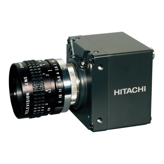
- Page 1 CCD Color Camera KP-FD30 Operation manual Thank you for procuring this fine Hitachi Kokusai Electric color CCD camera. Before using the camera, please read this operation manual carefully and keep this manual on file for ready reference in the future.
-
Page 3: Operating Considerations
Operating considerations Power supply ・Do not aim the camera lens at the sun. Be sure to use the power source specified in the Major ・Do not shoot strong light or a scene including strong light. Specifications. When such a scene is shot, vertical trailings will appear. ・Before plugging or unplugging a connector, be sure However, this is not due to failure. -
Page 4: Section Names And Functions
General Composition The KP-FD30 is a single CCD type RGB color camera which ●Camera(with C mount adaptor) utilized the progressive scan CCD image sensor with square ●Operation manual pixel for VGA format of 1 / 2-inch which adopted the RGB primary color mosaic filter. -
Page 5: External View
External View Unit:mm Connections EXP. VGA (progressive scan) mode... - Page 6 Connectors ● Multi connector(inch size screw) ● DC input connector[DC IN] Pin No. Signal name Pin No. Signal name R /(C)output G/Y output +12V input B /(VBS)output WE output GND (TXD/RXD) Plug:R03-P3F VIDEO GND VIDEO GND VIDEO GND UNREG +12V input ●...
-
Page 7: Main Specifications
Main specifications 1. Imaging device 1/2-inch progressive scan interline CCD 6.Video signal output Total number of 692(H) x 504(V) pixels RGB output 0.7 Vp-p/75-ohm Positive No. of effective 659(H) x 494(V) SYNC (G on SYNC) 0.3 Vp-p Negative pixels MULTI connector (D-sub15) (*1) Unit cell size 9.9(H) x 9.9(V)μm ( Square pixel ) -
Page 8: Remote Connection
Remote Connection This camera can perform remote control of various setup of Note A camera with a personal computer. Please perform extraction and insertion of a remote Please perform wiring as shown in a figure to an optional plug after turning off a camera power supply. remote plug, and connect with the remote connector on the back of a camera after checking wiring correctly. -
Page 9: Setting Menu Description
Setting menu description The camera setting and adjustments can be changed to conform to conditions of use. Use the setting menu indicated on the monitor screen to check and change the settings and adjustments. The setting menu is comprised as follows. Display on/off positioning setting Main setting menu Camera title setting menu... -
Page 10: Detection Area Setting
CAMERA NO.1 ●● CAMERA TITLE MENU ●● Display on/off and position MODE :OFF [OFF, TOP, BOTTOM] Return (Return to the main menu) RET End (Return to the normal screen) END Camera title position setting MODE: OFF ●● CAMERA TITLE MENU ●● (3)Auto level control[ALC MENU]... -
Page 11: The Camera
4)AGC setting[AGC MENU] 5)Shutter speed setting[SHUTTER MENU] AGC (automatic gain control) mode is set up. Electronic shutter mode is set up. Please set up according to the operating environment of Please set up according to the operating environment of the the camera. -
Page 12: Camera Reset
6) White balance setting menu [WHITE BALANCE MENU] ●White balance detection area setting White balance mode is set up.Please set up according to the Shift the cursor to Area Select and press the Set button to operating environment of the camera. display the White balance detection area select menu. -
Page 13: Internal Switch Setting
Internal switch setting To access the internal switches, remove the four screws on Screws Screws the back panel of the camera. Carefully remove the pack panel. There are two internal switches that may need to be changed depending on the use and connection of the camera. (1)SW6001 HD/SYNC, VD input-and-output change. - Page 17 (Important) About an external trigger signal prohibition period When falling (rising) of a trigger pulse enters during the prohibition of the following figure, color reappearance may not be carried out correctly. Please input the trigger pulse of the following specification not to input a trigger pulse during the prohibition. VD out SYNC VSYN...


Need help?
Do you have a question about the KP-FD30 and is the answer not in the manual?
Questions and answers