Table of Contents
Advertisement
Quick Links
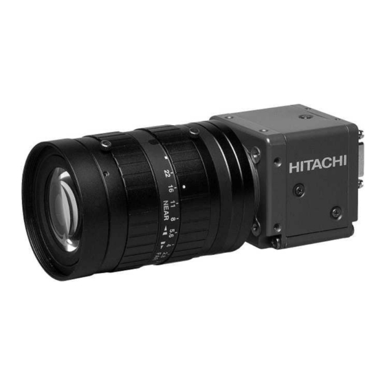
High pixel CCD camera
KP-F500PCL/SCL
KP-FR500 PCL/SCL
Operation Manual
Thank you for purchase this fine Hitachi Kokusai Electric CCD camera.
Before using the camera, please read this operation manual carefully.
Hitachi Kokusai Electric Inc.
RoHS Compliant
These products comply with the requirement of the RoHS (Restriction of the
use of Certain Hazardous Substances in Electrical and electronic Equipment)
Directive 2002/95/EC.
The 10th edition in August, 2012.
For R1 or later models
Advertisement
Table of Contents

Related Manuals for Hitachi KP-F500PCL/SCL


Summary of Contents for Hitachi KP-F500PCL/SCL
- Page 1 High pixel CCD camera KP-F500PCL/SCL KP-FR500 PCL/SCL Operation Manual Thank you for purchase this fine Hitachi Kokusai Electric CCD camera. Before using the camera, please read this operation manual carefully. Hitachi Kokusai Electric Inc. RoHS Compliant These products comply with the requirement of the RoHS (Restriction of the use of Certain Hazardous Substances in Electrical and electronic Equipment) Directive 2002/95/EC.
-
Page 2: Important Safety Instructions
IMPORTANT SAFETY INSTRUCTIONS 1. Read Instructions All the safety and operating instructions should be read before the product is operated. 2. Retain Instructions The safety and operating instructions should be retained for future reference. 3. Heed Warnings All warnings on the product and the operating instructions should be adhered to. 4. - Page 3 WICHTIGE SICHERHEITSANWEISUNGEN 1. Alle Anweisungen lesen Vor Betrieb des Erzeugnisses sollten alle Sicherheits-und Bedienungsanleitungen gelesen werden. 2. Die Anweisungen aufbewahren Die Sicherheits-und Bedienungsanleitungen sollten fünftigen Bezug aufbewahrt werden. 3. Warnungen beachten Die Warnungen auf dem Erzeugnis und in den Bedienungsanleitungen solten beachtet werden. 4.
- Page 4 MISES EN GARDE IMPORTANTES 1. Lire les instructions Lire toutes les instructions de sécurité et de fonctionnement avant de faire fonctionner l’appareil. 2. Conserver ces instructions Conserver les instructions de sécurité et de fonctionnement á des fins de référence ultérieure. 3.
-
Page 5: Important Notice
Operation of this product in a residential area is likely to cause harmful interference in which case the user will be required to correct the interference at his own expense. WARNING Changes or modifications not expressly approved by Hitachi Denshi responsible for compliance could void the user’s authority to operate the equipment. For Canada This product does not exceed the class A/class B limits for radio noise emissions from digital apparatus as set out in the radio interference regulations. - Page 7 ・ Stop using the camera at the approach of electrical storm (thunder audible). Protect the camera from rain if using it outdoors. ・ In event the camera shows any abnormality, switch off the camera and disconnect the power cord. Contract a Hitachi Denshi service representative.
-
Page 8: Table Of Contents
Table of Contents 1. Overview ··········································································································································································································· 1 2. Standard Composition ················································································································································································ 1 3. Features ············································································································································································································ 1 4. System example ···························································································································································································· 1 5. Section name and functions ···································································································································································· 2 6. Camera mounting ·························································································································································································· 2 7. Lens ····················································································································································································································· 2 8. Optical filter ····································································································································································································· 3 9. -
Page 9: Overview
Overview KP-F500PCL/SCL are CameraLink output type black and white camera which utilized the 2/3 –inch progressive scan CCD image sensor with square pixel. KP-FR500PCL/SCL are RAW data output type. It provide images of unparalleled quality at 16 frame per second non-interlaced output. -
Page 10: Section Name And Functions
Section name and functions Camera / Tripod adaptor mounting screw holes CameraLink connectors Lens mount Use for digital video output (C mount) and camera control signal input/output signal. DC IN/SYNC 12pin connector Use for DC+12V power (KP-F500SCL, KP-FR500SCL) and external trigger/VD signal input. -
Page 11: Optical Filter
Optical filter How to remove the IR cut filter. (1) Remove two screws ① and filter holder ② will come off. (2) Remove the IR cut filter ③ from filter frame ④. (3) Then, reinstall and secure filter holder ② with two screws ①. Note: Prior to removing the optical filter, be sure to turn off the power. -
Page 12: Connector
Connector 1. CameraLink connector D.OUT1 (Connector 1) Pin No. Signal Pin No. Signal +12V (KP-F500PCL/FR500PCL) GND (KP-F500SCL/FR500SCL) TXOUT 0 (-) TXOUT 0 (+) TXOUT 1 (-) TXOUT 1 (+) TXOUT 2 (-) TXOUT 2 (+) TXCLKOUT (-) TXCLKOUT (+) TXOUT 3 (-) TXOUT 3 (+) RX (+) [ SERTC (+) ] RX (-) [ SERTC (-) ]... -
Page 13: Functions And Operations
Functions and operations Various mode setup and adjustment of KP-F500PCL/SCL and KP-FR500PCL/SCL are performed by the remote control via CameraLink. Operation and adjustment way of function utilized are described below. See "Remote control" and "Command list" (page 8 to 17) about communication method of each command. - Page 14 : Output LVAL2 and horizontal pixel is set to 1224 (multiple of 8) clocks. (8) GAIN : Setting of electrical sensitivity 0 (Factory setting) to 18dB : Set from 0 to 18dB in 504 steps (for KP-F500PCL/SCL). 0 (Factory setting) to 12dB : Set from 0 to 12dB in 336 steps (for KP-FR500PCL/SCL).
- Page 15 (12) BALANCE ADJUST : Setting for the balance of the right and left screen. -MODE- : Select mode : No adjustment for the balance. MANUAL : Adjustment by the manual operation. AUTO (Factory setting) : Auto adjustment for the balance. -RIGHT GAIN- : Setting for the gain value of the right screen -1.1456dB~+1.1456dB : When MANUAL, set this value for the right screen by 64 steps.(Factory setting: 0dB)
-
Page 16: Remote Control
Remote control 1. Comms* specifications ・Control system : Start-stop synchronization system ・Transmission rate : 9600 bps ・Data length : 8 bit ・Star bit : 1 bit ・Stop bit : 1 bit ・Parity : None ・Bit transfer : LSB first *Comms: Communications 2. - Page 17 ACK code (06H) HITACHI Transmit data (ASCII code) ACK code (06H) Slave (KP-F500PCL/SCL Master (Machine) KP-FR500PCL/SCL) ① Session starts when ENQ is sent from master to slave. ② Slave acknowledges by returning ACK to master. ③ Master sends data to slave.
- Page 18 ENQ code (05H) HITACHI NACK code (15H) ENQ code (05H) NACK code (15H) Slave (KP-F500PCL/SCL ENQ code (05H) KP-FR500PCL/SCL) Master (Machine) NACK code (15H) ① Master sends ENQ code to slave. ② Since ACK code cannot be sent, slave sent NACK code to master.
- Page 19 ACK code (06H) Send data (ASCII code) HITACHI 3 second elapse Send data (ASCII code) Slave 3 second (KP-F500PCL/SCL elapse Send data (ASCII code) KP-FR500PCL/SCL) Master (Machine) 3 second elapse Send data (ASCII code) ① Session starts when ENQ is sent from master to slave.
- Page 20 (6) Transmission frame error (Master receive) ENQ code (05H) ACK code (06H) Read command (ASCII code) HITACHI ACK code (06H) Read data (ASCII code) Slave 3 second (KP-F500PCL/SCL elapse KP-FR500PCL/SCL) Read data (ASCII code) Master (Machine 3 second elapse Read data (ASCII code) 3 second...
- Page 21 2 byte (ASCII code) Used for EEPROM write (0: write absent, 1: write present). ・ID No. : Camera peculiar ID. KP-F500PCL/SCL and KP-FR500PCL/SCL have (FFH). 2 byte (ASCII code) ・Area address : Classification of Send data (01H) and Read command (81H).
- Page 22 (2) Read (receive) data (slave to master) (a) Command data are converted into ASCII code and transmitted. (b) Comms byte quantity is 10. (c) Comms data format (transmission sequence) S T X Text data E T X S U M 1 byte 6 byte 1 byte...
-
Page 23: Command List
(*5) BLACK LEVEL: selectable in the range from 00 to 3F (*6) VERTICAL 2 PIXEL ADDITION is only for KP-F500PCL/SCL. (*7) PARTIAL SCAN START/WIDTH can be set only when PARTIAL SCAN MODE is ON. (*8) PARTIAL SCAN START/WIDTH: selectable in the range from 0001... - Page 24 Item ETX SUM AREA RELATIVE STATUS ID NO. DATA ADDRESS MODE MANUAL AUTO MIN(-1.1456dB) BALANCE RIGHT GAIN ADJUST (*9) MAX(+1.1456dB) MIN(-128/2048) RIGHT BLACK 0/2048 (*9) MAX(+127/2048) MODE WHITE SPOT MIN(0) CORRECTION THRESHOLD MAX(255) DETECT START FACTORY SETTING (*9) RIGHT GAIN and RIGHT BLACK are effective only when BALANCE ADJUST MODE is MANUAL.
- Page 25 (2BYTE) ・ ・ POSITION64 X POSITION64 Y (*1) VERTICAL 2 PIXEL ADDITION is only for KP-F500PCL/SCL. (*2) Reading data (1Byte) is 00 when the end is detected, 01 is the running time of detection, 02 is number of overflow. (*3) If white spot is not registered in the position, the reading data (2Bytes) is FFFF...
-
Page 26: Cameralink Output Timing Chart
CameraLink output timing chart 1. Horizontal timing 1924 clk 100 clk 318 clk 278 clk 1228 clk VIDEO Active Picture LVAL 4 clk LVAL2 1224 clk 1 clk = 15.625 ns 2. Vertical timing 2079 H 10 H 2058 H VIDEO Active Picture FVAL... - Page 27 3. Transmitter LVDS output pulse position measurement (1) Base configuration (a) 8bit D.OUT1 15.625ns (64.0000MHz) CLKX Previous Cycle Next Cycle DA7-1 DA6-1 N.U. N.U. N.U. N.U. N.U. N.U. FVAL LVAL N.U. N.U. N.U. N.U. (VD) (HD) DB2-1 DB1-1 N.U. N.U. DA1-1 DA0-1 N.U.: Not used...
- Page 28 (c) 12bit D.OUT1 15.625ns (64M.0000Hz) CLKX Previous Cycle Next Cycle DA7-1 DA6-1 N.U. DB11 DB10 DB3-1 DB2-1 N.U. FVAL LVAL (VD) (HD) DA10-1 DA9-1 DA11 DA10 DA1-1 DA0-1 N.U.: Not used When using at Base configuration, please be sure to connect CameraLink cable to D.OUT1. If the cable is connected to D.OUT2, machine may break down.
- Page 29 (2) Medium configuration (a) 8bit D.OUT1 31.25ns (32.0000MHz) CLKX Previous Cycle Next Cycle DA7-1 DA6-1 N.U. DC3-1 DC2-1 N.U. FVAL LVAL (VD) (HD) DB2-1 DB1-1 DA1-1 DA0-1 N.U.: Not used D.OUT2 31.25ns (32.0000MHz) CLKY Previous Cycle Next Cycle DD7-1 DD6-1 N.U.
- Page 30 (b) 10bit D.OUT1 31.25ns (32.0000MHz) CLKX Previous Cycle Next Cycle DA7-1 DA6-1 N.U. N.U. N.U. DB3-1 DB2-1 N.U. FVAL LVAL (VD) (HD) DA9-1 N.U. N.U. DA1-1 DA0-1 N.U.: Not used D.OUT2 31.25ns (32.0000MHz) CLKY Previous Cycle Next Cycle DD7-1 DD6-1 N.U.
- Page 31 (c) 12bit D.OUT1 31.25ns (32.0000MHz) CLKX Previous Cycle Next Cycle DA7-1 DA6-1 N.U. DB11 DB10 DB3-1 DB2-1 N.U. FVAL LVAL (VD) (HD) DA10-1 DA9-1 DA11 DA10 DA1-1 DA0-1 N.U.: Not used D.OUT2 31.25ns (32.0000MHz) CLKY Previous Cycle Next Cycle DD7-1 DD6-1 N.U.
- Page 32 4. Output sequence (1) KP-F500PCL/SCL It shows KP-F500PCL/SCL output sequence of image data. X = H/2 H = 2456 V = 2058 (a) Base configuration : Data of screen left half. This means that left to the x-th pixel on y-th line.
- Page 33 (2) KP-FR500PCL/SCL It shows KP-FR500PCL/SCL output sequence of RAW data. X = H/2 H = 2456 V = 2058 (a) Base configuration R(DA) G(DA) B(DA) : Data of screen left half. These mean R component, G component and B component. R(DB) G(DB) B(DB) : Data of screen right half.
-
Page 34: Trigger Operation And Timing Chart
*4: (Width)H Note1: Please use the partial scan in following condition. Start + Width ≦ 2059 Graph following shows frame rate in each of picture grabbing in the partial scan mode. KP-F500PCL/SCL and KP-FR500PCL/SCL Partial scan 1000 1500 2000 Width of picture grabbing [H] Note: Frame rate can be calculated from following equations using width of picture grabbing. - Page 35 2. Fixed shutter mode When external trigger signal is , after the trigger signal rise, exposure is start. The exposure time is set by the POSITIVE camera electronic shutter speed. The video output is obtained immediately after the end of fixed exposure. The strobe signal start/end can be set to shutter time.
-
Page 36: Input / Output Signal
Note1: Please use the partial scan in following condition. Start + Width ≦ 2059 Input / Output signal 1. Input signal The level of the trigger signal input to KP-F500PCL/SCL and KP-FR500PCL/SCL is as follows. (1) Input from CameraLink cable LVDS level. (2) Input from 12-pin connector High level : +2.5 to +5.0 V... -
Page 37: Spectral Response
Spectral response Spectral response of KP-F500PCL/SCL and KP-FR500PCL/SCL are showing. 1. KP-F500PCL/SCL IR cut filter 1000 Wave Length (nm) 2. KP-FR500PCL/SCL IR cut filter Wave Length (nm) -
Page 38: Specifications
Control system Start-stop synchronization system Control items TRIGGER, OUTPUT SIGNAL, SHUTTER SPEED, CONFIGURATION, DATA BIT, VD/FVAL, HD/LVAL/LVAL2, GAIN, BLACK LEVEL, VERTICAL 2 PIXEL ADDITION (only KP-F500PCL/SCL), PARTIAL SCAN WHITE SPOT CORRECTION、BALANCE ADJUST、FACTORY SETTING 25) Power supply DC12V±1V 26) Power consumption Normal mode Approx. -
Page 39: Dimensions
Dimensions ・MASS: APPROX 110 g ・MASS: APPROX 110g ・UHIT: mm ・UNIT: mm ・SCALE: NTS ・SCALE: NTS ±0.5 ±1 3×2-M3(DEPTH:3) 10.5 34 2-M2(DEPTH:3) ±0.5 44 ±0.5 ±1.5 28 4-M3(DEPTH:6) 47 ±0.5 0.5 22 6 40.5 D.OUT 1 D.OUT 2 DC IN/SYNC COLOR:BLACK COLOR:BLACK ±1 10.5... - Page 40 UDX Akihabara Bldg. 14-1 Sotokanda 4-choume, Chiyoda-ku, Tokyo 101-8980, Japan Phone: +81(0) 3-6734-9432, Fax: +81(0) 3-5209-5942 URL: http://www.hitachi-kokusai.co.jp Hitachi Kokusai Electric (Shanghai) Co., Ltd. Beijing Branch : Room 1413, Beijing Fortune Building, 5 Dong San Huan Bei-Lu, Chao Yang District, Beijing, 100004 China Phone: +86(0) 10-6590-8755/8756, Fax: +86(0) 10-6590-8757 Hitachi Kokusai Electric America, Ltd.
Need help?
Do you have a question about the KP-F500PCL/SCL and is the answer not in the manual?
Questions and answers