Table of Contents
Advertisement
Quick Links
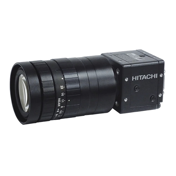
High pixel CMOS camera
KP-FM500WCL
KP-FMD500WCL
Operation Manual
Thank you for purchase this fine Hitachi Kokusai Electric CMOS camera.
Before using the camera, please read this operation manual carefully.
Hitachi Kokusai Electric Inc.
RoHS Compliant
These products comply with the requirement of the RoHS (Restriction of the
use of Certain Hazardous Substances in Electrical and electronic Equipment)
Directive 2002/95/EC.
The first edition in August, 2018.
Advertisement
Table of Contents

Related Manuals for Hitachi KP-FM500WCL


Summary of Contents for Hitachi KP-FM500WCL
- Page 1 High pixel CMOS camera KP-FM500WCL KP-FMD500WCL Operation Manual Thank you for purchase this fine Hitachi Kokusai Electric CMOS camera. Before using the camera, please read this operation manual carefully. Hitachi Kokusai Electric Inc. RoHS Compliant These products comply with the requirement of the RoHS (Restriction of the use of Certain Hazardous Substances in Electrical and electronic Equipment) Directive 2002/95/EC.
- Page 2 IMPORTANT SAFETY INSTRUCTIONS 1. Read Instructions All the safety and operating instructions should be read before the product is operated. 2. Retain Instructions The safety and operating instructions should be retained for future reference. 3. Heed Warnings All warnings on the product and the operating instructions should be adhered to. 4.
- Page 3 WICHTIGE SICHERHEITSANWEISUNGEN 1. Alle Anweisungen lesen Vor Betrieb des Erzeugnisses sollten alle Sicherheits-und Bedienungsanleitungen gelesen werden. 2. Die Anweisungen aufbewahren Die Sicherheits-und Bedienungsanleitungen sollten fünftigen Bezug aufbewahrt werden. 3. Warnungen beachten Die Warnungen auf dem Erzeugnis und in den Bedienungsanleitungen solten beachtet werden. 4.
- Page 4 MISES EN GARDE IMPORTANTES 1. Lire les instructions Lire toutes les instructions de sécurité et de fonctionnement avant de faire fonctionner l’appareil. 2. Conserver ces instructions Conserver les instructions de sécurité et de fonctionnement á des fins de référence ultérieure. 3.
- Page 5 Operation of this product in a residential area is likely to cause harmful interference in which case the user will be required to correct the interference at his own expense. WARNING Changes or modifications not expressly approved by Hitachi Kokusai responsible for compliance could void the user’s authority to operate the equipment. For Canada This product does not exceed the class A/class B limits for radio noise emissions from digital apparatus as set out in the radio interference regulations.
- Page 7 ・ Stop using the camera at the approach of electrical storm (thunder audible). Protect the camera from rain if using it outdoors. ・ In event the camera shows any abnormality, switch off the camera and disconnect the power cord. Contract a Hitachi Kokusai Electric service representative.
- Page 8 5)Monochrome reversing When taking picture of personally strong light, the part where white is saturated might become CMOS element with a black image. Please adjust quantities of light at such time. 6)Horizontal pull phenomenon of image Subject might became bright when there is strong light (strong reflection of the light, the fluorescent lamp, and sunlight etc.) next to subject.
-
Page 9: Table Of Contents
Table of Contents 1. Overview ······················································································································ 1 2. Standard Composition ····································································································· 1 3. Features ······················································································································· 1 4. System example ············································································································ 2 5. Section name and functions ····························································································· 2 6. Camera mounting ··········································································································· 3 7. Lens ···························································································································· 3 8. Optical filter ··················································································································· 3 9. -
Page 10: Overview
Overview KP-FM500WCL are Camera Link output type black and white camera which utilized the 2/3 –inch progressive scan CMOS image sensor with square pixel. KP-FMD500WCL are RAW data output type. The high resolution image of five million pixels is output in no interlace by 163 frames per second. -
Page 11: System Example
System example KP-FM500WCL and KP-FMD500WCL connect to frame grabber board using Camera Link cable. HITACHI Power over type Mini-Camera Link cable (x2 when Medium/Full/Deca configuration) Mini-Camera Link cable Power over type Camera Link (x2 when Medium/Full/Deca configuration) frame grabber board... -
Page 12: Camera Mounting
Camera mounting Attached optional accessory the tripod adaptor "TA-FM200", mount the camera to a tripod or mounting bracket. Screw type: U1/4-20 Length L = 4 to 5.5mm Screws longer than 5.5 mm can cause internal damage, while less than 4 mm prevents secure fastening and risks dropping to cause damage and injury. -
Page 13: Connector
Connector 1. Camera Link connector D.OUT1 (Connector 1) Pin No. Signal Pin No. Signal +12V (PoCL) GND (non-PoCL) TXOUT 0 (-) TXOUT 0 (+) TXOUT 1 (-) TXOUT 1 (+) TXOUT 2 (-) TXOUT 2 (+) TXCLKOUT (-) TXCLKOUT (+) TXOUT 3 (-) TXOUT 3 (+) RX (+) [ SERTC (+) ]... - Page 14 2. DCIN/SYNC connector PIN NO. Signal PIN NO. Signal Trigger INPUT N.U. (PoCL) +12V (non-PoCL) N.U. N.U. FLASH OUT / VD OUT N.U. N.U. N.U.: Not Used Connector (camera side) : SNH-10-12(RPCB) SAMWOO or equivalent Plug (matching cable plug) : HR10A-10P-12S HIROSE or equivalent (Note) Please do not unplug and insert cable (digital out cable) with a power supplied to a camera.
-
Page 15: Functions And Operations
Functions and operations Various mode setup and adjustment of KP-FM500WCL and KP-FMD500WCL are performed by the remote control via Camera Link. Operation and adjustment way of function utilized are described below. See "Remote control" and "Command list" (page 9 to 18) about communication method of each command. - Page 16 (5) CONFIG : Setting of Camera Link configuration BASE(Factory setting) : Camera Link configuration is set to Base configuration. MEDIUM : Camera Link configuration is set to Medium configuration. FULL : Camera Link configuration is set to Full configuration. DECA : Camera Link configuration is set to Deca(10TAP) configuration.
- Page 17 (13) BLACK LEVEL : Adjustment of offset level 0/255(Factory setting) ~ 127/255 : Offset level is set by 128 steps.(Factory setting : 0/255) (14) PARTIAL SCAN : Setting of partial scanning ①MODE : Setting of partial scan OFF(Factory setting) : partial scanning is OFF. : partial scanning is set.
-
Page 18: Remote Control
Remote control 1. Comms* specifications ・Control system : Start-stop synchronization system ・Transmission rate : 115200 bps ・Data length : 8 bit ・Star bit : 1 bit ・Stop bit : 1 bit ・Parity : None ・Bit transfer : LSB first *Comms: Communications 2. - Page 19 HITACHI ACK code (06h) Transmit data (ASCII code) Slave ACK code (06h) (KP-FM500WCL KP-FMD500WCL) Master (Machine) ① Session starts when ENQ is sent from master to slave. ② Slave acknowledges by returning ACK to master. ③ Master sends data to slave.
- Page 20 ENQ code (05h) HITACHI NACK code (15h) ENQ code (05h) Slave NACK code (15h) (KP-FM500WCL ENQ code (05h) KP-FMD500WCL) Master (Machine) NACK code (15h) ① Master sends ENQ code to slave. ② Since ACK code cannot be sent, slave sent NACK code to master.
- Page 21 ACK code (06h) Send data (ASCII code) HITACHI 3 second elapse Send data (ASCII code) Slave 3 second (KP-FM500WCL elapse Send data (ASCII code) KP-FMD500WCL) Master (Machine) 3 second elapse Send data (ASCII code) ① Session starts when ENQ is sent from master to slave.
- Page 22 (6) Transmission frame error (Master receive) ENQ code (05h) ACK code (06h) Read command (ASCII code) HITACHI ACK code (06h) Read data (ASCII code) Slave (KP-FM500WCL 3 second elapse KP-FMD500WCL) Read data (ASCII code) Master (Machine) 3 second elapse Read data (ASCII code)
- Page 23 2 byte (ASCII code) Used for EEPROM write (“00”: write absent, “01”: write present). ・ID No. : Camera peculiar ID. KP-FM500WCL and KP-FMD500WCL have (“FF”). 2 byte (ASCII code) ・Area address : Classification of Send data (“01”) and Read command (“81”).
- Page 24 (2) Read (receive) data (slave to master) (a) Command data are converted into ASCII code and transmitted. (b) Comms byte quantity is 10. (c) Comms data format (transmission sequence) Text data 1 byte 6 byte 1 byte 2 byte 10 byte ・STX (start code) : Code indicating start of text.
-
Page 25: Command List
(*2) VARIABLE VALUE can be set only when VARIABLE is selected. It can be set within the range of 0000h to FFFFh . (*3) Binning function is only KP-FM500WCL. (*4) Gain can be set within the range of 00h to B4h . - Page 26 Item AREA RELATIVE STATUS ID NO. DATA ADDRESS “01” “FF” “01” “1E” “00” “00” “00” “16” MODE “01” “FF” “01” “1E” “01” “00” “00” “15” PARTIAL START(2Byte “01” “FF” “01” “1F” “00” “01” “00” “14” SCAN 2045 “01” “FF” “01” “1F”...
- Page 27 “2B” “00” “00” “00” “11” TEMPERATURE “00” “FF” “81” “62” “00” “00” “00” “1D” (*1)Binning function is only KP-FM500WCL. (*2)WHITE BALANCE function is only KP-FMD500WCL. Read data from the slave follows “4. Comms command data format(2)”(page 15) of “Remote control”.
-
Page 28: Camera Link Output Timing Chart
Camera Link output timing chart 1. Horizontal timing (1) 85MHz Base Configuration (1 clk = 11.765 ns) 1224 clk 2~5 clk LVAL ・ ・ ・ ・ ・ ・ ・ ・ ・ ・ ・ ・ DATA Active Picture ・ ・ ・ ・ ・... - Page 29 (5) 85MHz Full configuration (1 clk = 11.765 ns) 306 clk 2~5 clk LVAL ・ ・ ・ ・ ・ ・ ・ ・ ・ ・ ・ ・ ・ ・ ・ ・ ・ ・ ・ ・ ・ ・ ・ ・ ・ ・ ・ ・ ・...
- Page 30 (7) 85MHz Deca(10TAP) Configuration (1 clk = 11.765 ns) 245 clk 2~5 clk LVAL ・ ・ ・ ・ ・ ・ ・ ・ ・ ・ ・ ・ ・ ・ ・ ・ ・ ・ ・ ・ ・ ・ ・ ・ ・ ・ ・ ・ ・...
- Page 31 2048H (When partialscan is ON, the width) FVAL DATA Active (2) BINNING: ON (* This function is only KP-FM500WCL. 1024H (When partialscan is ON, the width dividing 2) FVAL DATA Active Picture 1 horizontal period differs depending on the configuration and clock frequency setting.
- Page 32 3. Transmitter LVDS output pulse position measurement (1)Base Configuration (a)8bit D.OUT1 11.765 ns (85MHz) or 16.667ns (60MHz) TXCLKOUT Previous Cycle Next Cycle TXOUT 3 DA7-1 DA6-1 N.U. N.U. N.U. TXOUT 2 N.U. N.U. N.U. FVAL LVAL N.U. N.U. N.U. N.U. TXOUT 1 DB2-1 DB1-1...
- Page 33 (c)12bit D.OUT1 11.765 ns (85MHz) or 16.667ns (60MHz) TXCLKOUT Previous Cycle Next Cycle TXOUT 3 DA7-1 DA6-1 N.U. DB11 DB10 DB3-1 DB2-1 N.U. FVAL LVAL TXOUT 2 DA10-1 DA9-1 DA11 DA10 TXOUT 1 DA1-1 DA0-1 TXOUT 0 N.U.: Not Used * When using Base configuration, please be sure to connect to CameraLink cable to D.OUT1.
- Page 34 (2)Medium Configuration (a)8bit D.OUT1 11.765 ns (85MHz) or 16.667ns (60MHz) TXCLKOUT Previous Cycle Next Cycle TXOUT 3 DA7-1 DA6-1 N.U. TXOUT 2 DC3-1 DC2-1 N.U. FVAL LVAL TXOUT 1 DB2-1 DB1-1 TXOUT 0 DA1-1 DA0-1 N.U.: Not Used D.OUT2 11.765 ns (85MHz) or 16.667ns (60MHz) TYCLKOUT Previous Cycle Next Cycle...
- Page 35 (b)10bit D.OUT1 11.765 ns (85MHz) or 16.667ns (60MHz) TXCLKOUT Previous Cycle Next Cycle TXOUT 3 DA7-1 DA6-1 N.U. N.U. N.U. TXOUT 2 DB3-1 DB2-1 N.U. FVAL LVAL TXOUT 1 N.U. DA9-1 N.U. N.U. TXOUT 0 DA1-1 DA0-1 N.U.: Not Used D.OUT2 11.765 ns (85MHz) or 16.667ns (60MHz) TYCLKOUT...
- Page 36 (c)12bit D.OUT1 11.765 ns (85MHz) or 16.667ns (60MHz) TXCLKOUT Previous Cycle Next Cycle TXOUT 3 DA7-1 DA6-1 N.U. DB11 DB10 TXOUT 2 DB3-1 DB2-1 N.U. FVAL LVAL TXOUT 1 DA10-1 DA9-1 DA11 DA10 TXOUT 0 DA1-1 DA0-1 N.U.: Not Used D.OUT2 11.765 ns (85MHz) or 16.667ns (60MHz) TYCLKOUT...
- Page 37 (3)Full Configuration (a)8bit D.OUT1 11.765 ns (85MHz) or 16.667ns (60MHz) TXCLKOUT Previous Cycle Next Cycle TXOUT 3 DA7-1 DA6-1 N.U. TXOUT 2 DC3-1 DC2-1 N.U. FVAL LVAL TXOUT 1 DB2-1 DB1-1 TXOUT 0 DA1-1 DA0-1 N.U.: Not Used 11.765 ns (85MHz) or 16.667ns (60MHz) D.OUT2 TYCLKOUT Previous Cycle...
- Page 38 (b)10bit 11.765 ns (85MHz) or 16.667ns (60MHz) D.OUT1 TXCLKOUT Previous Cycle Next Cycle TXOUT 3 DA9-1 DA8-1 TXOUT 2 DC5-1 DC4-1 FVAL LVAL TXOUT 1 DB4-1 DB3-1 TXOUT 0 DA3-1 DA2-1 N.U.: Not Used 11.765 ns (85MHz) or 16.667ns (60MHz) D.OUT2 TYCLKOUT Previous Cycle...
- Page 39 (4)Deca(10TAP) Configuration (a)8bit 11.765 ns (85MHz) or 16.667ns (60MHz) D.OUT1 TXCLKOUT Previous Cycle Next Cycle TXOUT 3 DA5-1 DD1-1 TXOUT 2 DC4-1 DC3-1 FVAL LVAL TXOUT 1 DB1-1 DB0-1 TXOUT 0 DA1-1 DA0-1 N.U.: Not Used 11.765 ns (85MHz) or 16.667ns (60MHz) D.OUT2 TYCLKOUT Previous Cycle...
- Page 40 4. Output sequence DA, DB, DC, DD, DE, DF, DG, DH, DI and DJ show output TAP of the cameralink. Refer to “Transmitter LVDS output pulse position measurement“ for details. (1) Base Configuration 2448 pixels 2048 lines (2) Medium Configuration 2448 pixels 2048 lines...
- Page 41 (3) Full Configuration 2448 pixels 2048 lines (4) Deca Configuration (10TAP) 2448 pixels 2048 lines...
- Page 42 (5). Color Output sequence(KP-FMD500WCL) *FLIP:OFF 2448 pixels ・ ・ ・ ・ ・ ・ ・ ・ ・ ・ ・ ・ ・ ・ ・ ・ ・ ・ ・ ・ ・ ・ ・ ・ ・ ・ ・ ・ ・ ・ ・ 2048 ・ lines ・...
-
Page 43: Trigger Operation And Timing Chart
Trigger operation and timing chart 1 horizontal period differs depending on the configuration and clock frequency setting. CameraLink output 1horizontal period Base Configuration 85MHz 1H = 14.438us Base Configuration 60MHz 1H = 20.458us Medium Configuration 85MHz 1H = 7.246us Medium Configuration 60MHz 1H = 10.163us Full Configuration 85MHz 1H = 3.636us... - Page 44 Frame rate can be calculated from following equations using width of picture grabbing. Cameralink output setting Frame rate(fps) Base Configuration 85MHz 74250000/(Width+46)/1072 Base Configuration 60MHz 74250000/(Width+46)/1519 Medium Configuration 85MHz 74250000/(Width+46)/538 Medium Configuration 60MHz 74250000/(Width+46)/762 Full Configuration 85MHz 74250000/(Width+46)/270 Full Configuration 60MHz 74250000/(Width+46)/383 Deca(10TAP)...
- Page 45 (2). Fixed shutter mode When trigger polarity setting is , after the trigger signal rise, exposure is start. The exposure time is set by POSITIVE the camera electronic shutter speed. The video output is obtained immediately after the end of fixed exposure. (a) Partial scan : OFF More than 5us More than 2094H...
- Page 46 (3). ONE trigger mode When trigger polarity setting is , after the trigger signal rise, exposure is start. POSITIVE Exposure is terminated at the falling edge of the trigger, and video data is output. (a) Partial scan : OFF More than 5us More than 2094H High Trigger input...
-
Page 47: Input / Output Signal
(2) Input from DCIN/SYNC connector High level : +2.5 to +5.0 V Low level 0 to +0.3 V 2. Output signal The level of the VD and FLASH output from KP-FM500WCL and KP-FMD500WCL is as follows. High level : +5.0V Low level : 0V... -
Page 48: Spectral Response
Spectral response Spectral response of KP-FM500WCL and KP-FMD500WCL are showing. 1. KP-FM500WCL 950 1000 Wave Length [nm] 2. KP-FMD500WCL IR-CUT Filter 950 1000 Wave length [nm]... -
Page 49: Specifications
Specifications KP-FMD500WCL KP-FM500WCL Imaging device 2/3 inch global shutter method CMOS Effective pixels 2448 (H) x 2048 (V) Pixel size 3.45μm (H) x 3.45μm (V) Color filter None RGB primary color mosaic filter Image area 8.45mm (H) x 7.07mm (V) -
Page 50: Dimensions
Dimensions UNIT:mm SCALE:NTS... - Page 51 São Paulo, 01419-001, SP –Brazil Phone: +55(11)3541-3244, Fax: +55(11)3541-2425 URL: http://www.hitachi-linear.com.br/ Hitachi Kokusai Electric Turkey Elektronik Ürünleri Sanayi ve Ticaret A.Ş. : Istanbul Deri OSB Ⅷ-5 Parsel No.1, 34953 Tuzla Istanbul, Turkey Head Office Tuzla Branch : Istanbul Endüstri ve Ticaret Serbest Bölgesi, Akif Kopuz Cad.
Need help?
Do you have a question about the KP-FM500WCL and is the answer not in the manual?
Questions and answers