Table of Contents
Advertisement
Quick Links
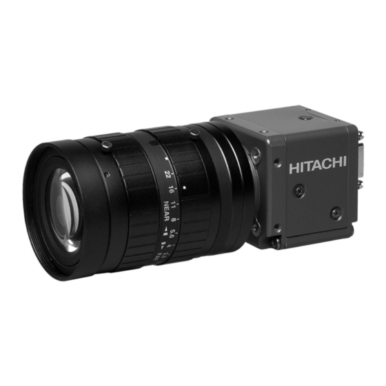
High pixel CCD camera
KP-F500PCL/SCL
O p e r a t i o n M a n u a l
Thank you for purchase this fine Hitachi Kokusai
Electric CCD camera.
Before using the camera, please read this operation
manual carefully and keep this manual on file for
ready reference in the future.
Hitachi Kokusai Electric Inc.
RoHS Compliant
These products comply with the requirement of the
RoHS (Restriction of the use of Certain Hazardous
Substances
in
Electrical
Equipment) Directive 2002/95/EC.
and
electronic
Advertisement
Table of Contents

Subscribe to Our Youtube Channel
Related Manuals for Hitachi KP-F500PCL


Summary of Contents for Hitachi KP-F500PCL
- Page 1 KP-F500PCL/SCL O p e r a t i o n M a n u a l RoHS Compliant Thank you for purchase this fine Hitachi Kokusai These products comply with the requirement of the Electric CCD camera. RoHS (Restriction of the use of Certain Hazardous...
-
Page 3: Important Safety Instructions
IMPORTANT SAFETY INSTRUCTIONS 1. Read Instructions All the safety and operating instructions should be read before the product is operated. 2. Retain Instructions The safety and operating instructions should be retained for future reference. 3. Heed Warnings All warnings on the product and the operating instructions should be adhered to. 4. - Page 4 Unplug this product from the wall outlet and refer servicing to qualified service personnel under the following conditions: a.When the power-supply cord or plug is damaged. b.If liquid has been spilled, or objects have fallen into the product. c. If the product has been exposed to rain or water. d.If the product does not operate normally by following the operating instructions.
- Page 5 Dieses Erzeugnis sollte nur an der auf dem Typenschild angegebenen Stromversorgungsart betrieben werden. Wenn Sie nicht sicher sind, was für eine Stromversorgung Sie haben, so wenden Sie sich bitte an Ihren Erzeugnishändler oder an das lokale Elektrizitätswerk. Beziehen Sie sich für Batteriebetrieb oder andere Stromquellen vorgesehene Erzeugnisse bitte auf die Bedienungsanleitungen.
- Page 6 2. Conserver ces instructions Conserver les instructions de sécurité et de fonctionnement á des fins de référence ultérieure. 3. Tenir compte des avertissements Tous les avertissements qui figurent sur l’appareil et dans le mode d’emploi devront être respectés. 4. Observer les instructions Observer toutes les instructions de fonctionnement et d’utilisation.
-
Page 7: Important Notice
WARNING Changes modifications not expressly approved by Hitachi Denshi responsible for compliance could void the user’s authority to operate the equipment. - Page 8 ・ Sop using the camera at the approach of electrical storm (thunder audible). Protect the camera from rain if using it outdoors. ・ In event the camera shows any abnormality, switch off the camera and disconnect the power cord. Contract a Hitachi Denshi service representative.
- Page 9 6. Cleaning ・ Use a blower or a lens brush to remove dusts on the lens or the optical filter. ・ Wipe dirts on the case off with dry soft cloth. If dirks are hardened, wipe them off with cloth moistened with neutral detergent liquid;...
-
Page 10: Table Of Contents
Table of Contents 1. Overview ······································································································································································································ 1 2. Standard Composition ··········································································································································································· 1 3. Features ······································································································································································································· 1 4. System example ······················································································································································································· 1 5. Section name and functions ······························································································································································· 2 6. Camera mounting ····················································································································································································· 2 7. Lens ··············································································································································································································· 2 8. Optical filter ······························································································································································································· 3 9. -
Page 11: Overview
Overview KP-F500PCL/SCL are CameraLink output type black and white camera which utilized the 2/3 –inch progressive scan CCD image sensor with square pixel. It provide images of unparalleled quality at 16 frame per second non-interlaced output. Since KP-F500PCL is power over CL type, PC can provide power to camera passed CameaLink cable. -
Page 12: Section Name And Functions
Section name and functions Camera / Tripod adaptor mounting screw holes CameraLink connectors Use for digital video output Lens mount and camera control signal (C mount) input/output signal. DC IN/SYNC connector Use for DC+12V power (KP-F500SCL) or external trigger/VD signal input. Camera / Tripod adaptor mounting screw holes Camera mounting... -
Page 13: Optical Filter
Optical filter How to remove the IR cut filter. (1) Remove two screws ① and filter holder ② will come off. (2) Remove the IR cut filter ③ from filter frame ④. (3) Then, reinstall and secure filter holder ② with two screws ①. Note: Prior to removing the optical filter, be sure to turn off the power. -
Page 14: Connector
Connector 1. CameraLink connector D.OUT1 (Connector 1) Pin No. Signal Pin No. Signal +12V (KP-F500PCL) GND (KP-F500SCL) TXOUT 0 (-) TXOUT 0 (+) TXOUT 1 (-) TXOUT 1 (+) TXOUT 2 (-) TXOUT 2 (+) TXCLKOUT (-) TXCLKOUT (+) TXOUT 3 (-) TXOUT 3 (+) -
Page 15: Functions And Operations
Functions and operations Various mode setup and adjustment of KP-F500PCL/SCL are performed by the remote control via CameraLink. Operation and adjustment way of function utilized in KP-F500PCL/SCL are described below. See "Remote control" (page 7 to 15) about communication method of each command. - Page 16 Ex.1 Exposure time = setting value nnn to obtain 1/125 second (= 8000μsecond). − 8000 ⎛ ⎞ ⎛ ⎞ 8000 ⎜ ⎜ ⎟ ⎟ − × ⎜ ⎟ ⎝ ⎠ ⎝ ⎠ ⎛ ⎞ × ⎜ ⎟ ⎝ ⎠...
-
Page 17: Remote Control
Remote control 1. Comms* specifications ・Control system : Start-stop synchronization system ・Transmission rate : 9600 bps ・Data length : 8 bit ・Star bit : 1 bit ・Stop bit : 1 bit ・Parity : None ・Bit transfer : LSB first *Comms: Communications 2. - Page 18 ACK code (06H) HITACHI Transmit data (ASCII code) ACK code (06H) Slave (KP-F500PCL/SCL) Master (PC) ① Session starts when ENQ is sent from master to slave. ② Slave acknowledges by returning ACK to master. ③ Master sends data to slave.
- Page 19 HITACHI NACK code (15H) ENQ code (05H) Slave NACK code (15H) (KP-F500PCL/SCL) ENQ code (05H) Master (PC) NACK code (15H) ① Master sends ENQ code to slave. ② Since ACK code cannot be sent, slave sent NACK code to master.
- Page 20 Send data (ASCII code) HITACHI 3 second elapse Send data (ASCII code) Slave 3 second (KP-F500PCL/SCL) elapse Send data (ASCII code) Master (PC) 3 second elapse Send data (ASCII code) ① Session starts when ENQ is sent from master to slave.
- Page 21 (6) Transmission frame error (Master receive) ENQ code (05H) ACK code (06H) Read command (ASCII code) HITACHI ACK code (06H) Read data (ASCII code) Slave 3 second (KP-F500PCL/SCL) elapse Read data (ASCII code) Master (PC) 3 second elapse Read data (ASCII code) 3 second elapse Read data (ASCII code) ①...
- Page 22 2 byte (ASCII code) Used for EEPROM write (0: write absent, 1: write present). ・ID No. : Camera peculiar ID. KP-F500PCL/SCL has (FFH). 2 byte (ASCII code) ・Area address : Sets number (0 to 255) for each adjustment item. 2 byte (ASCII code) ・Relative No.
- Page 23 (2) Read (receive) data (slave to master) (a) Command data are converted into ASCII code and transmitted. (b) Comms byte quantity is 10. (c) Comms data format (transmission sequence) S T X Text data E T X S U M 1 byte 6 byte 1 byte...
-
Page 24: Command List
Command list 1. Setting command data (Note: 1 to 7 and SUM need to be transformed into ASCII code) Item ETX SUM AREA RELATIVE STATUS ID NO. DATA ADDRESS FIXED MODE 1TRIG VD CONT TRIGGER POSITIVE POLARITY NEGATIVE CL-CC1 SOURCE 12pin OUTPUT SIGNAL FLASH OUT... - Page 25 2. Read-out command data (Note: 1 to 7 and SUM need to be transformed into ASCII code) Item AREA RELATIVE STATUS ID NO. DATA ADDRESS MODE TRIGGER POLARITY PRESET SHUTTER SPEED VARIABLE VALUE CONFIGURATION DATA BIT VD / FVAL HD / LVAL GAIN BLACK LEVEL VERTICAL 2 PIXEL ADDITION...
-
Page 26: Cameralink Output Timing Chart
CameraLink output timing chart 1. Horizontal timing 1924 clk 100 clk 316 clk 280 clk 1228 clk VIDEO Active Picture LVAL 1 clk = 15.625 ns 2. Vertical timing 2079 H 10 H 2058 H VIDEO Active Picture FVAL 1 H = 1924 clk = 30.0625 μs * Vertical timing for vertical 2 pixel addition mode 1040 H 1029 H... - Page 27 3. Transmitter LVDS output pulse position measurement (1) Base Configuration (a) 8bit D.OUT1 15.625ns (64MHz) CLKX Previous Cycle Next Cycle 1.41V DA7-1 DA6-1 1.075V FVAL LVAL (VD) (HD) DB2-1 DB1-1 DA1-1 DA0-1 0±3ns (b) 10bit D.OUT1 15.625ns (64MHz) CLKX Previous Cycle Next Cycle 1.41V DA7-1...
- Page 28 (c) 12bit D.OUT1 15.625ns (64MHz) CLKX Previous Cycle Next Cycle 1.41V DA7-1 DA6-1 DB11 DB10 1.075V DB3-1 DB2-1 FVAL LVAL (VD) (HD) DA10-1 DA9-1 DA11 DA10 DA1-1 DA0-1 0±3ns When using at Base configuration, please be sure to connect CameraLink cable to D.OUT1. If the cable is connected to D.OUT2, machine may break down.
- Page 29 (2) Medium Configuration (a) 8bit D.OUT1 31.25ns (32MHz) CLKX Previous Cycle Next Cycle 1.41V DA7-1 DA6-1 1.075V DC3-1 DC2-1 FVAL LVAL (VD) (HD) DB2-1 DB1-1 DA1-1 DA0-1 0±3ns D.OUT2 31.25ns (32MHz) CLKY Previous Cycle Next Cycle 1.41V 1.075V FVAL LVAL (VD) (HD) DD1-1...
- Page 30 (b) 10bit D.OUT1 31.25ns (32MHz) CLKX Previous Cycle Next Cycle 1.41V DA7-1 DA6-1 1.075V DB3-1 DB2-1 FVAL LVAL (VD) (HD) DA9-1 DA1-1 DA0-1 0±3ns D.OUT2 31.25ns (32MHz) CLKY Previous Cycle Next Cycle 1.41V DD7-1 DD6-1 1.075V FVAL LVAL (VD) (HD) DC2-1 DC1-1 DD1-1...
- Page 31 (c) 12bit D.OUT1 31.25ns (32MHz) CLKX Previous Cycle Next Cycle 1.41V DA7-1 DA6-1 DB11 DB10 1.075V DB3-1 DB2-1 FVAL LVAL (VD) (HD) DA10-1 DA9-1 DA11 DA10 DA1-1 DA0-1 0±3ns D.OUT2 31.25ns (32MHz) CLKY Previous Cycle Next Cycle 1.41V DD7-1 DD6-1 DD11 DD10 1.075V...
- Page 32 4. Output sequence It shows KP-F500PCL/SCL output sequence of image data. X = H/2 H = 2456 V = 2058 (a) Base Configuration : Data of screen left half. This means that left to the x-th pixel on y-th line.
-
Page 33: Trigger Operation And Timing Chart
4H when vertical two pixel addition. *3:When partial scan, variable by set width of picture grabbing. 1029H when vertical two pixel addition. Graph following shows frame rate in each of picture grabbing in the partial scan mode. KP-F500PCL/SCL Partial scan 1000 1500 2000... - Page 34 2. Fixed shutter mode When external trigger signal is high active, after the trigger signal rise, exposure is start. The exposure time is set by the camera electronic shutter speed. The video output is obtained immediately after the end of fixed exposure. The strobe signal start/end can be set to shutter time.
- Page 35 4. VD reset When external VD pulse is inputted, internal HD/VD is reset. External VD specification: 16.00 Hz or less *Note: When external VD of 16.00 Hz or more is input, electronic shutter has an equation between external VD and 16.00 Hz. VD input High (Low active)
-
Page 36: Spectral Response
Spectral response Spectral response of KP-F500PCL/SCL is showing. IR cut filter 1000 Wave Length (nm) -
Page 37: Specifications
Specifications Specifications of KP-F500PCL/SCL are showing. KP-F500PCL/SCL Imaging device 2/3-inch interline CCD Total pixels 2536 (H) x 2068 (V) Effective pixels 2456 (H) x 2058 (V) Active pixels 2448 (H) x 2050 (V) Pixel pitch 3.45μm (H) x 3.45μm (V) Image area 9.93mm (H) x 8.70mm (V) -
Page 38: Dimensions
Dimensions MASS: APPROX 110 g ±0.5 ±1 10.5 3×2-M3(DEPTH:3) 34 2-M2(DEPTH:3) ±0.5 44 ±0.5 ±1.5 28 4-M3(DEPTH:6) 47 ±0.5 0.5 22 6 40.5 D.OUT 1 D.OUT 2 DC IN/SYNC COLOR:BLACK COLOR:BLACK ±1 10.5 2-M3(DEPTH:3) 34 2-M2(DEPTH:3) mm UNIT:... -
Page 39: About Cd-Rom
① The included control software within CD-ROM operate only in Windows 98/Me/NT/2000/XP. ② The control software may not operate normal when it is used for the other camera, because software for Hitachi Kokusai Electric. ③ Hitachi Kokusai Electric Inc. does not guarantee regarding the faulty, damage of the hardware and also software of the... - Page 40 : phone (+1) 516-682-4435, Fax: (+1) 516-921-0993 Latin Sales : phone (+1) 519-682-4420, Fax: (+1) 516-496-3718 URL: http://www.hdal.com/ Hitachi Kokusai Electric Europe GmbH Head Office : Weiskircher Strasse 88, Jugesheim D-63110 Rodgau, Germany Phone: +49(0) 6106-6992-0, Fax: +49(0) 6106-1690-6 URL: http://www.hitachi-ke-eu.com/ Hitachi Kokusai Electric U.K.
Need help?
Do you have a question about the KP-F500PCL and is the answer not in the manual?
Questions and answers