Table of Contents
Advertisement
Quick Links
Advertisement
Table of Contents

Related Manuals for IBASE Technology ET910


Summary of Contents for IBASE Technology ET910
- Page 1 ET910 Intel Core Duo/Solo 945GM ® ETX CPU Module USER’S MANUAL Version 1.0...
- Page 2 Intel and Celeron are registered trademarks of Intel Corporation. Microsoft Windows is a registered trademark of Microsoft Corporation. Winbond is a registered trademark of Winbond Electronics Corporation. All other product names or trademarks are properties of their respective owners. ET910 User’s Manual...
-
Page 3: Table Of Contents
Introduction ............1 Product Description............. 1 Checklist ................2 Specifications ..............3 Dimensions ................4 Connector Locations on ET910 .......... 5 Installing the CPU ............... 6 Installing the Memory ............8 Connector Pin Assignments ..........9 BIOS Setup ............13 Drivers Installation ........ - Page 4 The ET910 945GM ETX CPU Module ET910 User’s Manual...
-
Page 5: Introduction
Intel Centrino mobile technology. In addition, the Intel 945GM chipset provides integrated graphics (350 MHz) capabilities and power saving features. Below are the main features of the ET910 ETX CPU module. Support Intel® Core™2 Duo/ Core™ Duo Processor ... -
Page 6: Checklist
INTRODUCTION Checklist Your ET910 package should include the items listed below. The ET910 CPU Module This User’s Manual 1 CD containing the following: Chipset Drivers Flash Memory Utility Serial ATA cable ET910 User’s Manual... -
Page 7: Specifications
Hirose FX8-100P-SV ETX connector x4 for PCI bus, USB, Carrier Board audio, VGA/CRT, LVDS, LAN, COM ports, parallel port, IDE, PS/2 Keyboard/Mouse & ISA bus Power +5V, 5VSB & 3V for RTC RoHS Compliant Board Size 95mm x 114mm ET910 User’s Manual... -
Page 8: Dimensions
INTRODUCTION Dimensions ET910 User’s Manual... -
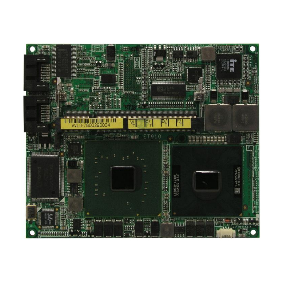
Page 9: Connector Locations On Et910
INTRODUCTION Connector Locations on ET910 (top view) ET910 User’s Manual... -
Page 10: Installing The Cpu
INTRODUCTION Installing the CPU The ET910 module supports a Socket 478MT (Napa) processor socket for Intel® Core 2 Duo , Intel® Core Duo and Intel® Core Solo mobile processors. The processor socket comes with a screw to secure the processor. As shown in the left picture below, loosen the screw first before inserting the processor. - Page 11 Before installing the heatsink, the four (4) pieces of protective sheaths on the thermal pads should be removed first. Please refer to the following pictures: Chipset thermal pad 1 Chipset thermal pad 2 CPU thermal pad 1 CPU thermal pad 2 ET910 User’s Manual...
-
Page 12: Installing The Memory
INTRODUCTION Installing the Memory The ET910 supports one SODIMM DDR memory socket for a maximum total memory of 2GB. The memory module capacities supported are 128MB, 256MB, 512MB 1GB and 2GB. Installing and Removing Memory Modules To install the DDR modules, locate the memory slot on the board and perform the following steps: 1. -
Page 13: Connector Pin Assignments
AD18 AD20 USB00 AD22 AD21 AD23 USB10 CBFJ0 AD24 CBEJ3 AD25 AD26 AD10 AUXAL AD28 USB01 AD11 AD27 AD29 AD12 AUXAR AD30 USB11 AD13 ASVCC PCIRSTJ AD31 AD14 SNDL IRQY IRQZ AD15 ASGND IRQW IRQX CBEJ1 SNDR ET910 User’s Manual... - Page 14 LA17 DACKJ0 SA14 DACKJ3 LA18 IRQ14 SA15 IORJ LA19 IR015 SA16 IOWJ LA20 IRQ12 SA18 SA17 LA21 IRQ11 SA19 SMEMRJ LA22 IRQ10 IOCHRDY LA23 I016J SMEMWJ SBHEJ M16J NOWSJ BALE DREQ2 IRQ9 DACKJ2 IR03 IOCHKJ RSTDRV IRQ4 ET910 User’s Manual...
- Page 15 LCD DO4 LCD DO7 RI2J LCD DO5 LCD DO6 RXD1 /ACK LCD DO1 LCD DO3 RTS1J /BUSY LCD DO0 LCD DO2 DTR1J DCD1J /SLCT LTGIO0 DSR1J MSCLK BLON# CTS1J MSDAT BIASON DIGON TXD1 KBCLK COMP RI1J KBDAT ET910 User’s Manual...
- Page 16 5. CN1, CN2: Serial ATA Connectors. Located just beside the SODIMM memory socket are two serial ATA connectors. 6. FAN1: System Fan Power Connector FAN1 is a 3-pin header for system fans. Pin # Signal Name Ground Ground ET910 User’s Manual...
-
Page 17: Bios Setup
Power Management Setup ............27 PNP/PCI Configurations ............... 29 PC Health Status ................30 Load Fail-Safe Defaults ..............31 Load Optimized Defaults .............. 31 Set Supervisor/User Password ............31 Save & Exit Setup ................. 31 Exit Without Saving ..............31 ET910 User’s Manual... -
Page 18: Bios Introduction
<PgUp> and <PgDn> keys to change entries, <F1> for help and <Esc> to quit. When you enter the Setup utility, the Main Menu screen will appear on the screen. The Main Menu allows you to select from various setup functions and exit choices. ET910 User’s Manual... - Page 19 These defaults have been carefully chosen by both Award and your system manufacturer to provide the absolute maximum performance and reliability. Changing the defaults could cause the system to become unstable and crash in some cases. ET910 User’s Manual...
-
Page 20: Standard Cmos Setup
The following describes each item of this menu. Date The date format is: Day : Sun to Sat Month : 1 to 12 Date : 1 to 31 Year : 1999 to 2099 ET910 User’s Manual... - Page 21 The Access Mode selections are as follows: (HD < 528MB) (HD > 528MB and supports Logical Block Addressing) Large (for MS-DOS only) Auto Remarks: The main board supports two serial ATA ports and are represented in this setting as IDE Channel 0. ET910 User’s Manual...
- Page 22 The system boot will not be halted for a disk error; it will stop for all other errors. All, But Disk/Key The system boot will not be halted for a key- board or disk error; it will stop for all others. ET910 User’s Manual...
-
Page 23: Advanced Bios Features
When the CPU requests data, the system transfers the requested data from the main DRAM into cache memory, for even faster access by the CPU. These allow you to enable (speed up memory access) or disable the cache function. ET910 User’s Manual... - Page 24 When enabled, you can set the two typematic controls listed next. By default, this field is set to Disabled. Typematic Rate (Chars/Sec) When the typematic rate is enabled, the system registers repeated keystrokes speeds. Settings are from 6 to 30 characters per second. ET910 User’s Manual...
- Page 25 OS/2 that depends on certain BIOS calls to access memory. The default setting is Non-OS/2. Small Logo (EPA) Show The EPA logo appears at the right side of the monitor screen when the system is boot up. The default setting is Disabled. ET910 User’s Manual...
-
Page 26: Advanced Chipset Features
This option sets the number of cycles required for the RAS to accumulate its charge before the SDRAM refreshes. The default setting for the Active to Precharge Delay is Auto. Precharge Delay (tRAS) The default setting for the Precharge Delay is Auto. ET910 User’s Manual... - Page 27 These fields allow you to select the LCD Panel type. The default values for these ports are: 640x480 18bit SC 800x480 18bit SC 800x600 18bit SC 1024x768 18bit SC 1280x1024 18bit DC 1280x768 18bit SC 1400x1050 18bit DC 1600x1200 18bit DC ET910 User’s Manual...
-
Page 28: Integrated Peripherals
PATA IDE Mode Secondary SATA port P0, P2 is Primary Phoenix - AwardBIOS CMOS Setup Utility Onboard Device Enabled ITEM HELP USB Controller Enabled Menu Level > USB 2.0 Controller Disabled USB Keyboard Support AC97 Audio Select Auto ET910 User’s Manual... -
Page 29: Ide Hdd Block Mode
When Auto is selected, the BIOS will select the best available mode. IDE Primary/Secondary Master/Slave UDMA These fields allow your system to improve disk I/O throughput to 33Mb/sec with the Ultra DMA/33 feature. The options are Auto and Disabled. ET910 User’s Manual... - Page 30 Normal. Other options include IrDA and ASKIR. Parallel Port Mode This field allows you to determine parallel port mode function. Standard Printer Port Enhanced Parallel Port Extended Capabilities Port ECP+EPP Combination of ECP and EPP capabilities Normal Normal function ET910 User’s Manual...
-
Page 31: Power Management Setup
This field defines the Video Off features. There are three options. V/H SYNC + Blank Default setting, blank the screen and turn off vertical and horizontal scanning. DPMS Allows BIOS to control the video display. Blank Screen Writes blanks to the video buffer. ET910 User’s Manual... - Page 32 When an I/O device wants to gain the attention of the operating system, it signals this by causing an IRQ to occur. When the operating system is ready to respond to the request, it interrupts itself and performs the service. ET910 User’s Manual...
-
Page 33: Init Display First
PCI/VGA. When this field is enabled, a PCI/VGA can work with an MPEG ISA/VESA VGA card. When this field is disabled, a PCI/VGA cannot work with an MPEG ISA/VESA card. Maximum Payload Size The default setting of the PCI Express Maximum Payload Size is 4096. ET910 User’s Manual... -
Page 34: Pc Health Status
Shutdown Temperature This field allows the user to set the temperature by which the system automatically shuts down once the threshold temperature is reached. This function can help prevent damage to the system that is caused by overheating. ET910 User’s Manual... -
Page 35: Load Fail-Safe Defaults
Select this option to exit the Setup utility without saving the changes you have made in this session. Typing “Y” will quit the Setup utility without saving the modifications. Typing “N” will return you to Setup utility. ET910 User’s Manual... - Page 36 BIOS SETUP This page is intentionally left blank. ET910 User’s Manual...
-
Page 37: Drivers Installation
AC97 Codec Audio Driver Installation (IP100 only) ....38 Intel PRO LAN Drivers Installation ........... 40 IMPORTANT NOTE: After installing your Windows operating system (Windows 98SE/ME/2000/XP), you must install first the Intel Chipset Software Installation Utility before proceeding with the drivers installation. ET910 User’s Manual... -
Page 38: Intel Chipset Software Installation Utility
Plug & Play INF support for Intel chipset components. Follow the instructions below to complete the installation under Windows 2000/XP. 1. Insert the CD that comes with the board. Click Intel Chipsets and then Intel(R) I945GM Chipset Drivers. 2. Click Intel(R) Chipset Software Installation Utility. ET910 User’s Manual... - Page 39 4. Click Yes to accept the software license agreement and proceed with the installation process. 5. On Readme Information screen, click Next to continue the installation. 6. The Setup process is now complete. Click Finish to restart the computer and for changes to take effect. ET910 User’s Manual...
-
Page 40: Vga Drivers Installation
To install the VGA drivers, follow the steps below to proceed with the installation. 1. Insert the CD that comes with the board. Click Intel Chipsets and then Intel(R) I945GM Chipset Drivers. 2. Click Intel(R) I945GM Chipset Family Graphics Driver. ET910 User’s Manual... - Page 41 DRIVERS INSTALLATION 3. When the Welcome screen appears, click Next to continue. 4. When the setup is complete, restart the computer as prompted and for changes to take effect. ET910 User’s Manual...
-
Page 42: Ac97 Codec Audio Driver Installation (Ip100 Only)
1. Insert the CD that comes with the board. Click Intel Chipsets and then Intel(R) I945GM Chipset Drivers. 2. Click Realtek Codec Audio Audio Driver. 3. When the screen below appears, click Yes to continue with the installation. ET910 User’s Manual... - Page 43 DRIVERS INSTALLATION 4. Click Finish to restart the computer and for changes to take effect. . ET910 User’s Manual...
-
Page 44: Intel Pro Lan Drivers Installation
1. Insert the CD that comes with the board. Click Intel Chipsets and then Intel(R) I945GM Chipset Drivers. Then, click Intel(R) PRO LAN Network Drivers. 2. Click Install Base Software to continue. 3. When prompted, please to restart the computer for new settings to take effect. ET910 User’s Manual...
Need help?
Do you have a question about the ET910 and is the answer not in the manual?
Questions and answers