
Related Manuals for IBASE Technology IB962AF-165H


Summary of Contents for IBASE Technology IB962AF-165H
- Page 1 IB962 ® 14th Generation Intel Core™ Ultra Processor (MTL-U/H Platform) 3.5" Disk-Size SBC User’s Manual Version 1.0 (August 2024)
- Page 2 No part of this publication may be reproduced, copied, stored in a retrieval system, translated into any language or transmitted in any form or by any means, electronic, mechanical, photocopying, or otherwise, without the prior written consent of IBASE Technology, Inc. (hereinafter referred to as “IBASE”). Disclaimer IBASE reserves the right to make changes and improvements to the products described in this document without prior notice.
- Page 3 Compliance This product has passed CE Class B tests for environmental specifications and limits. This product is in accordance with the directives of the European Union (EU). In a domestic environment, this product may cause radio interference in which case users may be required to take adequate measures.
-
Page 4: Important Safety Information
Important Safety Information Environmental conditions: • Use this product in environments with ambient temperatures between 0˚C and 60˚C. • Do not leave this product in an environment where the storage temperature may be below -20° C or above 80° C. To prevent from damages, the product must be used in a controlled environment. -
Page 5: Warranty Policy
Warranty Policy • IBASE standard products: 24-month (2-year) warranty from the date of shipment. If the date of shipment cannot be ascertained, the product serial numbers can be used to determine the approximate shipping date. • -party parts: 12-month (1-year) warranty from delivery for the 3 -party parts that are not manufactured by IBASE, such as CPU, CPU cooler, memory, storage devices, power adapter, panel and touchscreen. -
Page 6: Table Of Contents
Table of Contents Chapter 1 General Information ..........1 Introduction ..................2 Features ....................2 Packing List ..................3 Optional Accessories ................3 Specifications ..................4 Block Diagram ..................6 Board Pictures ..................7 Dimensions ..................10 Chapter 2 Hardware Configuration ........11 Essential Installations ................ - Page 7 2.5.13 J8: Battery Connector ............29 2.5.14 J9, J13: LVDS CH-B / CH-A ..........30 2.5.15 J10: Digital I/O (4in, 4out) .............31 2.5.16 J11: eSPI Debug (Factory Use Only) ........31 2.5.17 J12: DDR5 SO-DIMM CHB ...........31 2.5.18 J14: M.2 B-Key 3052 ............32 2.5.19 J15: SPI Flash Connector (Factory use only) ......32 2.5.20...
- Page 8 This page is intentionally left blank. viii IB962 User Manual...
-
Page 9: Chapter 1 General Information
Chapter 1 General Information The information provided in this chapter includes: • Features • Packing List • Optional Accessories • Specifications • Block Diagram • Board Pictures • Board Dimensions... -
Page 10: Introduction
Introduction Powered by the latest 14th Gen Intel® Core™ Ultra 7/5 100 Series mobile processors, the IB962 ensures high performance and exceptional efficiency for a wide range of applications. Accompanied by 2x DDR5 SO-DIMM sockets with a maximum capacity of 64GB, the motherboard guarantees seamless multitasking and improved system responsiveness. -
Page 11: Packing List
General Information Packing List Your IB962 package should include the items listed below. If any of the items below is missing, contact the distributor or dealer from whom you purchased the product. • IB962 SBC • Disk (including chipset drivers and flash memory utility) •... -
Page 12: Specifications
Specifications Models IB962AF-165H (Ultra 165H CPU onboard) IB962AF-165U (Ultra 165U CPU onboard) Product Name IB962AF-135H (Ultra 135H CPU onboard) IB962AF-135U (Ultra 135U CPU onboard) ® Intel Core Ultra 100 series (U/H series), 4nm CPU Type BGA-2049 package (50mm x 25mm x 1.35mm), Ultra 7 –... - Page 13 General Information Power +12V (-10% tolerance) ~ Requirement +24V (+10% tolerance) DC-in dTPM/fTPM 102.22 x 147.01 mm (4.02” x 5.8”) Dimensions RoHS 2 Certification CE, FCC Class B I/O Ports • DisplayPort • Display eDP & LVDS • HDMI 2 x RJ45 for 2.5 Gigabit Ethernet •...
-
Page 14: Block Diagram
Block Diagram IB962 User Manual... -
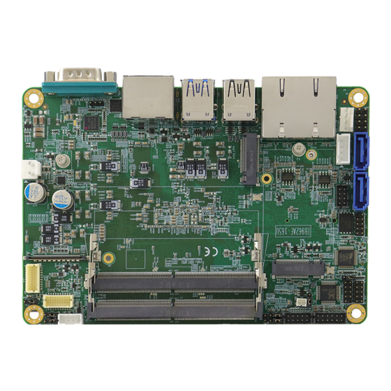
Page 15: Board Pictures
General Information Board Pictures Top View IB962 User Manual... - Page 16 Bottom View IB962 User Manual...
- Page 17 General Information I/O View Function Connector Dual 2.5 GbE Ports USB Ports CN5, CN7 DP++ / HDMI COM1 Serial Port IB962 User Manual...
-
Page 18: Dimensions
Dimensions IB962 User Manual... -
Page 19: Chapter 2 Hardware Configuration
Chapter 2 Hardware Configuration This section provides information on jumper settings and connectors on the IB962 in order to set up a workable system. On top of that, you will also need to install crucial pieces such as the CPU and the memory before using the product. -
Page 20: Essential Installations
Essential Installations 2.1.1 Installing the Memory The IB962 supports TWO memory socket for DDR5 modules. To install a module, locate the memory slot on the board and perform the following steps: Align the key of the memory module with that on the memory slot and insert the module slantwise. -
Page 21: Setting The Jumpers
Hardware Configuration Setting the Jumpers Set up and configure your IB962 by using jumpers for various settings and features according to your needs and applications. Contact your supplier if you have doubts about the best configuration for your use. Jumpers are short-length conductors consisting of several metal pins with a non-conductive base mounted on the circuit board. -
Page 22: Jumper & Connector Locations
Jumper & Connector Locations IB962 User Manual... -
Page 23: Jumpers Quick Reference
Hardware Configuration Jumpers Quick Reference Jumper Function Clear RTC LVDS Brightness Power Selection eDP Power Selection LVDS Power Selection Sierra EM919x 5G card USB/PCIe Select AT/ATX Selection Flash Descriptor Security Override Clear CMOS Data 2.4.1 J1: Clear RTC Function Pin closed Setting Normal Clear RTC... -
Page 24: Jp1: Lvds Brightness Power Selection
2.4.2 JP1: LVDS Brightness Power Selection Function Pin closed Setting 3.3V (default) 2.4.3 JP2: eDP Power Selection Function Pin closed Setting 3.3V (default) IB962 User Manual... -
Page 25: Jp3: Lvds Power Selection
Hardware Configuration 2.4.4 JP3: LVDS Power Selection Function Pin closed Setting 3.3V (default) 2.4.5 JP4: Sierra EM919x 5G card USB/PCIe Select Function Pin closed Setting (default) PCIe IB962 User Manual... -
Page 26: Jp5: At/Atx Select
2.4.6 JP5: AT/ATX Select Function Pin closed Setting Open (default) Close 2.4.7 J5: Flash Descriptor Security Override (Factory use only) 2.4.8 J6: Clear CMOS Function Pin closed Setting Normal Clear CMOS IB962 User Manual... -
Page 27: Connectors Quick Reference
Hardware Configuration Connectors Quick Reference Connectors Function eDP Connector CN2, CN3 SATA #0 / #1 Ports 2.5G LAN i226LM/i226V Ports USB3 #2 / USB2 #2 Ports DP++ /HDMI USB3 TCP#2 #3 COM1 Port SIM Socket Clear RTC LVDS Backligh Connector Audio Connector COM2 Port DDR5 SO-DIMM CHA... - Page 28 IB962 User Manual...
-
Page 29: Cn1: Edp Connector
Hardware Configuration 2.5.1 CN1: eDP Connector Assignment Assignment eDP Vcc TXN0 eDP Vcc TXP1 eDP Vcc Ground eDP Vcc AUXP eDP Vcc AUXN Ground Ground +3.3V Ground EDP BKLT (+12V) Ground Hot Plug detect Ground Ground TXN3 TXP3 Back Light Control Ground Back Light Enable TXN2... -
Page 30: Cn2, Cn3: Sata #0 / Sata #1
2.5.2 CN2, CN3: SATA #0 / SATA #1 Assignment Ground Ground Ground IB962 User Manual... -
Page 31: Cn4: 2.5G Lan I226Lm/I226V
Hardware Configuration 2.5.3 CN4: 2.5G LAN i226LM/i226V 2.5.4 CN5: USB3 #2 / USB2 #2 IB962 User Manual... -
Page 32: Cn6: Dp++ / Hdmi
2.5.5 CN6: DP++ / HDMI 2.5.6 CN7: USB3 TCP#2 #3 IB962 User Manual... -
Page 33: Cn8: Com1 Port
Hardware Configuration 2.5.7 CN8: COM1 Port Assignment RS-232 RS-422 RS-485 DATA- DATA+ Ground Ground Ground IB962 User Manual... -
Page 34: Cn9: Sim Socket
2.5.8 CN9: SIM Socket 2.5.9 J2: LVDS Backlight Connector * E-Call_0110-161-040 Assignment +12V Backlight Enable Brightness Control IB962 User Manual... -
Page 35: J3: Audio Connector
Hardware Configuration 2.5.10 J3: Audio Connector * HK_DF11-12S-PA66H Assignment Assignment LINE OUT_L LINE OUT_R FRONT_JD LINE IN_L LINE IN_R LINE _JD MIC_L MIC_R MIC_JD IB962 User Manual... -
Page 36: J4: Com2 Port
2.5.11 J4: COM2 Port Assignment RS-232 RS-422 RS-485 DATA- DATA+ Ground Ground Ground IB962 User Manual... -
Page 37: J7: Ddr5 So-Dimm Cha
Hardware Configuration 2.5.12 J7: DDR5 SO-DIMM CHA 2.5.13 J8: Battery Connector IB962 User Manual... -
Page 38: J9, J13: Lvds Ch-B / Ch-A
2.5.14 J9, J13: LVDS CH-B / CH-A Hirose_DF20G-20DP-1V(56) Assignment Assignment TX0P TX0N TX1P TX1N TX2P TX2N CLKP CLKN TX3P TX3N +3.3V +3.3V IB962 User Manual... -
Page 39: J10: Digital I/O (4In, 4Out)
Hardware Configuration 2.5.15 J10: Digital I/O (4in, 4out) * E-Call_0196-01-200-100 Assignment Assignment Ground Out3 Out1 Out2 Out0 2.5.16 J11: eSPI Debug (Factory Use Only) 2.5.17 J12: DDR5 SO-DIMM CHB IB962 User Manual... -
Page 40: J14: M.2 B-Key 3052
2.5.18 J14: M.2 B-Key 3052 2.5.19 J15: SPI Flash Connector (Factory use only) 2.5.20 J16: USB2 #5/#6 * HK_DF11-8S-PA66H Assignment Assignment USB_PN USB_PP USB_PP USB_PN IB962 User Manual... -
Page 41: J17: Dc-In (12-24V)
Hardware Configuration 2.5.21 J17: DC-IN (12-24V) * HK_WAFER396-2S-WV Assignment DC_IN 2.5.22 J18: M.2 M-Key 2280 IB962 User Manual... -
Page 42: J19: Sata Power Connector
2.5.23 J19: SATA Power Connector * E-Call_0110-071-040 Assignment IB962 User Manual... -
Page 43: J20: Front Panel Connector
Hardware Configuration 2.5.24 J20: Front Panel Connector * E-Call_0126-01-203-080 Assignment Assignment Power BTN Power BTN HDD LED+ HDD LED- Reset BTN Reset BTN Power LED+ Power LED- This connector provides interfaces for the following functions. • ATX Power ON Switch (Pins 1 and 2) The 2 pins make an “ATX Power Supply On/Off Switch”... -
Page 44: J21: Pwm Programming (Factory Use Only)
2.5.25 J21: PWM programming (Factory use only) 2.5.26 J22: M.2 E-Key 2230 W/CNVI IB962 User Manual... -
Page 45: Cpu_Fan1: Cpu Fan Power Connector
Hardware Configuration 2.5.27 CPU_FAN1: CPU Fan Power Connector * PWM Only Assignment Ground +12V Rotation detection Control IB962 User Manual... - Page 46 This page is intentionally left blank. IB962 User Manual...
-
Page 47: Chapter 3 Drivers Installation
BIOS Setup Chapter 3 Drivers Installation This chapter introduces installation of the following drivers: • ® Intel Chipset Software Installation Utility • HDD Graphics Drivers • Smartsound Drivers • HD Audio Drivers • LAN Drivers • ® Intel ME Drivers •... -
Page 48: Introduction
Introduction This section describes the installation procedures for software and drivers. The software and drivers are included with the motherboard. If you find anything missing, please contact the distributor where you made the purchase. The contents of this section include the following: Note: After installing your Windows operating system, you must install the ®... - Page 49 BIOS Setup Click Intel(R) Chipset Software Installation Utility. ® When the Welcome screen to the Intel Chipset Device Software appears, click Next to continue. Accept the terms in the software license agreement. On the Readme File Information screen, click Install. After completing the installation, click Finish to complete the setup process.
-
Page 50: Vga Driver Installation
VGA Driver Installation Run the drivers disk. Click Intel on the left pane and then Intel(R) Meteor Lake-P/PS/U Chipset Drivers on the right pane. Click Intel(R) HD Graphics Driver. Click Begin installation. IB962 User Manual... - Page 51 BIOS Setup Click I agree in the INTEL SOFTWARE LICENSE AGREEMENT screen. Click Start for the installer to install the following components: - Intel Graphics Driver - Intel Graphics Command Center When installation has been completed, click Finish. IB962 User’s Manual...
-
Page 52: Intel(R) Smartsound Drivers Installation
Intel(R) Smartsound Drivers Installation Run the drivers disk. Click Intel on the left pane and then Intel(R) Meteor Lake-P/PS/U Chipset Drivers on the right pane. Click Intel(R) Smartsound Drivers on the right page. Run the file in the path shown below for the InstallShield Wizard to start and complete the installation of the Intel Smartsound drivers. -
Page 53: Hd Audio Driver Installation
BIOS Setup HD Audio Driver Installation Run the drivers disk. Click Intel on the left pane and then Intel(R) Meteor Lake-P/PS/U Chipset Drivers on the right pane. Click Realtek Audio Drivers. Click Realtek Audio DCH Drivers. Click Next when the Welcome to the InstallShield Wizard for Realtek Audio Driver screen appears. -
Page 54: Lan Driver Installation
LAN Driver Installation Run the drivers disk. Click Intel on the left pane and then Intel(R) Meteor Lake-P/PS/U Chipset Drivers on the right pane. Click Intel(R) PRO LAN Network Drivers.. On the Intel® Network Connections screen, click Install Drivers and Software. -
Page 55: Intel® Me Drivers Installation
Intel® ME Drivers Installation Run the drivers disk. Click Intel on the left pane and then Intel(R) Meteor Lake-P/PS/U Chipset Drivers on the right pane. Click Intel(R) ME Drivers. When the Welcome screen appears, click Next. Accept the terms in the license agreement and click Next. In the Destination Folder screen, click Next to install to the default folder, or click Change to choose another destination folder. -
Page 56: Intel® Serial Io Drivers Installation
Intel® Serial IO Drivers Installation Run the drivers disk. Click Intel on the left pane and then Intel(R) Meteor Lake-P/PS/U Chipset Drivers on the right pane. Click Intel(R) Serial IO Drivers. When the Welcome screen appears, click Next. Accept the terms in the license agreement and click Next. In both the Readme File Information and Confirmation screens, click Next. -
Page 57: Intel® Pmt Drivers Installation
Intel® PMT Drivers Installation Run the drivers disk. Click Intel on the left pane and then Intel(R) Meteor Lake-P/PS/U Chipset Drivers on the right pane. Click Intel(R) PMT Drivers. Run the file in the path shown below for the InstallShield Wizard to start and complete the installation of the Intel PMT drivers. -
Page 58: Intel® Npu Io Drivers Installation
3.10 Intel® NPU IO Drivers Installation Run the drivers disk. Click Intel on the left pane and then Intel(R) Meteor Lake-P/PS/U Chipset Drivers on the right pane. Click Intel(R) NPU IO Drivers. Run the file in the path shown below for the InstallShield Wizard to start and complete the installation of the drivers. -
Page 59: Chapter 4 Bios Setup
Chapter 4 BIOS Setup This chapter describes the different settings available in the AMI BIOS that comes with the board. The topics covered in this chapter are as follows: • Main Settings • Advanced Settings • Chipset Settings • Security Settings •... - Page 60 4.1 Introduction The BIOS (Basic Input/Output System) installed in the ROM of your ® computer system supports Intel processors. The BIOS provides critical low-level support for standard devices such as disk drives, serial ports and parallel ports. It also provides password protection as well as special support for detailed fine-tuning of the chipset controlling the entire system.
- Page 61 BIOS Setup 4.3 Main Settings BIOS Setting Description Sets the date. Use the <Tab> key to switch System Date between the Date elements. Set the time. Use the <Tab> key to switch System Time between the Time elements. IB962 User Manual...
-
Page 62: Advanced Settings
4.4 Advanced Settings This section allows you to configure system features according to your preference. IB962 User Manual... -
Page 63: Connectivity Configuration
BIOS Setup 4.4.1 Connectivity Configuration BIOS Setting Description This option configures Connectivity. – means that if Discrete solution is Auto Detection CNVI Mode discovered it will be enabled by default. Otherwise Integrated solution (CNVi) will be enabled; – disables Integrated Solution. Disable Integrated IB962 User Manual... -
Page 64: Cpu Configuration
4.4.2 CPU Configuration BIOS Setting Description Intel (VMX) When enabled, a VMM can utilize the additional Virtualization hardware capabilities provided by Vanderpool Technology Technology. Active Performance Number of P-cores to enable in each processor Cores package. Note: Number of cores and E-cores are looked at together. - Page 65 BIOS Setup 4.4.3 Power & Performance BIOS Setting Description Allows more than two frequency ranges to be Intel Speedstep supported Enable/Disable Intel Speed Shift Technology Intel Speed Shift support. Enabling will expose the CPPC v2 interface Technology to allow for hardware controlled P-states. Turbo Mode Enable/disable processor turbo mode.
-
Page 66: System Agent (Sa) Configuration
4.4.4 System Agent (SA) Configuration IB962 User Manual... - Page 67 BIOS Setup 4.4.5 PCH-IO Configuration IB962 User Manual...
-
Page 68: Pch-Fw Configuration
4.4.6 PCH-FW Configuration IB962 User Manual... -
Page 69: Trusted Computing
BIOS Setup 4.4.7 Trusted Computing BIOS Setting Description Enables / Disables BIOS support for security device. Security Device OS will not show security device. TCG EFI protocol and Support INT1A interface will not be available. SHA256/384 Enables / Disables PCR Bank. PCR Bank Schedule an operation for the security device. -
Page 70: Acpi Settings
4.4.8 ACPI Settings BIOS Setting Description Enables or disables system ability to hibernate Enable ACPI Auto (OS/S4 sleep state). This option may not be Configuration effective with some operating systems Enables / Disables the system ability to hibernate Enable Hibernation (OS/S4 Sleep State). -
Page 71: Lvds (Edp/Dp) Configuration
BIOS Setup 4.4.9 LVDS (eDP/DP) Configuration BIOS Setting Description LVDS (eDP/DP) LVDS (eDP/DP) ON/OFF Support Selects the panel color depth. Panel Color Depth Options: 18 bit, 24bit (VESA/JEIDA) LVDS Channel Type Chooses the LVDS as single or dual channel. Panel Type (Resolution) Options: 800 x 480, 800 x 600, 1024 x 768, 1280 x 768, 1280 x 800, 1280 Panel Type x 960, 1280 x 1024, 1366 x 768, 1440 x 900,... - Page 72 4.4.10 F81804 Super IO Configuration BIOS Setting Description Sets parameters of serial ports. Serial Ports Enables / Disables the serial port and select an Configuration optimal setting for the Super IO device. Serial Port 1 Configuration Serial Port 2 Configuration IB962 User Manual...
- Page 73 BIOS Setup 4.4.11 F81804 Hardware Monitor BIOS Setting Description CPU Smart Fan Options include Disabled, 50ºC, 60ºC, 70ºC and Control 80ºC. These fields are the parameters of the hardware Temperatures / monitoring function feature of the motherboard. Voltages The values are read-only values as monitored by the system and show the PC health status.
-
Page 74: Usb Configuration
4.4.12 USB Configuration BIOS Setting Description This is a workaround for OSes without XHCI XHCI Hand-off hand-off support. The XHCI ownership change should be claimed by XHCI driver. USB Mass Storage Enables / Disables the support for USB mass Driver Support storage driver. -
Page 75: Network Stack Configuration
BIOS Setup 4.4.13 Network Stack Configuration BIOS Setting Description Network Stack Enable/Disable UEFI Network Stack If disabled, IPv4 PXE boot support will not be IPv4 PXE Support available. If disabled, IPv4 HTTP boot support will not be IPv4 HTTP Support available. -
Page 76: Nvme Configuration
4.4.14 NVMe Configuration IB962 User Manual... -
Page 77: Security Settings
BIOS Setup 4.5 Security Settings BIOS Setting Description Setup Administrator Sets an administrator password for the setup utility. Password User Password Sets a user password. Secure Boot feature is Active if Secure Boot is enabled. Platform Key(PK) is enrolled and the Secure Boot system is in user mode. -
Page 78: Boot Settings
4.6 Boot Settings BIOS Setting Description Setup Prompt Number of seconds to wait for setup activation Timeout key. 65535 (0xFFFF) means indefinite waiting. Bootup NumLock Selects the keyboard NumLock state. State Quiet Boot Enables / Disables Quiet Boot option. FIXED BOOT Sets the system boot order. -
Page 79: Save & Exit Settings
BIOS Setup 4.7 Save & Exit Settings BIOS Setting Description Save Changes and Exits system setup after saving the changes. Exit Discard Changes and Exits system setup without saving any changes. Exit Save Changes and Resets the system after saving the changes. Reset Discard Changes and Resets system setup without saving any... - Page 80 4.8 MEBx IB962 User Manual...
-
Page 81: Appendix
Appendix This section provides the mapping addresses of peripheral devices and the sample code of watchdog timer configuration. -
Page 82: I/O Port Address Map
I/O Port Address Map Each peripheral device in the system is assigned a set of I/O port addresses which also becomes the identity of the device. Address Device Description 0x0000EFA0-0x0000EFBF SM Bus Controller 0x00000A00-0x00000A0F Motherboard resources 0x00000A10-0x00000A1F Motherboard resources 0x00000290-0x0000029F Motherboard resources 0x0000002E-0x0000002F Motherboard resources... -
Page 83: Interrupt Request Lines (Irq)
Appendix Address Device Description 0x000003F8-0x000003FF Communications Port (COM1) 0x000002F8-0x000002FF Communications Port (COM2) 0x00000000-0x00000CF7 PCI Express Root Complex 0x00000D00-0x0000FFFF PCI Express Root Complex 0x00000040-0x00000043 System timer 0x00000050-0x00000053 System timer Intel(R) Active Management 0x0000FFF8-0x0000FFFF Technology - SOL (COM11) 0x00002000-0x000020FE Motherboard resources 0x00001854-0x00001857 Motherboard resources Interrupt Request Lines (IRQ) Peripheral devices use interrupt request lines to notify CPU for the service... -
Page 84: Watchdog Timer Configuration
Watchdog Timer Configuration The Watchdog Timer (WDT) is used to generate a variety of output signals after a user programmable count. The WDT is suitable for use in the prevention of system lock-up, such as when software becomes trapped in a deadlock. - Page 85 Appendix bTime = strtol (argv[1], endptr, 10); printf("System will reset after %d seconds\n", bTime); if (bTime) EnableWDT(bTime); } else DisableWDT(); } return 0; //--------------------------------------------------------------------------- void EnableWDT(int interval) unsigned char bBuf; bBuf = Get_ F81804_Reg(0x2B); bBuf &= (~0x20); Set_ F81804_Reg(0x2B, bBuf); //Enable WDTO Set_ F81804_LD(0x07);...
- Page 86 //--------------------------------------------------------------------------- // THIS CODE AND INFORMATION IS PROVIDED "AS IS" WITHOUT WARRANTY OF ANY // KIND, EITHER EXPRESSED OR IMPLIED, INCLUDING BUT NOT LIMITED TO THE // IMPLIED WARRANTIES OF MERCHANTABILITY AND/OR FITNESS FOR A PARTICULAR // PURPOSE. //--------------------------------------------------------------------------- #include " F81804.H" #include <dos.h>...
- Page 87 Appendix Lock_ F81804(); //--------------------------------------------------------------------------- void Set_ F81804_Reg( unsigned char REG, unsigned char DATA) Unlock_ F81804(); outportb( F81804_INDEX_PORT, REG); outportb( F81804_DATA_PORT, DATA); Lock_ F81804(); //--------------------------------------------------------------------------- unsigned char Get_ F81804_Reg(unsigned char REG) unsigned char Result; Unlock_ F81804(); outportb( F81804_INDEX_PORT, REG); Result = inportb( F81804_DATA_PORT); Lock_ F81804();...
-
Page 88: Onboard Connector Reference Types
Onboard Connector Reference Types Compatible Function Connector Onboard Type Mating Type Hao Guo Xing Ye Hirose Audio DF11-12S-PA66H DF11-12DS-2C SATA E-CALL 0110-071-040 XHP-4 Power Front Dupont E-CALL Panel 2.5mm-pitch 2.5 mm-pitch pin header (Male) Setting (Female) Hao Guo Xing Ye Hirose USB 2.0 DF11-8S-PA66H...
Need help?
Do you have a question about the IB962AF-165H and is the answer not in the manual?
Questions and answers