Table of Contents
Advertisement
Quick Links
Advertisement
Table of Contents

Related Manuals for IBASE Technology MPT-1000V


Summary of Contents for IBASE Technology MPT-1000V
- Page 1 MPT-1000V Multi-Purpose In-Vehicle System User’s Manual Version 1.0 (August 2021)
- Page 2 No part of this publication may be reproduced, copied, stored in a retrieval system, translated into any language or transmitted in any form or by any means, electronic, mechanical, photocopying, or otherwise, without the prior written consent of IBASE Technology, Inc. (hereinafter referred to as “IBASE”).
- Page 3 0.1% by weight (1000 ppm) except for cadmium, limited to 0.01% by weight (100 ppm). • Lead (Pb) • Mercury (Hg) • Cadmium (Cd) • Hexavalent chromium (Cr6+) • Polybrominated biphenyls (PBB) • Polybrominated diphenyl ether (PBDE) MPT-1000V User’s Manual...
- Page 4 You are not suggested to disassemble, repair or make any modification to the device. Disassembly, modification, or any attempt at repair could generate hazards and cause damage to the device, even bodily injury or property damage, and will void any warranty. MPT-1000V User’s Manual...
- Page 5 Software in use (such as OS and application software, including the version numbers) 3. If repair service is required, you can download the RMA form at http://www.ibase.com.tw/english/Supports/RMAService/. Fill out the form and contact your distributor or sales representative. MPT-1000V User’s Manual...
-
Page 6: Table Of Contents
VGA Driver Installation ................49 HD Audio Driver Installation ..............50 LAN Driver Installation ................52 Intel ® Trusted Execution Engine Installation ..........54 Intel Serial I/O Drivers Installation ............56 ® MPT-1000V User’s Manual... - Page 7 I/O Port Address Map ................75 Interrupt Request Lines (IRQ) ..............77 Watchdog Timer Configuration ..............78 Software Development Kit for WDT.DLL ..........82 Motherboard MCU ISP Specifications ............. 88 MPT-1000V User’s Manual...
-
Page 9: Chapter General Information
Chapter 1 General Information The information provided in this chapter includes: Features Packing List Specifications Product View Dimensions... -
Page 10: Introduction
1.1 Introduction The MPT-1000V is vehicle-mounted computing system supporting both car battery and DC power modes. Its robust and rugged design is based on the Intel® Atom™ E3950 processor (model MPT-1000V) and Intel® Celeron™ N3350 (MPT-1000VN) processor. Equipped with a variety of flexible I/O interface, the system offers high-speed data transmission and robust connections with reliable operation in harsh environments. -
Page 11: Packing List
General Information 1.3 Packing List Your MPT-1000V package should include the items listed below. If any of the items below is missing, contact the distributor or the dealer from whom you purchased the product. Item Q’ty IBASE P/N MPT-1000V Mounting Bracket... -
Page 12: Specifications
Windows 10 (64-bit) Operating System Linux kernel 3.8.0 or above (64-bit) Intel ® Atom™ E3950, TDP: 10W (Model MPT-1000V) Intel ® Celeron™ N3350, TDP: 6W (Model MPT-1000VN) 4GB SKU: MPT-1000VN (N3350) Memory 8GB SKU: MPT-1000V8G (E3950) Intel ®... - Page 13 (W x H x D) 332x158.4x72.5mm with side mount bracket Environment Operating: -30°C ~70°C (w/o add on cards) MPT-1000V SKU Temperature -10°C ~60°C (w/o add on cards) MPT-1000VN SKU Storage: --40 ~ 85 °C (-40 ~ 185 °F)
-
Page 14: Product View
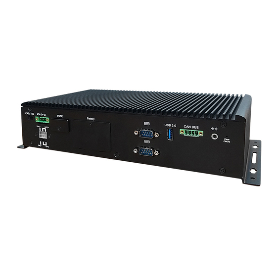
1.5 Product View Front View No. Name Name 1 Switch for Add‐on cards reset 8 VGA Connector 2 Line Input 9 2 x USB 3.1 (#1/$2) 3 Microphone Input A RJ45 for GbE 4 DSUB15 for DIDO B DSUB9 for COM1/COM2* 5 Micro SD card slot C DVI‐D Connector LED Indicators: Power (green), Storage (white), WLAN (blue), 6 WWAN (orange/option), D SSD Slot Warning of wrong voltage connected (red) Switch for power firmware load 7 System reset switch ... - Page 15 General Information Rear View No. Name Name 1 CAR/DC power mode switch 6 DSUB9 for COM3/4 RS232 Terminal block for power input 2 7 USB 3.0 port and IGN 22 ATX connector for external Terminal block for 2 masters 3 8 battery and 19VDC CANbus 4 Blade fuse socket with cover 9 Audio jack for line out 5 RTC battery access 0 Switch for clear CMOS MPT-1000V User’s Manual...
- Page 16 Oblique View MPT-2000V User’s Manual...
-
Page 17: Dimensions
General Information 1.6 Dimensions Unit: mm 1.7 Fuse Dimensions Littlefuse ® TAC ATO ® Style Blade 15A, 58V DC MPT-1000V User’s Manual... -
Page 18: Chapter 2 Hardware Configuration
Chapter 2 Hardware Configuration The information provided in this chapter includes: Essential installations before you begin Information and locations of connectors MPT-2000V User’s Manual... -
Page 19: Essential Installations
M.2 slot, there are a total of seven screws that need to be removed first. After doing the necessary installation, replacement or changes, put the screws back and tighten them. Please refer to the two pictures below for the location of the screws to be removed. MPT-1000V User’s Manual... -
Page 20: Memory Module Installation
2.1.1 Memory Module Installation The memory of the MPT-1000V is onboard type, there is no additional memory socket for expansion. MPT-1000V User’s Manual... -
Page 21: Ssd Storage Installation
Installing the SSD drive Release the two screws shown below and pull out the SSD tray. There are four screws that are to be loosen or tighten in the SSD drive during replacement as shown below. SSD/HDD Tray 4 screws MPT-1000V User’s Manual... -
Page 22: Sim And Micro-Sd Card Installation
Release the screw of the cover of the SIM/Micro-SD card slots. Insert the card(s) in their respective slots and push the card with your finger. Replace the cover when done. Or, to release the card(s), push the card again. MPT-1000V User’s Manual... -
Page 23: Mini-Pcie & M.2 Network Cards Installation
Insert the card slantwise. (Insert the M.2 network card in the same way.) 2. Push the mini-PCIe card down and hold it to the board with 2 flat head screws. (For the M.2 network card, use a round head screw.) MPT-1000V User’s Manual... -
Page 24: Wifi / 3G / 4G Antenna Installation
1. Thread and fasten the hex nut and the 2. Apply adhesive around here. washer. Then install the antenna. Info: The diameter of the nut is around 6.35 mm (0.25”-36UNC). Location of antenna holes MPT-1000V User’s Manual... -
Page 25: Mounting Brackets Installation
When mounting, ensure that you have enough room for power and signal cable routing. The method of mounting must be able to support weight of the MPT-1000V plus the suspend weight of all the cables to be attached to the system. -
Page 26: Setting The Jumpers
2.2 Setting the Jumpers Set up and configure your MPT-1000V by using jumpers for various settings and features according to your needs and applications. Contact your supplier if you have doubts about the best configuration for your use. 2.2.1 How to Set Jumpers Jumpers are short-length conductors consisting of several metal pins with a non-conductive base mounted on the circuit board. -
Page 27: Jumper & Connector Locations On Motherboard
Hardware Configuration 2.3 Jumper & Connector Locations on Motherboard Motherboard: MBT-1002 MBT-1002 – top view MPT-1000V User’s Manual... - Page 28 MBT-1002 – bottom view MPT-1000V User’s Manual...
-
Page 29: Jumpers Quick Reference
SW2: For DIO Verification use SW3: ATX Power ON Switch SW4: SIM Card Select J1: Pin header for SPI Debug SW5: Expansion Sockets Reset Button SW6: System Reset Button 2.4.1 BAT1: RTC Battery Pin Assigment Power Ground MPT-1000V User’s Manual... - Page 30 2.4.2 JP1: Clear ME Contents Function Pin closed Illustration Normal (default) Clear ME RTC Register 2.4.3 JP3: COM2 Terminator Enable Function Pin Setting Disabled Open Enabled Short/Closed (default) MPT-1000V User’s Manual...
- Page 31 Hardware Configuration 2.4.4 SW1: RTC Reset 2.4.5 SW2: For DIO Verification Used(Default off) Pin Assigment MPT-1000V User’s Manual...
- Page 32 2.4.6 SW3: ATX Power ON Switch 2.4.7 SW4: SIM Card Select Function Setting From M.2(Default) From Mini PCIe MPT-1000V User’s Manual...
- Page 33 Hardware Configuration 2.4.8 J1: Pin Header for SPI Debug 2.4.9 SW5: Expansion Sockets Reset Button MPT-1000V User’s Manual...
- Page 34 2.4.10 SW6: System Reset Button MPT-1000V User’s Manual...
-
Page 35: Connectors Quick Reference
J17: COM1 RS-232/422/485 Port J18: COM2 RS-485 Port LED1: Power LED LED2: SATA LED LED3: Blue Color LED for WLAN Activity Status LED4: Orange Color LED for WWAN Activity Status LED5: Firmware Programming LED LED6: Expansion Sockets Power Indicator MPT-1000V User’s Manual... - Page 36 2.5.1 CN1: USB 3.0 Port 2.5.2 CN2: Audio Line Out MPT-1000V User’s Manual...
- Page 37 Hardware Configuration 2.5.3 CN3, CN4: SATA Connectors 2.5.4 CN5: DVI-D Connector MPT-1000V User’s Manual...
- Page 38 2.5.5 CN6, CN7: GbE LAN Port (Intel WGI210IT) 2.5.6 CN8: Dual USB 3.0 Ports MPT-1000V User’s Manual...
- Page 39 Hardware Configuration 2.5.7 CN9: Dual Micro SIM Card Socket 2.5.8 CN10: Audio Mic In MPT-1000V User’s Manual...
- Page 40 2.5.9 CN11: Audio Line In 2.5.10 COM2 and DIDO Front Connectors Pin assignments for COM2 Pin Assigment Ground Pin assignments for DIDO Pin Assigment Pin Assigment MPT-1000V User’s Manual...
- Page 41 Hardware Configuration 2.5.11 CN12: Micro SD Slot 2.5.12 J2: Digital I/O Connector (Hirose DF11-20S-PA66H) Assigment Assigment VCC_COM GND_ISO_DIO GND_ISO_DIO GND_ISO_DIO GND_ISO_DIO GND_ISO_DIO GND_ISO_DIO GND_ISO_DIO MPT-1000V User’s Manual...
- Page 42 2.5.13 J3: CAN Bus Port (Dinkle ECH350RM-04P) Pin Assigment CAN_DH1 CAN_DL1 CAN_DH2 CAN_DL2 MPT-1000V User’s Manual...
- Page 43 Hardware Configuration 2.5.14 J4: COM3 RS-232 Port (HRS_DF11-10DP-2DSA) Pin Assigment Pin Assigment SOUT MPT-1000V User’s Manual...
- Page 44 2.5.15 J5: COM4 RS-232 Port (HRS_DF11-10DP-2DSA) Pin Assigment Pin Assigment SOUT MPT-1000V User’s Manual...
- Page 45 Hardware Configuration 2.5.16 J6: 19VDUAL Input Connector (ATX4PT-NY46) Pin Assigment Pin Assigment Ground Ground 19VDUAL 19VDUAL 2.5.17 J7: Connector to Power Board (Hirose DF3-8P-2DSA) Assigment Assigment SINF PWR_BTN# SOUTF POWER_OK VCC3_3 (2A) PS_ON# MPT-1000V User’s Manual...
- Page 46 2.5.18 J8: mPCIe Socket J8 supports PCIe, USB 2.0 + SMBus + mSATA. 2.5.19 J9: 80 Port MPT-1000V User’s Manual...
- Page 47 Hardware Configuration 2.5.20 J10: mPCIe Socket J10 supports PCIe, USB 2.0+ SMBus + SIM card. 2.5.21 J11, J12: SATA Power Connectors (JST B4B-XH-A) Pin Assigment VCC5 (1A) VCC12 (1A) MPT-1000V User’s Manual...
- Page 48 J13: M.2 Type 3042 (B Key) Socket J13 is for USB3.0 +USB 2.0 and 2 SIM cards. For pin definition, refer to Sierra EM7455 and EM7565. 2.5.23 J14: USB 2.0 Connector (Hirose DF11-8S-PA66H) Pin Assigment Pin Assigment VCC (0.5A) VCC (0.5A) MPT-1000V User’s Manual...
- Page 49 Hardware Configuration 2.5.24 J15: USB 2.0 Connector (JST B4B-PH-K-S) Pin Assigment VCC (0.5A) MPT-1000V User’s Manual...
- Page 50 2.5.25 J16: VGA Connector (Hirose DF11-16DP-2DSA) Pin Assigment Pin Assigment NONE NONE DDC_DATA HSYNC VSYNC DDC_CLK NONE MPT-1000V User’s Manual...
- Page 51 Hardware Configuration 2.5.26 J17: COM1 RS-232/422/485 Port (Hirose DF11-10DP-2DSA) J17 COM1 port is jumper-less and configurable in the BIOS. Signal Name RS-232 RS-422 RS-485 Data- Data+ Ground Ground Ground MPT-1000V User’s Manual...
- Page 52 2.5.28 LED1: Power LED 2.5.29 LED2: SATA LED 2.5.30 LED3: Blue Color LED for WLAN Activity Status 2.5.31 LED4: Orange Color LED for WWAN Activity Status 2.5.32 LED5: Firmware Programming LED 2.5.33 LED6: Expansion Sockets Power Indicator MPT-1000V User’s Manual...
-
Page 53: Chapter 3 Drivers Installation
Chapter 3 Drivers Installation The information provided in this chapter includes: Intel ® Chipset Software Installation Utility VGA Driver Installation HD Audio Driver Installation LAN Driver Installation ® Intel Trusted Execution Engine Installation Intel ® Serial I/O Driver Installation ... -
Page 54: Introduction
INF files for Plug & Play function for the chipset components. Follow the instructions below to complete the installation. Insert the drivers disk enclosed in the system package. In the initial screen, click Intel and then Intel(R) Apollolake Chipset Drivers. Click Intel(R) Chipset Software Installation Utility. MPT-1000V User’s Manual... - Page 55 Drivers Installation ® When the Welcome screen to the Intel Chipset Device Software appears, click Next to continue. Click Yes to accept the software license agreement. MPT-1000V User’s Manual...
- Page 56 After reading the Readme File information, click Install. Click Finish to complete the setup process. MPT-1000V User’s Manual...
-
Page 57: Vga Driver Installation
In the Readme File Information screen, click Next. In the Setup Progress screen, click Next. When Setup is Complete, restart the system for the changes to take effect. Click Finish. MPT-1000V User’s Manual... -
Page 58: Hd Audio Driver Installation
3.4 HD Audio Driver Installation In the initial screen, click Intel and then Intel(R) Apollolake Chipset Drivers. Click Realtek High Definition Audio Driver. MPT-1000V User’s Manual... - Page 59 Drivers Installation On the Welcome to the InstallShield Wizard screen, click Next. Click Finish to complete setup. MPT-1000V User’s Manual...
-
Page 60: Lan Driver Installation
3.5 LAN Driver Installation Click Intel LAN Controller Drivers. Click Intel(R) Gigabit Ethernet Drivers. In the Welcome screen, click Next. MPT-1000V User’s Manual... - Page 61 Drivers Installation Accept the terms of the license agreement and click Next. In the Setup Options screen, click Next. In Ready to Install the Program screen, click Install. In the Install wizard Completed screen, click Finish. MPT-1000V User’s Manual...
-
Page 62: Intel Trusted Execution Engine Installation
® 3.6 Intel Trusted Execution Engine Installation In the initial screen, click Intel and then Intel(R) Apollolake Chipset Drivers. Click Intel(R) TXE Drivers. When the Welcome screen appears, click Next. MPT-1000V User’s Manual... - Page 63 Drivers Installation Click Next to accept the terms in the license agreement. In the Confirmation screen, click Next. When installation is complete, click Finish. MPT-1000V User’s Manual...
-
Page 64: Intel Serial I/O Drivers Installation
When the Weocome screen appears, click Next to contiune installation. Click Next to accept the terms in the license agreement. In the Readme File Information screen, click Next. In the Confirmation screen, click Next. Restart the system for the changes to take effect. Click Finish. MPT-1000V User’s Manual... -
Page 65: Chapter 4 Bios Setup
Chapter 4 BIOS Setup This chapter the different settings available in the AMI describes BIOS that comes with the board. The topics covered in this chapter are as follows: Main Settings Advanced Settings Chipset Settings Security Settings ... -
Page 66: Introduction
These defaults have been carefully chosen by both AMI and your system manufacturer to provide the absolute maximum performance and reliability. Changing the defaults could make the system unstable and crash in some cases. MPT-1000V User’s Manual... -
Page 67: Main Settings
BIOS Setup 4.3 Main Settings BIOS Setting Description System Date Sets the date. Use the <Tab> key to switch between the data elements. System Time Set the time. Use the <Tab> key to switch between the data elements. MPT-1000V User’s Manual... -
Page 68: Advanced Settings
4.4 Advanced Settings This section allows you to configure, improve your system and allows you to set up some system features according to your preference. BIOS Setting Description ACPI Settings System ACPI Parameters. MPT-1000V User’s Manual... - Page 69 BIOS Setup 4.4.1 ACPI Settings BIOS Setting Description Enable Hibernation Enables or disables the System ability to Hibernate (OS/S4 Sleep State). This option may not be effective with some OS. MPT-1000V User’s Manual...
- Page 70 4.4.2 Super I/O Configuration BIOS Setting Description Serial Port 1~4 Configuration Set Parameters of Serial Port Serial Port 1 Configuration MPT-1000V User’s Manual...
- Page 71 BIOS Setup Serial Port 2 Configuration Serial Port 3 Configuration Serial Port 4 Configuration MPT-1000V User’s Manual...
- Page 72 Hardware Monitor BIOS Setting Description Temperatures / Voltages These fields are the parameters of the hardware monitoring function feature of the motherboard. The values are read-only values as monitored by the system and show the PC health status MPT-1000V User’s Manual...
- Page 73 Socket 0 CPU Information Displays the socket specific CPU Information. Turbo Mode Options: Disabled, Enabled Active Processor Cores Number of cores to enable in each processor package Options: Disabled, Enabled Monitor Mwait Enable/Disable Monitor Mwait Options: Disabled, Enabled, Auto MPT-1000V User’s Manual...
- Page 74 Hub descriptor. Generic Ultra Mass storage device emulation type. “AUTO’ MS-COMBO enumerates devices according to their media format. Optical drives are emulated as ‘CDROM’ drives with no media will be emulated according to a drive type. MPT-1000V User’s Manual...
- Page 75 BIOS Setup 4.4.6 CSM Configuration 4.4.7 Power Configuration MPT-1000V User’s Manual...
-
Page 76: Chipset Settings
PCI Express Active State Power Management settings Options: Disable, L0s, L1, L0sL1, Auto L1 Substates PCI Express L1 Substates settings Options: L1.1, L1.2, L1.2 & L1.2 PME SCI PCI Express PME SCI Enable/Disable PCIe Speed Configure PCIe Speed Options: Auto, Gen1, Gen2 MPT-1000V User’s Manual... - Page 77 USB port from reporting a Device Connection to the controller. XDCI Support Options: Enable, Disable XHCI Didable Options to disable XHCI Link Compliance Compliance Mode Mode. Default is FALSE to not disable Compliance Mode. Set TRUE to disable Compliance Mode. MPT-1000V User’s Manual...
-
Page 78: Security Settings
Sets an administrator password for the setup utility. User Password Sets a user password. Secure Boot feature is active if Secure Boot is enabled. Platform Key(PK) is enrolled and the Secure Boot system is in user mode. The mode change requires platform reset. MPT-1000V User’s Manual... - Page 79 Force System to User Mode. Install factory default Secure Boot key databases. Delete all Secure Boot key databases from Reset To Setup Mode NVRAM Provision factory default keys on next re-boot Factory Key Provision only when System in Setup Mode. MPT-1000V User’s Manual...
-
Page 80: Boot Settings
Has no effect for BBS boot options. Boot Option Priorities Sets the system boot order. UEFI Hard Disk Drive Specifies the Boot Device Priority sequence from BBS Priorities available UEFI Hard Disk Drives. MPT-1000V User’s Manual... -
Page 81: Save & Exit Settings
Restore Defaults Restores / Loads defaults values for all the setup options. Save as User Defaults Saves the changes done so far as user defaults. Restore User Defaults Restores the user defaults to all the setup options. MPT-1000V User’s Manual... -
Page 82: Appendix
Appendix This section provides the mapping addresses of peripheral devices and the sample code of watchdog timer configuration. I/O Port Address Map Interrupt Request Lines (IRQ) Watchdog Timer Configuration Software Development Kit for WDT.DLL... -
Page 83: I/O Port Address Map
Motherboard resources 0x00000600-0x0000061F Motherboard resources 0x0000164E-0x0000164F Motherboard resources 0x0000E000-0x0000EFFF PCI-to-PCI Bridge 0x000003F8-0x000003FF Communications Port (COM1) 0x000002F8-0x000002FF Communications Port (COM2) 0x000003E8-0x000003EF Communications Port (COM3) 0x000002E8-0x000002EF Communications Port (COM4) 0x000002E0-0x000002E7 Communications Port (COM5) 0x0000C000-0x0000CFFF PCI-to-PCI Bridge 0x00000020-0x00000021 Programmable interrupt controller MPT-1000V User’s Manual... - Page 84 Standard SATA AHCI Controller 0x00000000-0x0000006F PCI Express Root Complex 0x00000078-0x00000CF7 PCI Express Root Complex 0x00000D00-0x0000FFFF PCI Express Root Complex 0x0000F040-0x0000F05F SM Bus Controller 0x0000D000-0x0000DFFF PCI-to-PCI Bridge 0x0000F000-0x0000F03F Microsoft Basic Display Adapter 0x00000040-0x00000043 System timer 0x00000050-0x00000053 System timer MPT-1000V User’s Manual...
-
Page 85: Interrupt Request Lines (Irq)
High Definition Audio Controller IRQ 14 Intel(R) Serial IO GPIO Host Controller - INT3452 IRQ 27 Intel(R) Serial IO I2C Host Controller - 5AAC Intel(R) USB 3.0 eXtensible Host Controller - 1.0 IRQ 4294967281 (Microsoft) IRQ 0 System timer MPT-1000V User’s Manual... -
Page 86: Watchdog Timer Configuration
Fintek 81866, program abort.\n"); return(1); }//if (SIO == 0) if (argc != 2) printf(" Parameter incorrect!!\n"); return (1); bTime = strtol (argv[1], endptr, 10); printf("System will reset after %d seconds\n", bTime); if (bTime) EnableWDT(bTime); } else DisableWDT(); } return 0; MPT-1000V User’s Manual... - Page 87 //--------------------------------------------------------------------------- void DisableWDT(void) unsigned char bBuf; Set_F81866_LD(0x07); //switch to logic device 7 bBuf = Get_F81866_Reg(0xFA); bBuf &= ~0x01; Set_F81866_Reg(0xFA, bBuf); //disable WDTO output bBuf = Get_F81866_Reg(0xF5); bBuf &= ~0x20; bBuf |= 0x40; Set_F81866_Reg(0xF5, bBuf); //disable WDT //--------------------------------------------------------------------------- MPT-1000V User’s Manual...
- Page 88 Init_Finish; } F81866_BASE = 0x00; result = F81866_BASE; Init_Finish: return (result); //--------------------------------------------------------------------------- void Unlock_F81866 (void) outportb(F81866_INDEX_PORT, F81866_UNLOCK); outportb(F81866_INDEX_PORT, F81866_UNLOCK); //--------------------------------------------------------------------------- void Lock_F81866 (void) outportb(F81866_INDEX_PORT, F81866_LOCK); //--------------------------------------------------------------------------- void Set_F81866_LD( unsigned char LD) Unlock_F81866(); outportb(F81866_INDEX_PORT, F81866_REG_LD); outportb(F81866_DATA_PORT, LD); Lock_F81866(); MPT-1000V User’s Manual...
- Page 89 //--------------------------------------------------------------------------- #defineF81866_INDEX_PORT (F81866_BASE) #defineF81866_DATA_PORT (F81866_BASE+1) //--------------------------------------------------------------------------- #defineF81866_REG_LD 0x07 //--------------------------------------------------------------------------- #define F81866_UNLOCK 0x87 #defineF81866_LOCK 0xAA //--------------------------------------------------------------------------- unsigned int Init_F81866(void); void Set_F81866_LD( unsigned char); void Set_F81866_Reg( unsigned char, unsigned char); unsigned char Get_F81866_Reg( unsigned char); //--------------------------------------------------------------------------- #endif // F81866_H MPT-1000V User’s Manual...
-
Page 90: Software Development Kit For Wdt.dll
Installation For 32-bit environment: Step 1: Copy the file KMUI32_1K.SYS to <%WINDIR%>\SYSTEM32\DRIVERS. Step 2: The following parameters must be written to your registry. HKLM,"System\CurrentControlSet\Services\KMUI32_1K","ErrorContr ol",%REG_DWORD%,0x00000001 HKLM,"System\CurrentControlSet\Services\ KMUI32_1K","Type",%REG_DWORD%,0x00000001 HKLM,"System\CurrentControlSet\Services\ KMUI32_1K","Start",%REG_DWORD%,0x00000000 HKLM,"System\CurrentControlSet\Services\ KMUI32_1K","DisplayName",%REG_SZ%,"KMUI32_1K" Step 3: Restart the system. MPT-1000V User’s Manual... - Page 91 The following parameters must be written to your registry. HKLM,"System\CurrentControlSet\Services\KMUI64_1K","ErrorControl",%R EG_DWORD%,0x00000001 HKLM,"System\CurrentControlSet\Services\ KMUI64_1K","Type",%REG_DWORD%,0x00000001 HKLM,"System\CurrentControlSet\Services\ KMUI64_1K","Start",%REG_DWORD%,0x00000000 HKLM,"System\CurrentControlSet\Services\ KMUI64_1K","DisplayName",%REG_SZ%,"KMUI64_1K" Step 3: Restart the system. Note: Do not install both of the 32-bit and 64-bit drivers on an operating system. MPT-1000V User’s Manual...
- Page 92 Output : Always return 1. Note: This function should be invoked before the program closes and it will release the device driver and memory for ib_wdt.dll. If the program is closed without calling this routine, resource leak may occur. MPT-1000V User’s Manual...
- Page 93 Output : Always return “0” For further information, refer to the datasheet for WDT or contact your sales representative. extern "C" __declspec(dllexport) int __stdcall DisableWDT(int); Input : Dummy data and will be ignored. Output : Always return “0” MPT-1000V User’s Manual...
- Page 94 GPIO_6 are the output functions. Output : Dummy data and should be ignored. extern "C" __declspec(dllexport) int __stdcall SetDioOutputMask(int); Input : Hardware parameter for digital I/O output function call For further information, refer to the following explanation of “SetDioInputMask” routine. MPT-1000V User’s Manual...
- Page 95 Set GPIO_5 to GPIO_6 to HIGH\n"); Sleep(500); if (_kbhit()) break; }//if (kbhit()) }//while(1) }//if ((*lpIsDioAvailable)(0)) Note: Be sure to set up the input / output for GPIO bits in BIOS identically with the GPIO hardware information above. MPT-1000V User’s Manual...
-
Page 96: Motherboard Mcu Isp Specifications
THL max setting value, MCU trigger THL delay timer. Setting THL Low Temperature MCU provides command to set low temperature protection, when system temperature is lower than THL low setting value, MCU trigger THL delay timer. MPT-1000V User’s Manual... - Page 97 MCU provides command to set temperature offset. It can adjust temperature disparity between system and power board. Setting CB Voltage Offset MCU provides command to set car battery voltage offset. It can adjust this voltage disparity between actual measurement and detected form MCU. MPT-1000V User’s Manual...
- Page 98 Note: Before using the ISP, your software engineer has to make sure the firmware version (GET_FORMWARE_VERSION) MUST be as follows to make the ISP function workable. Major version is 0. Minor version is 0. Build version is 5 (or above). MPT-1000V User’s Manual...
- Page 99 Protocol uses 16-bit CCITT CRC to verify data integrity. P(x) = X unsigned calc_crc(unsigned char *data, unsigned unsigned start) { unsigned I, k, q, c, crcval; crcval=start; (I=0; I<n; I++) { c=data(I) & 0xFF; q=(crcval^c) & 0x0F; crcval=(crcval>>4)^(q*0x1081); q=(crcval^(c>>4)) & 0x0F; crcval=(crcval>>4)^(q*0x1081); return crcval; MPT-1000V User’s Manual...
- Page 100 CB(car battery) SET_PB_UVP 0xB1 Setting Low voltage protect for PB(ups battery) SET_CB_POWRE_GOOD 0xB2 Setting CB (car battery) good voltage SET_PB_POWRE_GOOD 0xB3 Setting PB (ups battery) good voltage GET_CURRENT_CB_PB_VOLTAGE 0xB4 Get current voltage for CB & PB MPT-1000V User’s Manual...
- Page 101 BSL Version Structure Field Type Description Major Version Byte Major version number (0x00) Minor Version Byte Minor version number (0x00) Build Byte Build version number (0x05) Note: In this spec, MCU’s build version must be 0x05. MPT-1000V User’s Manual...
- Page 102 Setting Power-Off Delay Timer Parameter: SET_POWER_OFF_DELAY_TIMER Sets power off delay timer. Request: Header Size Command Data0 Data1 0xFF 0x02 SET_POWER_OFF_DELAY_TIMER 0xEE (mins) (secs) Reply Header Size Command Data 0xFF 0x00 SET_POWER_OFF_DELAY_TIMER None 0xEE Note: Data1 range must be MPT-1000V User’s Manual...
- Page 103 Setting Low Delay Timer Parameter: SET_LOW_ DELAY_TIMER Sets low delay timer. Request: Header Size Command Data0 Data1 0xFF 0x02 SET_LOW_DELAY_TIMER 0xEE (mins) (secs) Reply Header Size Command Data 0xFF 0x00 SET_LOW_DELAY_TIMER None 0xEE Note: Data1 range must be MPT-1000V User’s Manual...
- Page 104 Setting THL Max Parameter: SET_THL_ MAX_TEMPERATURE_VALUE Sets max. temperature protection. Request: Header Size Command Data 0xFF 0x01 SET_THL_MAX 0xEE (degree) Reply Header Size Command Data 0xFF 0x00 SET_THL_MAX None 0xEE Note: Data range must be +85~ (-50). MPT-1000V User’s Manual...
- Page 105 0xEE Note: Data range must be +85~ (-50). Getting THL Now Parameter: GET_THL_ NOW Gets the current temperature. Request: Header Size Command 0xFF 0x00 SET_THL_MOW 0xEE Reply Header Size Command Data 0xFF 0x01 SET_THL_NOW 0xEE (degree) MPT-1000V User’s Manual...
- Page 106 Reply Header Size Command Data 0xFF 0x00 SET_PB_UVP None 0xEE Round off to the 1 decimal place. Ex. Setting 11.2V mapping to 11200 (11.2 x 1000) = 2BC0 (hex) Data0 = 2B (hex) Data1 = C0 (hex) MPT-1000V User’s Manual...
- Page 107 Reply Header Size Command Data 0xFF 0x00 SET_PB_GOOD None 0xEE Round off to the 1 decimal place. Ex. Setting 11.2V mapping to 11200 (11.2 x 1000) = 2BC0 (hex) Data0 = 2B (hex) Data1 = C0 (hex) MPT-1000V User’s Manual...
- Page 108 Reply Header Size Command Data 0xFF 0x00 SET_CHG_STV None 0xEE Round off to the 1 decimal place. Ex. Setting 13.2V mapping to 13200 (13.2 x 1000) = 3390 (hex) Data0 = 33 (hex) Data1 = 90 (hex) MPT-1000V User’s Manual...
- Page 109 Sets offset to adjust temperature difference between system and power board. Request: Header Size Command Data 0xFF 0x01 SET_THL_OFFSET 0xEE (degree) Reply Header Size Command Data 0xFF 0x00 SET_THL_OFFSET None 0xEE Note: Data range must be +40~ (-40). MPT-1000V User’s Manual...
- Page 110 Sets offset to adjust PB voltage difference between actual measurement and detected form MCU. Request: Header Size Command Data 0xFF 0x01 SET_PB_OFFSET 0xEE Reply Header Size Command Data 0xFF 0x00 SET_PB_OFFSET None 0xEE Note: Data range must be +5V~ (-5V). MPT-1000V User’s Manual...
- Page 111 Byte19 + Byte20 CHG stv Word Byte21 + Byte22 CHG spv Word Byte23 + Byte24 CB NOW Word Byte25 + Byte26 PB NOW Word Byte27 + Byte28 THL offset Byte Byte29 CB offset Byte Byte30 PB offset Byte Byte31 MPT-1000V User’s Manual...
Need help?
Do you have a question about the MPT-1000V and is the answer not in the manual?
Questions and answers