Table of Contents
Advertisement
Quick Links
Advertisement
Table of Contents

Subscribe to Our Youtube Channel
Related Manuals for IBASE Technology SI-64 Series


Summary of Contents for IBASE Technology SI-64 Series
- Page 1 SI-64 Series User Manual IBASE Technology Inc.
- Page 2 SI-64 User Manual Revision Release Date V0.1 2013/11/05 V0.2 2014/03/10 V0.3 2015/01/06 Copyright © 2013 IBASE Technology Inc. All Rights Reserved.
- Page 3 SI-64 User Manual Copyright © 2013 IBASE Technology Inc. All Rights Reserved. No part of this manual, including the products and software described in it, may be reproduced, transmitted, transcribed, stored in a retrieval system, or translated into any language in any form or by any means, except documentation kept by the purchaser for backup purposes, without the express written permission of IBASE Technology INC.
-
Page 4: Table Of Contents
SI-64 User Manual Table of Contents Setting up your system ......................3 Care during use ........................4 Acknowledgments ....................... 4 CHAPTER 1 INTRODUCTION ..................6 1.1 General Description ....................... 6 1.2 System Specifications..................... 6 1.2.2 Dimensions ......................... 7 1.2.3 I/O View ........................8 1.3 Exploded View of the SI-64 Assembly ................ -
Page 5: Setting Up Your System
SI-64 User Manual Safety Information Your SI-64 is designed and tested to meet the latest standards of safety for information technology equipment. However, to ensure your safety, it is important that you read the following safety instructions Setting up your system ... -
Page 6: Care During Use
SI-64 User Manual Care during use Do not walk on the power cord or allow anything to rest on it. Do not spill water or any other liquids on your system. When the system is turned off, a small amount of electrical current still flows. Always unplug all power, and network cables from the power outlets before cleaning the system. -
Page 7: Acknowledgments
FINTEK is a registered trademark of FINTEK Electronics Corporation. REALTEK is a registered trademark of REALTEK Electronics Corporation. All other product names or trademarks are properties of their respective owners. Copyright © 2013 IBASE Technology Inc. All Rights Reserved. -
Page 8: Chapter 1 Introduction
SI-64 User Manual CHAPTER 1 INTRODUCTION 1.1 General Description SI-64 comes with the Intel® Q77 Express Chipset and Radeon E6760 embedded discrete graphics processor that enables outstanding graphics experience and up to four DVI outputs using AMD Eyefinity Technology for video wall application. 1.2 System Specifications 1.2.1 Hardware Specifications Model Name... -
Page 9: Dimensions
Relative Humidity 5~90% @45°C (non-condensing) Vibration mSATA: 5 Grms/5~500Hz random operation RoHS Certification CE, FCC class B, CCC and UL ‧ This specification is subject to change without prior notice. 1.2.2 Dimensions Copyright © 2013 IBASE Technology Inc. All Rights Reserved. -
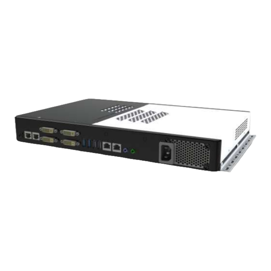
Page 10: I/O View
SI-64 User Manual 1.2.3 I/O View Item Connector Item Connector Power button 4x USB ports Power/HDD LED Indicator 2x RJ45 for LAN 2x RJ45 for RS-232 Line-in/Line-out 3x DVI, 1 x Hybrid DVI AC Inlet... -
Page 11: Exploded View Of The Si-64 Assembly
1.3 Exploded View of the SI-64 Assembly 1.3.1 Parts Description Part No. Description Part No. Description SI-64 Base IB964 motherboard Power module SI-64 side bracket SI-64 fix bracket SI-64 L-cover SI-64 R-cover Copyright © 2013 IBASE Technology Inc. All Rights Reserved. -
Page 12: Packing List
SI-64 User Manual 1.4 Packing List Item No. Description Driver CD Screw; B30 Wall Mount Kits Power Cord 1.4.1 Optional Items Description WiFi Solution QCOM WiFi Wireless LAN Card; 802.11 B/G/N+BT HALF Card module [Q802XKN3B] RoHS (A008WIRELESS00700P) External Antenna Wifi Antenna (A055RFA02C2M20800P) From Wifi module to Rear/Front panel Internal cable-1/2 (A055RFA0000021000P/A055RFA0000032000P) -
Page 13: Hardware Installation
2. Gently push the DDR3 module in an upright position until the clips of the slot close to hold the DDR3 module in place when the DDR3 module touches the bottom of the slot. 3. To remove the DDR3 module, press the clips with both hands. Copyright © 2013 IBASE Technology Inc. All Rights Reserved. -
Page 14: Installing The Hdd/Msata Module
SI-64 User Manual 2.3 Installing the HDD/mSATA Module HDD Module: 1. Remove the two screws on the sides that are used to secure the black top cover to the chassis. Once all the screws are removed, from the side, push the cover forward to remove it. - Page 15 IBASE Technology Inc. 3. Following the picture’s arrowed direction, push out the HDD module. 4. Loosen the four screws and then replace the HDD module. Copyright © 2013 IBASE Technology Inc. All Rights Reserved.
- Page 16 SI-64 User Manual mSATA Module: 1. Remove the two screws on the sides that are used to secure the white top cover to the chassis. Once all the screws are removed, from the side, push the cover forward to remove it. See steps1 and 2 in the picture. 2.
-
Page 17: Installing The Wireless Module
Once all the screws are removed, from the side, push the cover forward to remove it. See steps1 and 2 as in the picture. 2. Push the WIFI module into the slot. Screw one screw to secure the module to the slot. Copyright © 2013 IBASE Technology Inc. All Rights Reserved. -
Page 18: Chapter 3 Motherboard Introduction
SI-64 User Manual CHAPTER 3 MOTHERBOARD INTRODUCTION 3.1 Introduction The IB964 ATX motherboard is based on the latest Intel Q77 chipset. The platform supports 3 generation Intel Core processor family with LGA1155 packing and features an integrated dual-channel DDR3 memory controller as well as a graphics core. - Page 19 LAN Wakeup Dimensions 305mm x 243mm Power Supply Power 250W PSU Environmental Temperature Operating: -10°C~60°C Humidity 10%~90% (non-condensing) Shock IBASE Standard Test Vibration IBASE Standard Test Certification RoHS Other CE/FCC Class B Copyright © 2013 IBASE Technology Inc. All Rights Reserved.
-
Page 20: Board Dimensions
SI-64 User Manual Board Dimensions... -
Page 21: Setting The Jumpers
Contact your supplier if you have doubts about the best configuration for your needs. The following lists the connectors on IB964 and their respective functions. Jumper Locations on IB964 Copyright © 2013 IBASE Technology Inc. All Rights Reserved. - Page 22 SI-64 User Manual JBAT1: Clear CMOS Contents JBAT1 Setting Function Pin 1-2 Normal Short/Closed Pin 2-3 Clear CMOS Short/Closed JP3: Flash Descriptor Security Override (Factory use only) Flash Descriptor Security Override Disabled Open (Default) Close Enabled...
- Page 23 JP8: COM1 RS232 RI/+5V/+12V Power Setting Setting Function Pin 1-3 +12V Short/Closed Pin 3-4 Short/Closed Pin 3-5 Short/Closed JP9: COM2 RS232 RI/+5V/+12V Power Setting Setting Function Pin 1-3 +12V Short/Closed Pin 3-4 Short/Closed Pin 3-5 Short/Closed Copyright © 2013 IBASE Technology Inc. All Rights Reserved.
-
Page 24: Connectors On Ib964
SI-64 User Manual 3.3 Connectors on IB964... - Page 25 DDC DATA SHIELD CLK VSYNC CLOCK - DATA 1- CLOCK + DATA 1+ SHIELD 1/3 Green DATA 3- Blue DATA 3+ HSYNC DDC POWER A GROUND2 A GROUND 1 A GROUND3 Copyright © 2013 IBASE Technology Inc. All Rights Reserved.
- Page 26 SI-64 User Manual Signal Name Pin # Pin # Signal Name DATA 2- HOT POWER DATA 2+ DATA 0- Shield 2/4 DATA 0+ DATA 4- SHIELD 0/5 DATA 4+ DATA 5- DDC CLOCK DATA 5+ DDC DATA SHIELD CLK CLOCK - DATA 1- CLOCK + DATA 1+...
- Page 27 This connector supplies the CPU operating voltage. Pin # Signal Name Ground Ground +12V +12V J6, J10: USB Connectors Signal Name Pin # Pin # Signal Name J11: Mini-PCIE Connector J12: Mini-PCIE Connector and mSATA/share with SATA3.0 Copyright © 2013 IBASE Technology Inc. All Rights Reserved.
- Page 28 SI-64 User Manual J14: Digital I/O Signal Name Signal Name Pin# Pin# OUT3 OUT1 OUT2 OUT0 J19, J20: COM3, COM4 RS232 Serial Ports Signal Name Pin # Pin # Signal Name DCD# DSR# SIN# RTS# SOUT CTS# DTR# JP4: LPC debug Connector (Factory use only) CPU_FAN1: CPU Fan Power Connector Pin # Signal Name...
- Page 29 IBASE Technology Inc. SYS_FAN1: System Fan1 Power Connector Pin # Signal Name Ground +12V Rotation detection SYS_FAN2: System Fan2 Power Connector Pin # Signal Name Ground +12V Copyright © 2013 IBASE Technology Inc. All Rights Reserved.
-
Page 30: Chapter 4 Bios Setup
SI-64 User Manual CHAPTER 4 BIOS SETUP This chapter describes the different settings available in the AMI BIOS that comes with the board. The topics covered in this chapter are as follows: BIOS Introduction The BIOS (Basic Input/Output System) installed in your computer system’s ROM supports Intel processors. - Page 31 ► Acoustic Management Configuration +- Change Field ► USB Configuration F1:General Help ► F81866 Super IO Configuration F2:Previous Values ► F81866 H/W Monitor F3: Optimized Default ► CPU PPM Configuration F4: Save ESC: Exit Copyright © 2013 IBASE Technology Inc. All Rights Reserved.
- Page 32 SI-64 User Manual PCI Subsystem Settings Aptio Setup Utility Advanced Main Chipset Boot Security Save & Exit PCI Bus Driver Version V 2.0502 PCI 64bit Resources Handing Above 4G Decoding Disabled → ← Select Screen PCI Common Settings ↑↓ Select Item PCI Latency Timer 32 PCI Bus Clocks Enter: Select...
- Page 33 Set the ASPM Level: Force L0s – Force all links to L0s State: AUTO – BIOS auto configure: DISABLE – Disables ASPM. Extended Synch If ENABLED allows generation of Extended Synchronization patterns. Copyright © 2013 IBASE Technology Inc. All Rights Reserved.
- Page 34 SI-64 User Manual Link Training Retry Defines number of Retry Attempts software will take to retrain the link if previous training attempt was unsuccessful. Link Training Timeout (uS) Defines number of Microseconds software will wait before polling ‘Link Training’ bit in Link Status register.
- Page 35 TPM. Reset of platform is required. Security Device Support Enables or disables BIOS support for security device. O.S. will not show Security Device. TCG EFI protocol and INT1A interface will not be available. Copyright © 2013 IBASE Technology Inc. All Rights Reserved.
- Page 36 SI-64 User Manual CPU Configuration This section shows the CPU configuration parameters. Aptio Setup Utility Main Advanced Chipset Boot Security Save & Exit CPU Configuration Intel® Core ™ i7-3770 CPU @ 3.40GHz Processor Stepping 306a8 Microcode Revision Max CPU Speed 3400 MHz Min CPU Speed 1600 MHz...
- Page 37 Empty F3: Optimized Default Software Preserve Unknown F4: Save ESC: Exit SATA Controller(s) Enable / Disable Serial ATA Controller. SATA Mode Selection (1) IDE Mode. (2) AHCI Mode. (3) RAID Mode. Copyright © 2013 IBASE Technology Inc. All Rights Reserved.
- Page 38 SI-64 User Manual Shutdown Temperature Configuration Aptio Setup Utility Main Advanced Chipset Boot Security Save & Exit → ← Select Screen APCI Shutdown Temperature Disabled ↑↓ Select Item Enter: Select +- Change Field F1:General Help F2:Previous Values F3: Optimized Default F4: Save ESC: Exit ACPI Shutdown Temperature The default setting is Disabled.
- Page 39 Note: iAMT H/W is always enabled. This option just controls the BIOS extension execution. If enabled, this requires additional firmware in the SPI device. Unconfigure ME This configuration is supported only with IB964VF (with iAMT function). Perform AMT/ME unconfigure without password operation. Copyright © 2013 IBASE Technology Inc. All Rights Reserved.
- Page 40 SI-64 User Manual AMT Wait Timer Set timer to wait before sending ASF_GET_BOOT_OPTIONS. Activate Remote Assistance Process Trigger CIRA boot. PET Progress User can Enable/Disable PET Events progress to receive PET events or not. Watchdog Timer This configuration is supported only with IB964VF (with iAMT function). Enable/Disable Watchdog Timer.
- Page 41 Maximum time the device will take before it properly reports itself to the Host Controller. ‘Auto’ uses default value: for a Root port it is 100ms, for a Hub port the delay is taken from Hub descriptor. Copyright © 2013 IBASE Technology Inc. All Rights Reserved.
- Page 42 SI-64 User Manual F81866 Super IO Configuration Aptio Setup Utility Main Advanced Chipset Boot Security Save & Exit Super IO Configuration F81866 Super IO Chip F81866 ► Serial Port 0 Configuration ► Serial Port 1 Configuration → ← Select Screen ►...
- Page 43 Fan1/Fan2 Smart Fan Control This field enables or disables the smart fan feature. At a certain temperature, the fan starts turning. Once the temperature drops to a certain level, it stops turning again. Copyright © 2013 IBASE Technology Inc. All Rights Reserved.
- Page 44 SI-64 User Manual CPU PPM Configuration Aptio Setup Utility Main Advanced Chipset Boot Security Save & Exit CPU PPM Configuration → ← Select Screen EIST Enabled ↑↓Select Item Turbo Mode Enabled Enter: Select +- Change Field F1: General Help F2: Previous Values F3: Optimized Default F4: Save ESC: Exit EIST...
- Page 45 ME is on at Sx state.) SLP_S4 Assertion Width Select a minimum assertion width of the SLP_S4# signal. Restore AC Power Loss Select AC power state when power is re-applied after a power failure. Copyright © 2013 IBASE Technology Inc. All Rights Reserved.
- Page 46 SI-64 User Manual PCI Express Configuration Main Advanced Chipset Boot Security Save & Exit PCI Express Configuration PCI Express Clock Gating Enabled DMI Link ASPM Control Enabled DMI Link Extended Synch Control Disabled PCIe-USB Glitch W/A Disabled Subtractive Decode Disabled ►...
- Page 47 Azalia Auto Azalia Control Detection of the Azalia device. Disabled = Azalia will unconditionally disabled. Enabled Azalia will be unconditionally enabled. Auto = Azalia will be enabled if present, disabled otherwise. Copyright © 2013 IBASE Technology Inc. All Rights Reserved.
- Page 48 SI-64 User Manual System Agent (SA) Configuration Aptio Setup Utility Main Advanced Chipset Boot Security Save & Exit System Agent Bridge Name IvyBridge System Agent RC Version 1.1.0.0 VT-d Capability Supported VT-d Enabled CHAP Device (B0:D7:F0) Disabled Thermal Device (B0:D4:F0) Disabled →...
- Page 49 Select the Video Device that will be activated during POST. This has no effect if external graphics present. Secondary booty display selection will appear based on your selection. VGA modes will be supported only on primary display. Copyright © 2013 IBASE Technology Inc. All Rights Reserved.
- Page 50 SI-64 User Manual Memory Configuration Aptio Setup Utility Main Advanced Chipset Boot Security Save & Exit Memory Information Memory Frequency 1333 MHz Total Memory 8192 MB (DDR3) DIMM#0 2048 MB (DDR3) DIMM#1 2048 MB (DDR3) DIMM#2 2048 MB (DDR3) → ← Select Screen DIMM#3 2048 MB (DDR3) ↑↓Select Item...
- Page 51 Set display mode for Option ROM. Options are Force BIOS and Keep Current. INT19 Trap Response Enable: Allows Option ROMs to trap Int 19. Boot Option Priorities Sets the system boot order. Copyright © 2013 IBASE Technology Inc. All Rights Reserved.
- Page 52 SI-64 User Manual CSM parameters This section allows you to configure the boot settings. Aptio Setup Utility Main Advanced Chipset Boot Security Save & Exit Launch CSM Always Boot option filter UEFI and Legacy → ← Select Screen Launch PXE OpROM policy Do not launch ↑↓Select Item Launch Storage OpROM policy...
- Page 53 +- Change Field F1: General Help F2: Previous Values Administrator Password F3: Optimized Default User Password F4: Save ESC: Exit Administrator Password Set Setup Administrator Password. User Password Set User Password. Copyright © 2013 IBASE Technology Inc. All Rights Reserved.
- Page 54 SI-64 User Manual Save & Exit Settings Aptio Setup Utility Main Advanced Chipset Boot Security Save & Exit Save Changes and Exit Discard Changes and Exit Save Changes and Reset Discard Changes and Reset → ← Select Screen Save Options ↑↓Select Item Enter: Select Save Changes...
-
Page 55: Chapter 5 Drivers Installation
Plug & Play INF support for Intel chipset components. Follow the instructions below to complete the installation. 1. Insert the CD that comes with the board. Click SI-64/IB964 Drivers. 2. Click Intel(R) Chipset Software Installation Utility. Copyright © 2013 IBASE Technology Inc. All Rights Reserved. - Page 56 SI-64 User Manual 3. When the Welcome screen to the Intel® Chipset Device Software appears, click Next to continue.
- Page 57 IBASE Technology Inc. 4. Click Yes to accept the software license agreement and proceed with the installation process. 5. On the Readme File Information screen, click Next to continue the installation. Copyright © 2013 IBASE Technology Inc. All Rights Reserved.
- Page 58 SI-64 User Manual 6. The Setup process is now complete. Click Finish to restart the computer and for changes to take effect.
-
Page 59: Vga Drivers Installation
5.2 VGA Drivers Installation To install the VGA drivers, follow the steps below. 1. Insert the CD that comes with the board. Click SI-64/IB964 Drivers. 2. Click AMD Radeon E6760 Graphics Driver. Copyright © 2013 IBASE Technology Inc. All Rights Reserved. - Page 60 SI-64 User Manual 3. When the Welcome screen appears, click Next to continue. 4. Select the language you would like to be displayed and click Next.
- Page 61 IBASE Technology Inc. 5. Click Install to continue the installation process.. 6. Select Express and the installation location and click Next. Copyright © 2013 IBASE Technology Inc. All Rights Reserved.
- Page 62 SI-64 User Manual 7. Click Accept to accept the End User License Agreement. 8. To reboot the system, click Yes. 9. Setup complete. Click Finish to restart the computer and for changes to take effect.
-
Page 63: Realtek Hd Audio Driver Installation
5.3 Realtek HD Audio Driver Installation Follow the steps below to install the Realtek HD Audio Drivers. 1. Insert the CD that comes with the board. Click SI-64/IB964 Drivers. 2. Click Realtek High Definition Audio Driver. Copyright © 2013 IBASE Technology Inc. All Rights Reserved. - Page 64 SI-64 User Manual 3. On the Welcome to the InstallShield Wizard screen, click Next to proceed with and complete the installation process. 4. The InstallShield Wizard Complete. Click Finish to restart the computer and for changes to take effect.
-
Page 65: Lan Drivers Installation
IBASE Technology Inc. 5.4 LAN Drivers Installation 1. Insert the CD that comes with the board. Click SI-64/IB964 Drivers. 2. Click Intel(R) PRO LAN Network Driver. Copyright © 2013 IBASE Technology Inc. All Rights Reserved. - Page 66 SI-64 User Manual 3. Click Install Drivers and Software. 4. When the Welcome screen appears, click Next.
- Page 67 IBASE Technology Inc. 5. Click Next to to agree with the license agreement. 6. Click the checkbox for Drivers in the Setup Options screen to select it and click Next to continue. Copyright © 2013 IBASE Technology Inc. All Rights Reserved.
- Page 68 SI-64 User Manual 7. The wizard is ready to begin installation. Click Install to begin the installation. 8. When InstallShield Wizard is complete, click Finish.
-
Page 69: Intel® Management Engine Interface
5.5 Intel® Management Engine Interface Follow the steps below to install the Intel Management Engine. 1. Insert the CD that comes with the board. Click SI-64/IB964 Drivers and then Intel(R) AMT 8.0 Drivers. Copyright © 2013 IBASE Technology Inc. All Rights Reserved. - Page 70 SI-64 User Manual 2. When the Welcome screen for Intel® Management Engine Components, click the checkbox for Install Intel® Control Center & click Next. 3. Click Yes to to agree with the license agreement.
- Page 71 IBASE Technology Inc. 4. When the Setup Progress screen appears, click Next. Then, click Finish when the setup progress has been successfully installed. Copyright © 2013 IBASE Technology Inc. All Rights Reserved.
-
Page 72: Intel® Usb 3.0 Drivers
SI-64 User Manual 5.6 Intel® USB 3.0 Drivers 1. Insert the CD that comes with the board. Click SI-64/IB964 Drivers. 2. Click Intel(R) USB 3.0 Drivers. - Page 73 3. When the Welcome screen to the InstallShield Wizard for Intel® USB 3.0 eXtensible Host Controller Driver, click Next. 4. Click Yes to to agree with the license agreement and continue the installation. Copyright © 2013 IBASE Technology Inc. All Rights Reserved.
- Page 74 SI-64 User Manual 5. On the Readme File Information screen, click Next to continue the installation of the Intel® USB 3.0 eXtensible Host Controller Driver. 6. Setup complete. Click Finish to restart the computer and for changes to take effect.
-
Page 75: Appendix
And have good ventilation for power adapter. The method of mounting must be able to support weight of the SI-38N plus the suspend weight of all the cables to be attached to the system. Use the following methods for mounting your system: Copyright © 2013 IBASE Technology Inc. All Rights Reserved. -
Page 76: Selecting The Location
SI-64 User Manual Mounting to hollow walls Method 1: Wood surface – A minimum wood thickness – 38mm (1.5in.) by 25.4 cm (10in.) – of high, construction – grade wood is recommended. Note: This method provides the most reliable attachment of the unit with little risk that the unit will come loose or require ongoing maintenance. -
Page 77: Driver Installation
Eyefinity function can drive up to 4 displays with different display configuration. Driver Installation Before using SI-64 (Signature Book)’s AMD Eyefinity function, the user must install Both AMD Catalyst™ Display Driver 13.151. Copyright © 2013 IBASE Technology Inc. All Rights Reserved. -
Page 78: Display Group Grid Configurations
SI-64 User Manual Display Group Grid Configurations 1. Please chose Select “AMD Eyefinity Multi-Display”... - Page 79 IBASE Technology Inc. SI-64 with ATI Eyefinity for 3 displays output: Copyright © 2013 IBASE Technology Inc. All Rights Reserved.
- Page 80 SI-64 User Manual SI-64 with ATI Eyefinity for 4 displays output:...
Need help?
Do you have a question about the SI-64 Series and is the answer not in the manual?
Questions and answers