
Related Manuals for IBASE Technology IB837 Series


Summary of Contents for IBASE Technology IB837 Series
- Page 1 IB837 Series Intel® Celeron® N & J Series 3.5" Disk-Size SBC User’s Manual Version 1.0 (April 2023)
- Page 2 No part of this publication may be reproduced, copied, stored in a retrieval system, translated into any language or transmitted in any form or by any means, electronic, mechanical, photocopying, or otherwise, without the prior written consent of IBASE Technology, Inc. (hereinafter referred to as “IBASE”). Disclaimer IBASE reserves the right to make changes and improvements to the products described in this document without prior notice.
- Page 3 Compliance This product has passed CE Class B tests for environmental specifications and limits. This product is in accordance with the directives of the European Union (EU). In a domestic environment, this product may cause radio interference in which case users may be required to take adequate measures.
- Page 4 Important Safety Information Carefully read the precautions before using the board. Environmental conditions: • Use this product in environments with temperatures between 0˚C and 60˚C or between -40˚C to 85˚C depending on the board model. • Do not leave this product in an environment where the storage temperature may be below -40°C or above 85°...
- Page 5 Warranty Policy • IBASE standard products: 24-month (2-year) warranty from the date of shipment. If the date of shipment cannot be ascertained, the product serial numbers can be used to determine the approximate shipping date. • -party parts: 12-month (1-year) warranty from delivery for the 3 -party parts that are not manufactured by IBASE, such as CPU, CPU cooler, memory, storage devices, power adapter, panel and touchscreen.
-
Page 6: Table Of Contents
Table of Contents Chapter 1 General Information ..........1 Introduction .................... 2 Features ....................3 Packing List .................... 3 Optional Accessories ................3 Specifications ..................4 Block Diagram ..................6 Product View ..................7 Dimensions .................... 8 Chapter 2 Hardware Configuration ......... 9 Essential Installations ................ - Page 7 2.5.15 LVDS2 Connector (J21: CH1, J18: CH2) ....... 25 2.5.16 M.2 B-Key Connector (J11) ............ 26 2.5.17 Mini PCIE Connector (J15) ............. 26 2.5.18 M.2 E-Key Connector (J16) ............ 27 2.5.19 COM2, COM3, COM4, COM5, COM6 RS-232 Ports (J23, J17, J19, J20, J22) ..................
- Page 8 This page is intentionally left blank. IB837 User’s Manual viii...
-
Page 9: Chapter 1 General Information
Chapter 1 General Information The information provided in this chapter includes: • Features • Packing List • Optional Accessories • Specifications • Block Diagram • Product View • Board Dimensions... -
Page 10: Introduction
Introduction • The IB837 is a 3.5-inch single board computer powered by Intel® Celeron® N & J series processors and designed for retail, transport, and factory automation applications. The SBC has a DDR4 memory slot with a 16GB and graphics interface for a DisplayPort and two dual-channel LVDS displays. -
Page 11: Features
General Information Features • Onboard Intel® Celeron® N & J series processor • 1x DDR4-3200 SO-DIMM, Max. 16GB • Supports 1x DisplayPort & 2x dual channel LVDS • 2x I226V PCI-E 2.5G LAN, 6x COM ports • 4x USB 3.1, 2x USB 2.0, 1x SATA III (shared with M/2 B-key) •... -
Page 12: Specifications
Specifications Product Models Intel® Celeron® J6412 (2GHz~2.6GHz) onboard 3.5- inch IB837F-J6412 SBC, w/ 2x 2.5GbE LAN, 1x DisplayPort, 2x LVDS (24-bit LVDS Dual channel), mSATA, M.2, 12V DC-in Intel® Celeron® N6210 (1.2GHz~2.6GHz) onboard 3.5- IB837F-N6210 inch SBC , w/ 2x 2.5GbE LAN, 1x DisplayPort, 2x LVDS (24-bit LVDS Dual channel), mSATA, M.2, 12V DC-in Specifications •... - Page 13 General Information Environment • Operating: 0 ~ 60 °C (32 ~ 140 °F) Temperature • Storage: -20 ~ 80 °C (-4 ~ 176 °F) Relative 10 ~ 95 %, non-condensing Humidity All specifications are subject to change without prior notice. IB837 User’s Manual...
-
Page 14: Block Diagram
Block Diagram IB837 User’s Manual... -
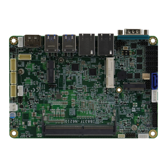
Page 15: Product View
General Information Product View Top View Bottom View *The photos above are for reference only. Some minor components may differ. IB837 User’s Manual... -
Page 16: Dimensions
I/O View Dimensions IB837 User’s Manual... -
Page 17: Chapter 2 Hardware Configuration
Chapter 2 Hardware Configuration This section provides information on jumper settings and connectors on the IB837 in order to set up a workable system. On top of that, you will also need to install crucial pieces such as the CPU and the memory before using the product. The topics covered are: •... -
Page 18: Essential Installations
Follow the instructions below to install the memory. 2.1.1 Installing the Memory The IB837 series supports two DDR4 memory sockets for a maximum total memory of 32 GB. To install the modules, locate the memory slot on the board and perform the following steps: Align the key of the memory module with that on the memory slot and insert the module slantwise. -
Page 19: Setting The Jumpers
Hardware Configuration Setting the Jumpers Set up and configure your IB837 by using jumpers for various settings and features according to your needs and applications. Contact your supplier if you have doubts about the best configuration for your use. 2.2.1 How to Set Jumpers Jumpers are short-length conductors consisting of several metal pins with a non-conductive base mounted on the circuit board. -
Page 20: Jumper & Connector Locations
Jumper & Connector Locations IB837 User’s Manual... -
Page 21: Jumpers Quick Reference
Hardware Configuration Jumpers Quick Reference Jumper / Switch Function Clear CMOS Data Clear ME Register JP2, JP3 LVDS Panel Power Selection JP1, JP4 LVDS Panel Brightness Selection ATX / AT Power Select 2.4.1 Clear CMOS Data (SW1) Function Setting Normal P1-OFF (default) Clear CMOS... -
Page 22: Clear Me Register (Sw1)
2.4.2 Clear ME Register (SW1) Function Setting Normal (default) P2-OFF Clear ME P2-ON 2.4.3 LVDS Panel Power Selection (JP2, JP3) Function Pin closed Illustration 3.3V (default) IB837 User’s Manual... -
Page 23: Lvds Panel Brightness Selection (Jp1, Jp4)
Hardware Configuration 2.4.4 LVDS Panel Brightness Selection (JP1, JP4) Function Pin closed Illustration 3.3V (default) 2.4.5 ATX / AT Power Selection (JP5) Function Pin closed Illustration (default) IB837 User’s Manual... -
Page 24: Connectors Quick Reference
Connectors Quick Reference Connector Function COM1 RS-232/422/485 Port CN3, CN4 I226V LAN Connectors CN5, CN6 USB 3.0 Connectors DP Connector SATA Connector Amplifier Connector SMBus Connector Audio Connector DDR Connector USB 2.0 Connector DC Power Input Connector SATA HDD Power Connector J9, J25 LCD Backlight Connector J14, J10... -
Page 25: Com1 Rs-232/422/485 Port (Cn2)
Hardware Configuration 2.5.1 COM1 RS-232/422/485 Port (CN2) COM1 port is jumper-less and configurable in BIOS. Signal Name Signal Name DCD, Data carrier detect DSR, Data set ready RXD, Receive data RTS, Request to send TXD, Transmit data CTS, Clear to send DTR, Data terminal ready RI, Ring indicator Ground... -
Page 26: I226V Lan Connectors (Cn3, Cn4)
2.5.2 I226V LAN Connectors (CN3, CN4) 2.5.3 USB 3.0 Connectors (CN5, CN6) IB837 User’s Manual... -
Page 27: Dp Connector (Cn7)
Hardware Configuration 2.5.4 DP Connector (CN7) 2.5.5 SATA Connector (CN1) IB837 User’s Manual... -
Page 28: Amplifier Connector (J1)
2.5.6 Amplifier Connector (J1) Assignment Assignment SPK_L+ SPK_R- SPK_L- SPK_R+ 2.5.7 SMBUS Connector (J3) Assignment Assignment +3.3V SMB_DATA SMB_CLK- Ground IB837 User’s Manual... -
Page 29: Audio Connector (J4)
Hardware Configuration 2.5.8 Audio Connector (J4) Assignment Assignment Lineout_L Lineout_R JD_FRONT Ground LINEIN_L Linein_R JD_LINEIN Ground MIC_L MIC-R JD_MIC1 Ground 2.5.9 DDR Connector (J5) IB837 User’s Manual... -
Page 30: Usb 2.0 Connector (J6)
2.5.10 USB 2.0 Connector (J6) Assignment Assignment Ground Ground 2.5.11 DC Power Input Connector (J7) Assignment +12V Ground IB837 User’s Manual... -
Page 31: Sata Hdd Power Connector (J8)
Hardware Configuration 2.5.12 SATA HDD Power Connector (J8) Assignment Assignment Ground Ground +12V 2.5.13 LCD Backlight Connector (J9, J25) Assignment Assignment +12V Brightness Control Backlight Enable Ground IB837 User’s Manual... -
Page 32: Lvds1 Connector (J14: Ch1, J10: Ch2)
2.5.14 LVDS1 Connector (J14: CH1, J10: CH2) Assignment Assignment TX0P TX0P Ground Ground TX1P TX1P Ground Ground TX2P TX2P Ground Ground CLKP CLKP Ground Ground TX3P TX3P IB837 User’s Manual... -
Page 33: Lvds2 Connector (J21: Ch1, J18: Ch2)
Hardware Configuration 2.5.15 LVDS2 Connector (J21: CH1, J18: CH2) Assignment Assignment TX0P TX0N Ground Ground TX1P TX1N Ground Ground TX2P TX2N Ground Ground CLKP CLKN Ground Ground TX3P TX3N IB837 User’s Manual... -
Page 34: B-Key Connector (J11)
2.5.16 M.2 B-Key Connector (J11) 2.5.17 Mini PCIE Connector (J15) IB837 User’s Manual... -
Page 35: E-Key Connector (J16)
Hardware Configuration 2.5.18 M.2 E-Key Connector (J16) 2.5.19 COM2, COM3, COM4, COM5, COM6 RS-232 Ports (J23, J17, J19, J20, J22) Assignment Assignment DCD, Data carrier detect RXD, Receive data TXD, Transmit data DTR, Data terminal ready Ground DSR, Data set ready RTS, Request to send CTS, Clear to send RI, Ring indicator... -
Page 36: Battery Connector (J24)
2.5.20 Battery Connector (J24) Assignment Battery+ Ground IB837 User’s Manual... -
Page 37: Front Panel Connector (J26)
Hardware Configuration 2.5.21 Front Panel Connector (J26) Assignment Assignment Ground PWR_BTN 3.3V HDD Active Ground Reset Ground J26 is utilized for system indicators to provide light indication of the computer activities and switches to change the computer status. It provides interfaces for the following functions. -
Page 38: Digital I/O Connector (J27)
2.5.22 Digital I/O Connector (J27) Assignment Assignment Ground OUT3 OUT1 OUT2 OUT0 2.5.23 CPU Fan Power Connector (CPU_FAN1) Assignment Ground +12V Rotation detection IB837 User’s Manual... -
Page 39: Chapter 3 Drivers Installation
Chapter 3 Drivers Installation This chapter introduces installation of the following drivers: • ® Intel Chipset Software Installation Utility • VGA Driver • HD Audio Driver • LAN Driver • ® Intel Management Engine Drivers Installation... -
Page 40: Intel ® Chipset Software Installation Utility
® Intel Chipset Software Installation Utility ® Note: After installing the Windows operating system, install the Intel Chipset Software Installation Utility first before proceeding with the drivers installation. ® The Intel Chipset drivers should be installed first before the software drivers to install INF files for Plug &... - Page 41 Driver Installation Click Intel(R) Chipset Software Installation Utility. ® When the Welcome screen to the Intel Chipset Device Software appears, click Next. Accept the software license agreement and proceed with the installation process. On the Readme File Information screen, click Install. After the installation, press Finish to complete the setup process.
-
Page 42: Vga Driver Installation
VGA Driver Installation Run the driver disk. Click Intel on the left pane and then Intel(R) Elkhartlake Chipset Drivers on the right pane. Click Intel(R) Elkhartlake Graphics Driver. IB837 User’s Manual... - Page 43 Driver Installation On the intel Graphics Driver Installer screen, click Begin installation. Click I agree. IB837 User’s Manual...
- Page 44 Click Start. Click Finish. IB837 User’s Manual...
-
Page 45: Hd Audio Driver Installation
Driver Installation HD Audio Driver Installation Run the driver disk. Click Intel on the left pane and then Intel(R) Elkhartlake Chipset Drivers on the right pane. Click Realtek High Definition Audio Driver. IB837 User’s Manual... - Page 46 On the Welcome screen, click Next. On the Custom Installation Help screen, click Next. When InstallShield Wizard has finished the installation, click Finish. IB837 User’s Manual...
-
Page 47: Intel® Me Drivers Installation
Driver Installation Intel® ME Drivers Installation Run the driver disk. Click Intel on the left pane and then Intel(R) ME Drivers. On the Welcome screen to the Intel® Management Engine Components, click Next. IB837 User’s Manual... - Page 48 Accept the license agreement and click Next. On the Setup’s Destination Folder screen, click Next to install to the default folder, or click Change to choose another destination folder. After the Intel® Management Engine Components have been installed, click Finish. IB837 User’s Manual...
-
Page 49: Lan Driver Installation
Driver Installation LAN Driver Installation Run the driver disk. Click LAN Card on the left pane and then Intel LAN Controller Drivers on the right pane. Choose Intel(R) I21x/ I22x Gigabit Network Drivers. Click Install Drivers and Software. IB837 User’s Manual... - Page 50 On the welcome screen to the install wizard for Intel(R) Network Connections, click Next. On the Setup Options screen, click Next. Click Install. When Install wizard has completed the installation, click Finish. IB837 User’s Manual...
-
Page 51: Chapter 4 Bios Setup
Chapter 4 BIOS Setup This chapter describes the different settings available in the AMI BIOS that comes with the board. The topics covered in this chapter are as follows: • Main Settings • Advanced Settings • Chipset Settings • Security Settings •... -
Page 52: Introduction
4.1 Introduction The BIOS (Basic Input/Output System) installed in the ROM of your ® computer system supports Intel processors. The BIOS provides critical low-level support for standard devices such as disk drives, serial ports and parallel ports. It also provides password protection as well as special support for detailed fine-tuning of the chipset controlling the entire system. -
Page 53: Main Settings
BIOS Setup 4.3 Main Settings BIOS Setting Description System Date Sets the date. Use the <Tab> key to switch between the date elements. System Time Set the time. Use the <Tab> key to switch between the time elements. IB837 User’s Manual... -
Page 54: Advanced Settings
4.4 Advanced Settings This section allows you to configure, improve your system and allows you to set up some system features according to your preference. 4.4.1 CPU Configuration Displays CPU configuration parameters. IB837 User’s Manual... - Page 55 BIOS Setup 4.4.2 PCH-FW Configuration BIOS Setting Description ME State When disabled ME will be put into ME Temporarily Disabled Mode. 4.4.3 Trusted Computing IB837 User’s Manual...
- Page 56 BIOS Setting Description Security Device Enables / Disables BIOS support for security Support device. OS will not show security device. TCG EFI protocol and INTIA interface will not be available. SHA-1 PCR Bank Enables / Disables SHA-1 PCR Bank. SHA256 PCR Bank Enables / Disables SHA256 PCR Bank.
- Page 57 BIOS Setup 4.4.4 ACPI Settings BIOS Setting Description Enable Hibernation Enables / Disables the system ability to hibernate (OS/S4 Sleep State). This option may be not effective with some OS. ACPI Sleep State Selects an ACPI sleep state (Suspend Disabled or S3) where the system will enter when the Suspend button is pressed.
- Page 58 4.4.5 LVDS (eDP/DP) Configuration BIOS Setting Description LVDS (eDP/DP) Enables / Disables LVDS. Support Panel Color Depth Selects the panel collor depth. Options: 18 bit, 24 Bit (VESA), 24 bit (JEIDA) LVDS Channel Type Chooses the LVDS as single or dual channel. LCD Panel Type Selects LCD panel used by Intel Graphics Device by selecting the appropriate setup item.
- Page 59 BIOS Setup 4.4.6 Super IO Configuration Serial Port 1 Configuration IB837 User’s Manual...
- Page 60 Serial Port 2 Configuration Serial Port 3 Configuration IB837 User’s Manual...
- Page 61 BIOS Setup Serial Port 4 Configuration Serial Port 5 Configuration IB837 User’s Manual...
- Page 62 Serial Port 6 Configuration BIOS Setting Description Serial Ports Configuration Sets parameters of serial ports. Standby Power on S5(ERP) This setting enables or shutdown the standby power for devices. Power on after Power Failure Options: Always on, Always off IB837 User’s Manual...
- Page 63 BIOS Setup 4.4.7 Hardware Monitor BIOS Setting Description Temperatures / These fields are the parameters of the hardware Voltages monitoring function feature of the motherboard. The values are read-only values as monitored by the system and show the PC health status. IB837 User’s Manual...
- Page 64 4.4.8 USB Configuration BIOS Setting Description • Legacy USB Support Enabled enables Legacy USB support. • Auto disables legacy support if there is no USB device connected. • Disabled keeps USB devices available only for EFI applications. XHCI Hand-off This is a workaround for OSes without XHCI hand-off support.
- Page 65 BIOS Setup 4.4.9 Network Stack Configuration BIOS Setting Description Network Stack Enable/Disable UEFI Network Stack IPv4 PXE Support Enable/Disable IPv4 PXE boot support. If disabled, IPv4 PXE boot support will not be available. Ipv4 HTTP Support Enable/Disable Ipv4 HTTP boot support. If disabled, Ipv4 HTTP boot support will not be available.
-
Page 66: Chipset Settings
4.5 Chipset Settings 4.5.1 System Agent (SA) Configuration BIOS Setting Description Primary display Select which of IGFX/PEG/PCI Graphics device should be Primary Display or select HG for Hybrid Gfx Internal Keep IGFX enabled based on the setup options Graphics GTT Size Options: 2MB, 4MB, 8MB Aperture Size Select the Aperture Size. - Page 67 BIOS Setup 4.5.2 PCH-IO Configuration BIOS Setting Description SATA Controller(s) Enables / Disables the Serial ATA. SATA Mode Selection Selects IDE or AHCI Mode. Serial ATA Port 0~2 Enables / Disables Serial Port 0~1. SATA Ports Hot Plug Enables / Disables SATA Ports HotPlug. IB837 User’s Manual...
-
Page 68: Security Settings
4.6 Security Settings BIOS Setting Description Setup Administrator Sets an administrator password for the setup Password utility. User Password Sets a user password. Secure Boot Secure Boot feature is Active if Secure Boot is Enabled. Platform Key(PK) is enrolled and the System is in User mode. - Page 69 BIOS Setup Restore Factory Keys Key Management Factory Key Provision Restore Factory Keys Enroll Efi Image IB837 User’s Manual...
- Page 70 Restore DB defaults Secure Boot Variables IB837 User’s Manual...
-
Page 71: Boot Settings
BIOS Setup 4.7 Boot Settings BIOS Setting Description Setup Prompt Number of seconds to wait for setup activation Timeout key. 65535 (0xFFFF) means indefinite waiting. Bootup NumLock Selects the keyboard NumLock state. State Quiet Boot Enables / Disables Quiet Boot option. Boot Option Priorities Sets the system boot order priorities for hard disk, CD/DVD, USB, Network. -
Page 72: Save & Exit Settings
4.8 Save & Exit Settings BIOS Setting Description Save Changes Exits system setup after saving the changes. and Exit Discard Changes Exits system setup without saving any changes. and Exit Save Changes Resets the system after saving the changes. and Reset Discard Changes Resets system setup without saving any changes. -
Page 73: Appendix
Appendix This section provides the mapping addresses of peripheral devices and the sample code of watchdog timer configuration. -
Page 74: I/O Port Address Map
I/O Port Address Map Each peripheral device in the system is assigned a set of I/O port addresses which also becomes the identity of the device. The following table lists the I/O port addresses used. Address Device Description 0x00000A00-0x00000A0F Motherboard resources 0x00000A10-0x00000A1F Motherboard resources 0x00000A20-0x00000A2F... - Page 75 Appendix Address Device Description 0x00000020-0x00000021 Programmable interrupt controller 0x00000024-0x00000025 Programmable interrupt controller 0x00000028-0x00000029 Programmable interrupt controller 0x0000002C-0x0000002D Programmable interrupt controller 0x00000030-0x00000031 Programmable interrupt controller 0x00000034-0x00000035 Programmable interrupt controller 0x00000038-0x00000039 Programmable interrupt controller 0x0000003C-0x0000003D Programmable interrupt controller 0x000000A0-0x000000A1 Programmable interrupt controller 0x000000A4-0x000000A5 Programmable interrupt controller 0x000000A8-0x000000A9...
-
Page 76: Interrupt Request Lines (Irq)
Interrupt Request Lines (IRQ) Peripheral devices use interrupt request lines to notify CPU for the service required. The following table shows the IRQ used by the devices on board. Level Function IRQ 0 System timer IRQ 1 Standard PS/2 Keyboard IRQ 3 Communications Port (COM2) IRQ 4... -
Page 77: Watchdog Timer Configuration
Appendix Watchdog Timer Configuration The Watchdog Timer (WDT) is used to generate a variety of output signals after a user programmable count. The WDT is suitable for use in the prevention of system lock-up, such as when software becomes trapped in a deadlock. - Page 78 bTime = strtol (argv[1], endptr, 10); printf("System will reset after %d seconds\n", bTime); if (bTime) EnableWDT(bTime); } else DisableWDT(); } return 0; //--------------------------------------------------------------------------- void EnableWDT(int interval) unsigned char bBuf; bBuf = Get_F81966_Reg(0x2B); bBuf &= (~0x20); Set_F81966_Reg(0x2B, bBuf); //Enable WDTO Set_F81966_LD(0x07); //switch to logic device 7 Set_F81966_Reg(0x30, 0x01);...
- Page 79 Appendix // THIS CODE AND INFORMATION IS PROVIDED "AS IS" WITHOUT WARRANTY OF ANY // KIND, EITHER EXPRESSED OR IMPLIED, INCLUDING BUT NOT LIMITED TO THE // IMPLIED WARRANTIES OF MERCHANTABILITY AND/OR FITNESS FOR A PARTICULAR // PURPOSE. //--------------------------------------------------------------------------- #include "F81966.H" #include <dos.h>...
- Page 80 //--------------------------------------------------------------------------- void Set_F81966_Reg( unsigned char REG, unsigned char DATA) Unlock_F81966(); outportb(F81966_INDEX_PORT, REG); outportb(F81966_DATA_PORT, DATA); Lock_F81966(); //--------------------------------------------------------------------------- unsigned char Get_F81966_Reg(unsigned char REG) unsigned char Result; Unlock_F81966(); outportb(F81966_INDEX_PORT, REG); Result = inportb(F81966_DATA_PORT); Lock_F81966(); return Result; //--------------------------------------------------------------------------- //--------------------------------------------------------------------------- // THIS CODE AND INFORMATION IS PROVIDED "AS IS" WITHOUT WARRANTY OF ANY // KIND, EITHER EXPRESSED OR IMPLIED, INCLUDING BUT NOT LIMITED TO THE // IMPLIED WARRANTIES OF MERCHANTABILITY AND/OR FITNESS FOR A PARTICULAR // PURPOSE.
-
Page 81: Onboard Connector Reference Types
Appendix Onboard Connector Reference Types Compatible Mating Function Connector Onboard Type Type Hao Guo Xing Ye Hirose Audio Connector DF11-12S-PA66H DF11-12DS-2C SATA HDD E-call Power 0110-071-040 XHP-4 Connector Front Panel Dupont Dupon Setting 2.54 mm-pitch pin 2.54 mm-pitch (Female) Connector header (Male) USB 2.0 Hao Guo Xing Ye...
Need help?
Do you have a question about the IB837 Series and is the answer not in the manual?
Questions and answers