Table of Contents
Advertisement
Quick Links
Advertisement
Table of Contents

Related Manuals for IBASE Technology SI-22-415


Summary of Contents for IBASE Technology SI-22-415
- Page 1 SI-22 Series User Manual IBASE Technology Inc.
- Page 2 SI-22 User Manual Revision Release Date V0.1 2013/12/02 V0.2 2014/02/25 V0.3 2014/04/01 V0.4 2014/10/22 V0.5 2015/01/30 V1.0 2015/09/04 Copyright © 2013 IBASE Technology Inc. All Rights Reserved.
- Page 3 SI-22 User Manual Copyright © 2013 IBASE Technology Inc. All Rights Reserved. No part of this manual, including the products and software described in it, may be reproduced, transmitted, transcribed, stored in a retrieval system, or translated into any language in any form or by any means, except documentation kept by the purchaser for backup purposes, without the express written permission of IBASE Technology INC.
-
Page 4: Table Of Contents
SI-22 User Manual Table of Contents Setting up your system ......................3 Care during use ........................4 Acknowledgments ....................... 5 CHAPTER 1 INTRODUCTION ..................6 1.1 General Description ....................... 6 1.2 System Specifications..................... 6 1.2.1 Hardware Specifications……………………………………………………………………………………….7 1.2.2 Dimensions ......................... 8 1.2.3 I/O View ........................ -
Page 5: Setting Up Your System
SI-22 User Manual Safety Information Your SI-22 is designed and tested to meet the latest standards of safety for information technology equipment. However, to ensure your safety, it is important that you read the following safety instructions Setting up your system ... -
Page 6: Care During Use
SI-22 User Manual Care during use Do not walk on the power cord or allow anything to rest on it. Do not spill water or any other liquids on your system. When the system is turned off, a small amount of electrical current still flows. Always unplug all power, and network cables from the power outlets before cleaning the system. -
Page 7: Acknowledgments
FINTEK is a registered trademark of FINTEK Electronics Corporation. REALTEK is a registered trademark of REALTEK Electronics Corporation. All other product names or trademarks are properties of their respective owners. Copyright © 2013 IBASE Technology Inc. All Rights Reserved. -
Page 8: Chapter 1 Introduction
SI-22 User Manual CHAPTER 1 INTRODUCTION 1.1 General Description The “Signature Book™” SI-22 is a professional fanless digital signage system powered by the new AMD Embedded new generation G-Series quad-core APU with DASH compliance for remote control, and compact & slim design. It supports 2x HDMI, 1x RJ45 for LAN, 1x RJ45 for RS232, 1x USB2.0 and 2x USB3.0 ports to give a wide selection for data communication in display applications. -
Page 9: System Specifications
-20° ~ 80°C (-4°F~176°F) Relative Humidity 5~90% @45°C (non-condensing) Vibration mSATA: 5 Grms/5~500Hz random operation RoHS Available Certification CE, FCC, UL, CCC ‧ This specification is subject to change without prior notice. Copyright © 2013 IBASE Technology Inc. All Rights Reserved. -
Page 10: Dimensions
SI-22 User Manual 1.2.2 Dimensions... -
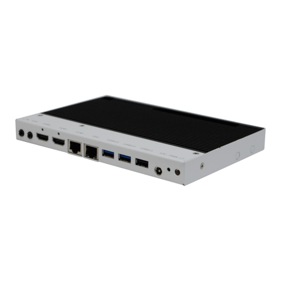
Page 11: I/O View
1.2.3 I/O View Item Connector Item Connector Line-in 2x USB 3.0 Line-out 1x USB 2.0 2x HDMI 1.4a DC jack 1x RJ45 for RS232 Power LED 1x RJ45 for LAN Power on/off button Copyright © 2013 IBASE Technology Inc. All Rights Reserved. -
Page 12: Exploded View Of The Si-22 Assembly
SI-22 User Manual 1.3 Exploded View of the SI-22 Assembly 1.3.1 Parts Description Part No. Description Part No. Description IB922 motherboard SI-22 Base SI-22 Cover SI-22 heatsink 1.4 Packing List Item No. Description Driver CD Power adaptor Power Cord... -
Page 13: Optional Items
EDID Emulator Dongle (HDMI), ADAPTER; H8246JT021-001 HDMI 19P A/M TO A/F (A025HDMI001010000P) Mounting Kit Description Component BOM; SI-12 & SI-22 V-A1 HDMI Cable Holder with Screw RoHS HDMI Cable Holder (SC2SI12----0A1100P) Copyright © 2013 IBASE Technology Inc. All Rights Reserved. -
Page 14: Hardware Installation
SI-22 User Manual 1.5 HARDWARE INSTALLATION 1.5.1 Installing the optional Wireless Module 1. Remove the six screws on the sides that are used to secure the white cover to the chassis. Once all the screws are removed, from the side, push the cover forward to remove it. - Page 15 IBASE Technology Inc. 2. Push the WIFI module into the slot. Screw two screws to secure the module in the slot. Copyright © 2013 IBASE Technology Inc. All Rights Reserved.
-
Page 16: Installing The Msata Module
SI-22 User Manual 1.5.2 Installing the mSATA Module 1. Remove the six screws on the sides that are used to secure the white cover to the chassis. Once all the screws are removed, from the side, push the cover forward to remove it. - Page 17 IBASE Technology Inc. 2. Push the mSATA module into the slot. Screw two screws to secure the module in the slot. Copyright © 2013 IBASE Technology Inc. All Rights Reserved.
-
Page 18: Installing The Hdmi Cable Holder
SI-22 User Manual 1.5.3 Installing the Optional HDMI cable holder Install the HDMI cable holder and screw two M3 screws as shown. -
Page 19: Chapter 2 Motherboard Introduction
2. Gently push the DDR3 module in an upright position until the clips of the slot close to hold the DDR3 module in place when the DDR3 module touches the bottom of the slot. 3. To remove the DDR3 module, press the clips with both hands. Copyright © 2013 IBASE Technology Inc. All Rights Reserved. -
Page 20: Setting The Jumpers
SI-22 User Manual 2.2 Setting the Jumpers Jumpers are used on IB922 to select various settings and features according to your needs and applications. Contact your supplier if you have doubts about the best configuration for your needs. The following lists the jumper and connectors on IB922 and their respective functions. -
Page 21: Connectors On Ib922
GND, ground RXD, Receive data DSR, Data set ready CTS, Clear to send CN3, CN4: USB 3.0 Connector CN5: USB 2.0 Connector CN6: Board Input Power Connector CN7, CN8: HDMI Connector Copyright © 2013 IBASE Technology Inc. All Rights Reserved. - Page 22 SI-22 User Manual J1: SPI Flash Connector (factory use only) J2: Mini PCIE Connector (with USB SIM support) J3: Battery Connector J6: DDR3 SO-DIMM Socket J7: Mini PCIE Connector (w/ M-SATA support) J11: Audio LINE_IN Connector J12: Audio LINE_OUT Connector LED6: Power On LED...
-
Page 23: Chapter 3 Bios Setup
<PgDn> keys to change entries, <F1> for help and <Esc> to quit. When you enter the Setup utility, the Main Menu screen will appear on the screen. The Main Menu allows you to select from various setup functions and exit choices. Copyright © 2013 IBASE Technology Inc. All Rights Reserved. - Page 24 SI-22 User Manual Main Settings Aptio Setup Utility – Copyright © 2011 American Megatrends, Inc. Main Advanced Chipset Boot Security Save & Exit Choose the system BIOS Information default language Memory Information → ← Select Screen Total memory 8176 MB (DDR3) ↑↓...
- Page 25 Value to be programmed into PCI Latency Timer Register. VGA Palette Snoop Enables or disables VGA Palette Registers Snooping. PERR# Generation Enables or disables PCI device to generate PERR#. SERR# Generation Enables or disables PCI device to generate SERR#. Copyright © 2013 IBASE Technology Inc. All Rights Reserved.
- Page 26 SI-22 User Manual PCI Express Settings Aptio Setup Utility Advanced Main Chipset Boot Security Save & Exit PCI Express Device Register Settings Relaxed Ordering Disabled Extended Tag Disabled No Snoop Enabled Maximum Payload Auto Maximum Read Request Auto PCI Express Link Register Settings ASPM Support Disabled →...
- Page 27 Provide to adjust _PPC object. NX Mode Enable/disable No-execute page protection function. SVM Mode Enable/disable CPU Virtualization. CPB Mode Enable/disable CPB. C6 Mode Auto/disable CPB. Node 0 Information View memory information related to Node 0. Copyright © 2013 IBASE Technology Inc. All Rights Reserved.
- Page 28 SI-22 User Manual IDE Configuration Aptio Setup Utility Main Advanced Chipset Boot Security Save & Exit IDE Configuration → ← Select Screen ↑↓ Select Item SATA Port0 InnoLite CFast (16.0GB) Enter: Select +- Change Field SATA Port2 Not Present F1: General Help F2: Previous Values F3: Optimized Default F4: Save...
- Page 29 Maximum time the device will take before it properly reports itself to the Host Controller. ‘Auto’ uses default value: for a Root port it is 100ms, for a Hub port the delay is taken from Hub descriptor. Copyright © 2013 IBASE Technology Inc. All Rights Reserved.
- Page 30 SI-22 User Manual F81866 Super IO Configuration Aptio Setup Utility Main Advanced Chipset Boot Security Save & Exit F81866 Super IO Configuration → ← Select Screen ↑↓ Select Item F81866 Super IO Chip F81866 Enter: Select ► Serial Port 0 Configuration +- Change Field F1: General Help ►...
- Page 31 Smart Fan Function This field enables or disables the smart fan feature. At a certain temperature, the fan starts turning. Once the temperature drops to a certain level, it stops turning again. Copyright © 2013 IBASE Technology Inc. All Rights Reserved.
- Page 32 SI-22 User Manual Chipset Settings This section allows you to configure and improve your system and allows you to set up some system features according to your preference. Aptio Setup Utility Main Advanced Chipset Boot Security Save & Exit → ← Select Screen ►...
- Page 33 OnChip SATA Type Native IDE /n RAID /n AHCI /n AHCI /n Legacy IDE /n IDE->AHCI /n HyperFlash OnChip IDE mode Legacy mode or Native mode SATA IDE Combined Mode Enabled or Disabled. Copyright © 2013 IBASE Technology Inc. All Rights Reserved.
- Page 34 SI-22 User Manual SB USB Configuration Options: Chipset Main Advanced Boot Security Save & Exit XHCI Controller 0 Enabled XHCI Controller 1 Enabled DHCI HC(Bus 0 Dev 18 Fn 0) Enabled EHCI HC(Bus 0 Dev 18 Fn 2) Enabled DHCI HC(Bus 0 Dev 19 Fn 0) Enabled EDHCI HC(Bus 0 Dev 19 Fn 0) Enabled...
- Page 35 ↑↓ Select Item Enter: Select Ending Address: 8388607 KB +- Change Field F1: General Help Dimm0: Not Present F2: Previous Values F3: Optimized Default Dimm1: size=8192 MB, speed=667 MHz F4: Save ESC: Exit Copyright © 2013 IBASE Technology Inc. All Rights Reserved.
- Page 36 SI-22 User Manual Boot Settings Aptio Setup Utility Main Advanced Chipset Boot Security Save & Exit Boot Configuration Setup Prompt Timeout Bootup NumLock State Quiet Boot Disabled Fast Boot Disabled CSM16 Module Version 07.69 GateA20 Active Upon Request → ← Select Screen Option ROM Messages Force BIOS ↑↓...
- Page 37 Launch Video OpROM policy Controls the execution of UEFI and Legacy Video OpROM. Other PCI device ROM priority For PCI devices other than Network, Mass storage or Video defines which OpROM to launch. Copyright © 2013 IBASE Technology Inc. All Rights Reserved.
- Page 38 SI-22 User Manual Security Settings This section allows you to configure and improve your system and allows you to set up some system features according to your preference. Aptio Setup Utility Main Advanced Chipset Boot Security Save & Exit Password Description If ONLY the Administrator’s password is set, then this only limit access to Setup and is only asked for when entering Setup.
- Page 39 Restore User Defaults Restore the User Defaults to all the setup options. Launch EFI Shell from filesystem device Attempts to launch EFI Shell application (Shellx64.efi) from one of the available filesystem devices. Copyright © 2013 IBASE Technology Inc. All Rights Reserved.
-
Page 40: Chapter 4 Drivers Installation
SI-22 User Manual CHAPTER 4 DRIVERS INSTALLATION This section describes the installation procedures for software and drivers. The software and drivers are included with your package. If you find the items missing, please contact the vendor where you made the purchase. IMPORTANT NOTE: After installing your Windows operating system, you must install first the Intel Chipset Software Installation Utility before proceeding with the drivers installation. - Page 41 IBASE Technology Inc. 3. When the welcome screen appears, click Next. 4. Select the language you would like to be displayed and click Next. 5. Click Install to continue the installation process. Copyright © 2013 IBASE Technology Inc. All Rights Reserved.
- Page 42 SI-22 User Manual 6. Select Express and the installation location and click Next.
- Page 43 IBASE Technology Inc. 7. Click Accept to accept the End User License Agreement. 8. To reboot the system, click Yes. Copyright © 2013 IBASE Technology Inc. All Rights Reserved.
-
Page 44: Realtek Hd Audio Driver Installation
SI-22 User Manual 4.2 Realtek HD Audio Driver Installation 1. Click Realtek High Definition Audio Driver. 2. On the Welcome to the InstallShield Wizard screen, click Next to proceed with and complete the installation process. 3. Restart the computer when prompted. -
Page 45: Lan Drivers Installation
5. Click the checkbox for Drivers in the Setup Options screen to select it and click Next to continue. 6. When the Ready to Install the Program screen appears, click Install to continue. 7. When InstallShield Wizard is complete, click Finish. Copyright © 2013 IBASE Technology Inc. All Rights Reserved. -
Page 46: Appendix
SI-22 User Manual Appendix Mounting SI-22 to the Wall You can install SI-22 on plastic (LCD monitor), wood, drywall surface over studs, or a solid concrete or metal plane directly. Ensure the installer uses at least two M3 length 6mm screws to secure the system on the wall. Four M3 length 6mm screws are recommended to secure the system onto the wall. -
Page 47: Wall Mounting Requirements
This recommendation reduces the risk that someone may accidentally walk into and damage the device. Local laws governing the safety of individuals might require this type of consideration. Copyright © 2013 IBASE Technology Inc. All Rights Reserved. -
Page 48: Mounting Bracket Solution
SI-22 User Manual SI-22 Mounting Bracket Solution SI-22 mounting bracket (IBASE) part number: SC2SIMK1---0A1100P 1. Please install SI-22 to the mounting bracket using 4 screws, as shown in the picture. 2. Please install mounting bracket to the mounting hole of display which you use. Depending on the application, there are different orienations, as shown below. - Page 49 IBASE Technology Inc. 4. After completing the above steps, you can now put the display on the desired location. Copyright © 2013 IBASE Technology Inc. All Rights Reserved.
Need help?
Do you have a question about the SI-22-415 and is the answer not in the manual?
Questions and answers