
Related Manuals for IBASE Technology IB990


Summary of Contents for IBASE Technology IB990
- Page 1 IB990 ® ® Intel Xeon E3 v5 Family Gen. Core™ i7/i5/i3 Full-Size CPU Card User’s Manual Version 1.1 (Dec. 2016)
- Page 2 No part of this publication may be reproduced, copied, stored in a retrieval system, translated into any language or transmitted in any form or by any means, electronic, mechanical, photocopying, or otherwise, without the prior written consent of IBASE Technology, Inc. (hereinafter referred to as “IBASE”). Disclaimer IBASE reserves the right to make changes and improvements to the products described in this document without prior notice.
-
Page 3: Compliance
0.1% by weight (1000 ppm) except for cadmium, limited to 0.01% by weight (100 ppm). • Lead (Pb) • Mercury (Hg) • Cadmium (Cd) • Hexavalent chromium (Cr6+) • Polybrominated biphenyls (PBB) • Polybrominated diphenyl ether (PBDE) IB990 User’s Manual... -
Page 4: Important Safety Information
Danger of explosion if the internal lithium-ion battery is replaced by an incorrect type. Replace only with the same or equivalent type recommended by the manufacturer. Dispose of used batteries according to the manufacturer’s instructions or recycle them at a local recycling facility or battery collection point. IB990 User’s Manual... -
Page 5: Warranty Policy
Software in use (such as OS and application software, including the version numbers) If repair service is required, you can download the RMA form at http://www.ibase.com.tw/english/Supports/RMAService/. Fill out the form and contact your distributor or sales representative. IB990 User’s Manual... -
Page 6: Table Of Contents
2.1.2 Installing the Memory ............13 Setting the Jumpers ................14 2.2.1 How to Set Jumpers ............14 Jumper & Connector Locations on IB990 .......... 15 Jumpers Quick Reference ..............16 2.4.1 Clear CMOS Content (JBAT1) ..........16 2.4.2 COM1 RS232 Power Setting (JP1) ........17 2.4.3... - Page 7 USB Configuration ..............60 Chipset Settings ................62 4.5.1 System Agent (SA) Configuration .........63 4.5.2 Graphics Configuration ............64 4.5.3 Memory Configuration ............65 4.5.4 PCH-IO Configuration ............66 Security Settings ................67 Boot Settings ..................68 Save & Exit Settings ................69 Appendix ..................71 IB990 User’s Manual...
- Page 8 I/O Port Address Map ............... 72 Interrupt Request Lines (IRQ) ............73 Watchdog Timer Configuration ............74 IB990 User’s Manual viii...
-
Page 9: Chapter 1 General Information
Chapter 1 General Information The information provided in this chapter includes: Features Packing List Optional Accessories Block Diagram Specifications Board Overview Board Dimensions... -
Page 10: Introduction
Introduction The IB990 PICMG1.3 SHB Express CPU Card is based on the latest ® ® ® Intel Q170, C236. The platform supports 6 Gen. Intel Xeon E3 v5 family or Core™ i7/i5/i3 DT processors with speeds of up to 4.0GHz and features an integrated graphics core that work with CRT, DVI-I and DVI-D display outputs. -
Page 11: Packing List
General Information Packing List Your IB990 package should include the items listed below. If any of the items below is missing, contact the distributor or dealer from whom you purchased the product. The IB990 PICMG1.3 SHB x 1 ... -
Page 12: Specifications
DDR4-2133 MHz at 1.2V Memory 2 x UDIMM (288-pin vertical type), Max. 32GB * ECC will be supported by identified CPU SKUs. iAMT 11.0 Watchdog Yes (256 segments, 0, 1, 2…255 sec / min) Timer BIOS AMI BIOS IB990 User’s Manual... - Page 13 3 x USB 3.0 host controller (PCH-H integrated) 1 port via the rear panel I/O 2 ports via on board box header ® Intel PCH-H built-in high definition audio with Realtek ALC662 Codec Audio Supports 5.1 channel IB990 User’s Manual...
- Page 14 Supports PCIe (x1) signal Display ® ® ® Intel Xeon E3 v5 family or Intel Gen. Core i7/i5/i3 DT processors integrated graphics 1 x DVI-I 1 x CRT (header on board) 1 x DVI-D (header on board) IB990 User’s Manual...
- Page 15 Product Name (for Q170) (for C236) Environment Operation: 0 ~ 60 °C Temperature Storage: -20 ~ 80 °C Humidity Relative humidity: 0 ~ 90 %, non-condensing All specifications are subject to change without prior notice. IB990 User’s Manual...
-
Page 16: Block Diagram
Block Diagram IB990 User’s Manual... -
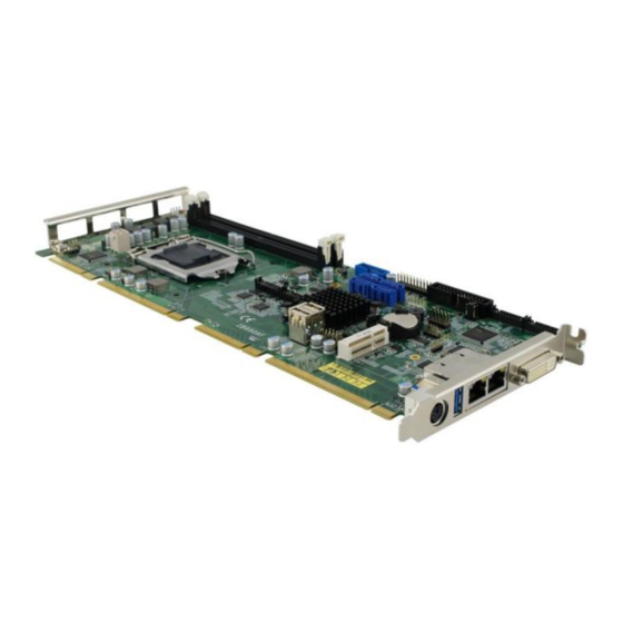
Page 17: Overview
General Information Overview Top View Photo of IB990AF (for Q170) Photo of IB990AF-C236 (for C236) I/O View *The photos above are for reference only. Some minor components may differ. IB990 User’s Manual... -
Page 18: Dimensions
Dimensions REMOVE 186.56 338.58 14.5 13.45 Board diagram of IB990AF (for Q170) IB990 User’s Manual... -
Page 19: Chapter 2 Hardware Configuration
Hardware Configuration This section provides information on jumper settings and connectors on the IB990 in order to set up a workable system. On top of that, you will also need to install crucial pieces such as the CPU and the memory before using the product. The topics covered are: ... -
Page 20: Essential Installations Before You Begin
Essential Installations Before You Begin Follow the instructions below to install the CPU and the memory. 2.1.1 Installing the CPU The IB990 board supports an LGA1151 Socket (shown below) for ® ® ® Intel Xeon E3 v5 family or Intel Gen. -
Page 21: Installing The Memory
Hardware Configuration 2.1.2 Installing the Memory The IB990 board supports two DDR4 memory socket for a maximum total memory of 32GB in DDR4 UDIMM memory type. To install the modules, locate the memory slot on the board and perform the... -
Page 22: Setting The Jumpers
Setting the Jumpers Set up and configure your IB990 by using jumpers for various settings and features according to your needs and applications. Contact your supplier if you have doubts about the best configuration for your use. 2.2.1 How to Set Jumpers Jumpers are short-length conductors consisting of several metal pins with a non-conductive base mounted on the circuit board. -
Page 23: Jumper & Connector Locations On Ib990
Hardware Configuration Jumper & Connector Locations on IB990 REMOVE Board diagram of IB990AF (for Q170) IB990 User’s Manual... -
Page 24: Jumpers Quick Reference
Jumpers Quick Reference Function Jumper Name Page Clear CMOS Content JBAT1 COM1 RS-232 Power Setting PCIe (x16) Bifurcation Selection JP4, JP5 2.4.1 Clear CMOS Content (JBAT1) Function Pin closed Illustration Normal Clear CMOS IB990 User’s Manual... -
Page 25: Com1 Rs232 Power Setting (Jp1)
Hardware Configuration 2.4.2 COM1 RS232 Power Setting (JP1) Function Pin closed Illustration +12V IB990 User’s Manual... -
Page 26: Pcie (X16) Bifurcation Selection (Jp4 & Jp5)
PCIe (x16) Bifurcation Selection (JP4 & JP5) JP4: JP5: Function Pin closed Illustration JP4: Open 1 x PCIe (x16) JP5: Open JP4: Open 2 x PCIe (x8) JP5: Close JP4: Close 1 x PCIe (x8) 2 x PCIe (x4) JP5: Close IB990 User’s Manual... -
Page 27: Connectors Quick Reference
USB3.0 / USB 2.0 Connector USB2.0 Connectors Front Panel Function Connector External Audio Connector ATX 12V Power Connector Digital I/O 4 In/4 Out DVI-D Port Parallel Port VGA Port CPU Fan Power Connector CPU_FAN1 System Fan1 Power Connector SYS_FAN1 IB990 User’s Manual... -
Page 28: Com1 And Com2 Serial Port (J2)
2.5.1 COM1 and COM2 Serial Port (J2) Pin # Assigment Pin # Assigment DCD1 DCD2 DSR1 DSR2 RXD1 RXD2 RTS1 RTS2 TXD1 TXD2 CTS1 CTS2 DTR1 DTR2 Ground Ground IB990 User’s Manual... -
Page 29: Com3, Com4 Serial Port (J3)
Hardware Configuration 2.5.2 COM3, COM4 Serial Port (J3) Pin # Assigment Pin # Assigment DCD3 DCD4 DSR3 DSR4 RXD3 RXD4 RTS3 RTS4 TXD3 TXD4 CTS3 CTS4 DTR3 DTR4 Ground Ground IB990 User’s Manual... -
Page 30: Usb3.0/2.0 Connector (J5)
2.5.3 USB3.0/2.0 Connector (J5) Pin # Assigment Pin # Assigment VCC(900mA) P2_U2_D+ P1_SSRX- P2_U2_D- P1_SSRX+ P2_SSTX+ P1_SSTX- P2_SSTX- P1_SSTX+ P2_SSRX+ P1_U2_D- P2_SSRX- P1_U2_D+ VCC(900mA) IB990 User’s Manual... -
Page 31: Usb2.0 Connectors (J17)
Hardware Configuration 2.5.4 USB2.0 Connectors (J17) Pin # Assigment Pin # Assigment VCC (500mA) VCC (500mA) Ground Ground IB990 User’s Manual... -
Page 32: Front Panel Function Connector (J1)
2.5.5 Front Panel Function Connector (J1) Pin # Assigment Pin # Assigment Ground Speaker Out Ground PWR_SW Ground Ground Ground Ground HDD LED + HDD LED - IB990 User’s Manual... -
Page 33: External Audio Connector (J8)
J8 is a 12-pin header that is used to connect to the optional audio cable. Pin # Assigment Pin # Assigment Line out_L JD_LINE IN Line out_R Ground JD_FRONT MIC-L Ground MIC-R LINE IN_L JD_MIC1 Line in_R Ground IB990 User’s Manual... -
Page 34: Atx 12V Power Connector (J16)
ATX 12V Power Connector (J16) J16 connector supplies the CPU operating voltage. Pin # Assigment Pin # Assigment Ground +12V-IN Ground +12V-IN 2.5.8 Digital I/O 4 In/4 Out (J9) Pin # Assigment Pin # Assigment OUT0 OUT3 OUT1 OUT2 IB990 User’s Manual... -
Page 35: Dvi-D Port (J13)
J13 is a 20-pin header used to connect to the optional DVI-D cable. Pin # Assigment Pin # Assigment TDC1_B TDC2_B TDC1#_B TDC2#_B Ground Ground Ground Ground TLC_B TDC0_B TLC#_B TDC0#_B Ground N.C. N.C. HPDET_B SD_DDC_B N.C. SC_DDC_B IB990 User’s Manual... -
Page 36: Parallel Port (J6)
PD2, parallel data 2 Select PD3, parallel data 3 Ground PD4, parallel data 4 Ground PD5, parallel data 5 Ground PD6, parallel data 6 Ground PD7, parallel data 7 Ground ACK, acknowledge Ground Busy Ground Paper empty Ground Select Ground IB990 User’s Manual... -
Page 37: Vga Port (J14)
Hardware Configuration 2.5.11 VGA Port (J14) J14 is a 16-pin header used to connect to the optional VGA port cable. Pin # Assigment Pin # Assigment CRT1_RED Ground CRT1_HSYN_R CRT1_GREEN Ground Ground CRT1_VSYN_R CRT1_BLUE Ground CRT1_DDC_CLK_ISO Ground CRT1_DDC_DATA_ISO IB990 User’s Manual... -
Page 38: Cpu Fan Power Connector (Cpu_Fan1)
2.5.12 CPU Fan Power Connector (CPU_FAN1) Pin # Assigment Pin # Assigment Ground Rotation detection +12V(1A) Control 2.5.13 System Fan1 Power Connector (SYS_FAN1) Pin # Assigment Pin # Assigment Ground Rotation detection +12V(1A) IB990 User’s Manual... -
Page 39: Chapter 3 Drivers Installation
Chapter 3 Drivers Installation This chapter introduces installation of the following drivers: ® Intel Chipset Software Installation Utility VGA Driver HD Audio Driver LAN Driver ® Intel Management Engine Interface ® Intel USB 3.0 Driver... -
Page 40: Introduction
If you find anything missing, please contact the distributor where you made the purchase. The contents of this section include the following: Note: After installing your Windows operating system, you must install first the Intel Chipset Software Installation Utility before proceeding with the drivers installation. IB990 User’s Manual... -
Page 41: Intel ® Chipset Software Installation Utility
Intel(R) Skylake Chipset Drivers. Click Intel(R) Chipset Software Installation Utility. ® When the Welcome screen to the Intel Chipset Device Software appears, click Next to continue. Click Yes to accept the software license agreement and proceed with the installation process. IB990 User’s Manual... - Page 42 On the Readme File Information screen, click Install for installation. The driver has been completely installed. Click Finish to restart the computer and for changes to take effect. IB990 User’s Manual...
-
Page 43: Vga Driver Installation
Driver Installation VGA Driver Installation Insert the disk enclosed in the package with the board. Click Intel and then Intel(R) Skylake Chipset Drivers. Click Intel(R) HD Graphics Driver. IB990 User’s Manual... - Page 44 When the Welcome screen appears, click Next to continue. Click Yes to agree with the license agreement and continue the installation. IB990 User’s Manual...
- Page 45 Driver Installation On the Windows Security screen shown below, click Install to continue. The driver has been completely installed. Click Finish to restart the computer and for changes to take effect. IB990 User’s Manual...
-
Page 46: Hd Audio Driver Installation
HD Audio Driver Installation Insert the disk enclosed in the package with the board. Click Intel and then Intel(R) Skylake Chipset Drivers. Click Realtek High Definition Audio Driver. IB990 User’s Manual... - Page 47 Driver Installation On the Welcome screen of the InstallShield Wizard, click Next for installation. The installation is complete. Click Finish to restart the computer and for changes to take effect. IB990 User’s Manual...
-
Page 48: Lan Driver Installation
LAN Driver Installation Insert the disk enclosed in the package with the board. Click Intel and then Intel(R) Skylake Chipset Drivers. Click Intel(R) PRO LAN Network Drivers. IB990 User’s Manual... - Page 49 Driver Installation ® On the screen of Intel Network Connections, click Install Drivers and Software. When the Welcome screen appears, click Next. Click Next to to agree with the license agreement. IB990 User’s Manual...
- Page 50 On the Setup Options screen, click the checkbox to select the desired driver(s) for installation. Then click Next to continue. The wizard is ready for installation. Click Install. As the installation is complete, click Finish. Click Finish to restart the computer and for changes to take effect. IB990 User’s Manual...
-
Page 51: Intel ® Management Engine Interface
Click Next to to agree with the license agreement. When the Setup Progress screen appears, click Next. As the driver has been sccessfully installed, click Finish. Click Finish to restart the computer and for changes to take effect. IB990 User’s Manual... -
Page 52: Intel ® Usb 3.0 Driver
® Intel USB 3.0 Driver Insert the disk enclosed in the package with the board. Click Intel and then Intel(R) Skylake Chipset Drivers. Click Intel(R) USB 3.0 Drivers. IB990 User’s Manual... - Page 53 Click Next to to agree with the license agreement. On the Readme File Information screen, click Next for installation. The driver has been successfully installed. Click Finish to restart the computer and for changes to take effect. IB990 User’s Manual...
- Page 54 This page is intentionally left blank. IB990 User’s Manual...
-
Page 55: Chapter 4 Bios Setup
Chapter 4 BIOS Setup This chapter describes the different settings available in the AMI BIOS that comes with the board. The topics covered in this chapter are as follows: Main Settings Advanced Settings Chipset Settings Security Settings ... -
Page 56: Introduction
The following message will appear on the screen: Press <DEL> Enter Setup In general, press the arrow keys to highlight items, <Enter> to select, the <PgUp> and <PgDn> keys to change entries, <F1> for help, and <Esc> to quit. IB990 User’s Manual... - Page 57 These defaults have been carefully chosen by both AMI and your system manufacturer to provide the absolute maximum performance and reliability. Changing the defaults could make the system unstable and crash in some cases. IB990 User’s Manual...
-
Page 58: 4.3 Main Settings
4.3 Main Settings BIOS Setting Description System Date Sets the date. Use the <Tab> key to switch between the data elements. System Time Set the time. Use the <Tab> key to switch between the data elements. IB990 User’s Manual... -
Page 59: 4.4 Advanced Settings
BIOS Setup 4.4 Advanced Settings This section allows you to configure, improve your system and allows you to set up some system features according to your preference. IB990 User’s Manual... -
Page 60: Trusted Computing
4.4.1 Trusted Computing BIOS Setting Description Security Device Enables / Disables TPM support. O.S. will Support not show TPM. Reset of platform is required. Note: This feature is not supported on IB990AF-C236. IB990 User’s Manual... -
Page 61: Acpi Settings
Enables / Disables the system ability to hibernate (OS/S4 Sleep State). This option may be not effective with some OS. ACPI Sleep State Selects an ACPI sleep state where the system will enter when the Suspend button is pressed. IB990 User’s Manual... -
Page 62: Amt Configuration
Amt Wait Timer Sets timer to wait before sending ASF_GET_BOOT_OPTIONS. Activate Remote Triggers CIRA boot. Assistance Process PET Progress Enables / Disables PET events progress to receive PET events. Watchdog Timer Enables / Disables Watchdog Timer. IB990 User’s Manual... -
Page 63: F81846 Super Io Configuration
F81846 Super IO Configuration BIOS Setting Description Serial Port Sets parameters of Serial Ports. Configuration Enables / Disables the serial port and select an optimal setting for the Super IO device. Parallel Port Set parameters of Parallel ports. Configuration (LPT/LPTE) IB990 User’s Manual... -
Page 64: Hardware Monitor
80 ℃ 90 ℃ Temperatures/Voltages These fields are the parameters of the hardware monitoring function feature of the motherboard. The values are read-only values as monitored by the system and show the PC health status. IB990 User’s Manual... -
Page 65: Cpu Configuration
BIOS Setup 4.4.6 CPU Configuration BIOS Setting Description Intel(R) Allows more than two frequency ranges to be SpeedStep(tm) supported. IB990 User’s Manual... -
Page 66: Sata Configuration
Topology Identifies the SATA Topology that whether it is Default, ISATA, Flex, DirectConnect or Device sleep mSata for RTD3 SATA DEVSLEP Enables / Disables SATA DTIO Idle Timeout Config configuration. IB990 User’s Manual... -
Page 67: Csm Configuration
BIOS Setup 4.4.8 CSM Configuration BIOS Setting Description Network SATA Controls the execution of UEFI and legacy Controller(s) PXE OpROM. IB990 User’s Manual... -
Page 68: Usb Configuration
This should be enabled for the complete USB keyboard legacy support for non-USB aware OSes. USB Transfer The time-out value for Control, Bulk, and time-out Interrupt transfers. Device reset Seconds of delaying execution of start unit time-out command to USB mass storage device. IB990 User’s Manual... - Page 69 100ms. But for a Hub port, the delay is taken from Hub descriptor. EHCI Hand-off Enabled / Disabled. This is a workaround for OSes without EHCI hand-off support. The EHCI ownership change should be claimed by EHCI driver. IB990 User’s Manual...
-
Page 70: 4.5 Chipset Settings
4.5 Chipset Settings BIOS Setting Description System Agent (SA) System Agent (SA) parameters Configuration PCH-IO PCH parameters Configuration IB990 User’s Manual... -
Page 71: System Agent (Sa) Configuration
BIOS Setup 4.5.1 System Agent (SA) Configuration BIOS Setting Description VT-d Checks if VT-d function on MCH is supported. IB990 User’s Manual... -
Page 72: Graphics Configuration
Primary PEG. Primary PCIE Selects PCIE0 / PCIE1 / PCIE2 / PCIE3 / PCIE4 / PCIE5 / PCIE6 / PCIE7 Graphics device should be primary PCIE. Internal Graphics Keeps IGD enabled based on the setup options. IB990 User’s Manual... -
Page 73: Memory Configuration
BIOS Setup 4.5.3 Memory Configuration IB990 User’s Manual... -
Page 74: Pch-Io Configuration
Enables / Disables the integrated LAN to wake the system. (The Wake On LAN cannot be disabled if ME is on at Sx state.) SLP_LAN# Low on Enables / Disables the SLP_LAN# Low on DC Power DC Power IB990 User’s Manual... -
Page 75: 4.6 Security Settings
BIOS Setup 4.6 Security Settings BIOS Setting Description Administrator Sets an administrator password for the setup Password utility. User Password Sets a user password. IB990 User’s Manual... -
Page 76: 4.7 Boot Settings
Has no effect for BBS boot options. New Boot Option Controls the placement of newly detected Policy UEFI boot option. FIXED BOOT Sets the system boot order. ORDER Priorities IB990 User’s Manual... -
Page 77: 4.8 Save & Exit Settings
Restore Defaults Restores / Loads defaults values for all the setup options. Save as User Saves the changes done so far as User Defaults Defaults. Restore User Restores the user defaults to all the setup Defaults options. IB990 User’s Manual... - Page 78 This page is intentionally left blank. IB990 User’s Manual...
-
Page 79: Appendix
Appendix This section provides the mapping addresses of peripheral devices and the sample code of watchdog timer configuration. -
Page 80: A. I/O Port Address Map
F000h-F03Fh Intel(R) HD Graphics 530 F040h-F05Fh Intel(R) 100 Series/C230 Series Chipset SMBus - A123 F060h-F07Fh Standard SATA AHCI Controller F080h-F083h Standard SATA AHCI Controller F090h-F097h Standard SATA AHCI Controller F0A0h-F0A7h Intel(R) Active Management Technology - SOL (COM5) IB990 User’s Manual... -
Page 81: B. Interrupt Request Lines (Irq)
IRQ 11 Intel(R) 100 Series/C230 Series Chipset Thermal subsystem - A131 IRQ 13 Numeric data processor IRQ 16 High Definition Audio Controller IRQ 16 Standard SATA AHCI Controller IRQ 19 Intel(R) Active Management Technology - SOL (COM5) IB990 User’s Manual... -
Page 82: C. Watchdog Timer Configuration
Fintek 81866, program abort.\n"); return(1); }//if (SIO == 0) if (argc != 2) printf(" Parameter incorrect!!\n"); return (1); bTime = strtol (argv(1), endptr, 10); printf("System will reset after %d seconds\n", bTime); if (bTime) EnableWDT(bTime); else IB990 User’s Manual... -
Page 83: Ib990 User's Manual
// KIND, EITHER EXPRESSED OR IMPLIED, INCLUDING BUT NOT LIMITED TO THE // IMPLIED WARRANTIES OF MERCHANTABILITY AND/OR FITNESS FOR A PARTICULAR // PURPOSE. //--------------------------------------------------------------------------- #include "F81866.H" #include <dos.h> //--------------------------------------------------------------------------- unsigned int F81866_BASE; void Unlock_F81866 (void); void Lock_F81866 (void); IB990 User’s Manual... - Page 84 // THIS CODE AND INFORMATION IS PROVIDED "AS IS" WITHOUT WARRANTY OF ANY // KIND, EITHER EXPRESSED OR IMPLIED, INCLUDING BUT NOT LIMITED TO THE // IMPLIED WARRANTIES OF MERCHANTABILITY AND/OR FITNESS FOR A PARTICULAR // PURPOSE. IB990 User’s Manual...
- Page 85 (F81866_BASE) #define F81866_DATA_PORT (F81866_BASE+1) //--------------------------------------------------------------------------- #define F81866_REG_LD 0x07 //--------------------------------------------------------------------------- #define F81866_UNLOCK 0x87 #define F81866_LOCK 0xAA //--------------------------------------------------------------------------- unsigned int Init_F81866(void); void Set_F81866_LD( unsigned char); void Set_F81866_Reg( unsigned char, unsigned char); unsigned char Get_F81866_Reg( unsigned char); //--------------------------------------------------------------------------- #endif //__F81866_H IB990 User’s Manual...
Need help?
Do you have a question about the IB990 and is the answer not in the manual?
Questions and answers