
Related Manuals for IBASE Technology IB990AF


Summary of Contents for IBASE Technology IB990AF
- Page 1 IB990 ® ® Intel Xeon E3 v5 Family Gen. Core™ i7/i5/i3 Full-Size CPU Card User’s Manual Version 1.2 (Nov. 2017)
- Page 2 No part of this publication may be reproduced, copied, stored in a retrieval system, translated into any language or transmitted in any form or by any means, electronic, mechanical, photocopying, or otherwise, without the prior written consent of IBASE Technology, Inc. (hereinafter referred to as “IBASE”). Disclaimer IBASE reserves the right to make changes and improvements to the products described in this document without prior notice.
-
Page 3: Compliance
Compliance In a domestic environment, this product may cause radio interference in which case users may be required to take adequate measures. This product has been tested and found to comply with the limits for a Class A device, pursuant to Part 15 of the FCC Rules. These limits are designed to provide reasonable protection against harmful interference in a residential installation. -
Page 4: Important Safety Information
Important Safety Information Carefully read the precautions before using the board. Environmental conditions: • Use this product in environments with ambient temperatures between 0˚C and 60˚C. • Do not leave this product in an environment where the storage temperature may be below -20° C (-4° F) or above 80° C (176° F). To prevent from damages, the product must be used in a controlled environment. -
Page 5: Warranty Policy
Warranty Policy • IBASE standard products: 24-month (2-year) warranty from the date of shipment. If the date of shipment cannot be ascertained, the product serial numbers can be used to determine the approximate shipping date. • -party parts: 12-month (1-year) warranty from delivery for the 3 -party parts that are not manufactured by IBASE, such as CPU, CPU cooler, memory, storage devices, power adapter, panel and touchscreen. -
Page 6: Table Of Contents
Table of Contents Compliance ..................iii Important Safety Information ............iv Warranty Policy ................v Technical Support & Services ............v Chapter 1 General Information ..........1 Introduction ..................2 Features ..................... 2 Packing List ..................3 Optional Accessories ................3 Specifications .................. - Page 7 2.5.8 Digital I/O 4 In/4 Out (J9) .............26 2.5.9 DVI-D Port (J13) ..............27 2.5.10 Parallel Port (J6) ..............28 2.5.11 VGA Port (J14) ..............29 2.5.12 CPU Fan Power Connector (CPU_FAN1) ......30 2.5.13 System Fan1 Power Connector (SYS_FAN1) ......30 Chapter 3 Drivers Installation ..........31 Introduction ..................32 ®...
- Page 8 I/O Port Address Map ............... 72 Interrupt Request Lines (IRQ) ............73 Watchdog Timer Configuration ............74 IB990 User’s Manual viii...
-
Page 9: Chapter 1 General Information
Chapter 1 General Information The information provided in this chapter includes: • Features • Packing List • Optional Accessories • Block Diagram • Specifications • Board Overview • Board Dimensions... -
Page 10: Introduction
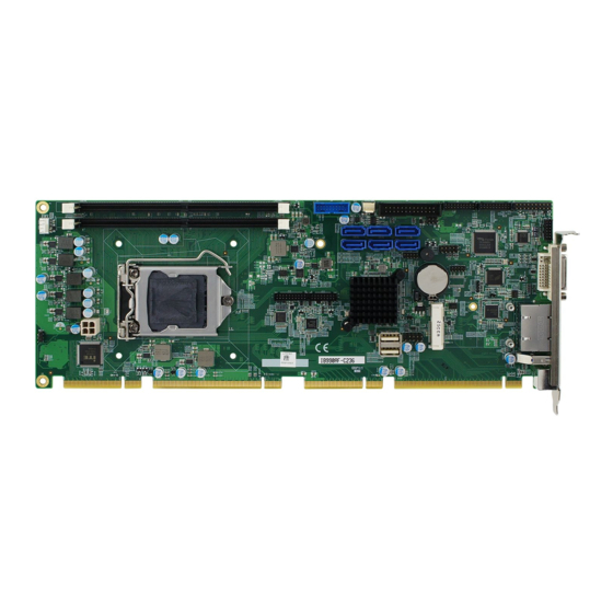
IB990 utilizes the dramatic increase in performance provided Intel’s latest cutting-edge technology. Measuring 338mm x122mm, the IB990 offers fast 6Gbps SATA support (up to 6 ports), USB3.0 (6 ports) and interfaces for two Gigabit Ethernet. Photo of IB990AF (for Q170) Features • Gen. Core™ i7/i5/i3 Processor, up ®... -
Page 11: Packing List
General Information Packing List Your IB990 package should include the items listed below. If any of the items below is missing, contact the distributor or dealer from whom you purchased the product. • The IB990 PICMG1.3 SHB x 1 • Disk x 1 (containing chipset drivers and flash memory utility) •... -
Page 12: Specifications
Specifications IB990AF IB990AF-C236 Product Name (for Q170) (for C236) Form Factor PICMG 1.3 SHB Express full size CPU card System • Windows 10 (64b) • Windows 8.1 (64b) / Embedded Industrial (64b) Operating System • Windows 7 Pro (32b/64b) •... - Page 13 General Information IB990AF IB990AF-C236 Product Name (for Q170) (for C236) System +5V, +3.3V, +12V, -12V & 5VSB Voltage Dimensions 338mm x 126mm RoHS Certification CE, FCC, LVD I/O Ports ® Intel PCH-H built-in SATA controller, SATAIII (3.0) 6 Gbps 6 ports:...
- Page 14 IB990AF IB990AF-C236 Product Name (for Q170) (for C236) Fintek F81846AD-I • COM1 (RS-232 /422 / 485) supports ring-in with power at 500 mA (selectable for 5V or 12V) *F81439 transceiver for jumper-less selection • COM2~ COM4 (RS-232 only) Super I/O Hardware Monitor (2 thermal inputs, 4 voltage monitor inputs &...
- Page 15 General Information IB990AF IB990AF-C236 Product Name (for Q170) (for C236) Environment Operation: 0 ~ 60 °C • Temperature Storage: -20 ~ 80 °C • Humidity Relative humidity: 0 ~ 90 %, non-condensing All specifications are subject to change without prior notice.
-
Page 16: Block Diagram
Block Diagram IB990 User’s Manual... -
Page 17: Overview
General Information Overview Top View Photo of IB990AF (for Q170) Photo of IB990AF-C236 (for C236) I/O View *The photos above are for reference only. Some minor components may differ. IB990 User’s Manual... -
Page 18: Dimensions
Dimensions REMOVE 186.56 338.58 14.5 13.45 Board diagram of IB990AF (for Q170) IB990 User’s Manual... -
Page 19: Chapter 2 Hardware Configuration
Chapter 2 Hardware Configuration This section provides information on jumper settings and connectors on the IB990 in order to set up a workable system. On top of that, you will also need to install crucial pieces such as the CPU and the memory before using the product. The topics covered are: •... -
Page 20: Essential Installations Before You Begin
Essential Installations Before You Begin Follow the instructions below to install the CPU and the memory. 2.1.1 Installing the CPU The IB990 board supports an LGA1151 Socket (shown below) for ® ® ® Intel Xeon E3 v5 family or Intel Gen. -
Page 21: Installing The Memory
Hardware Configuration 2.1.2 Installing the Memory The IB990 board supports two DDR4 memory socket for a maximum total memory of 32GB in DDR4 UDIMM memory type. To install the modules, locate the memory slot on the board and perform the following steps: Hold the module so that the key of the module aligned with that on the memory slot. -
Page 22: Setting The Jumpers
Setting the Jumpers Set up and configure your IB990 by using jumpers for various settings and features according to your needs and applications. Contact your supplier if you have doubts about the best configuration for your use. 2.2.1 How to Set Jumpers Jumpers are short-length conductors consisting of several metal pins with a non-conductive base mounted on the circuit board. -
Page 23: Jumper & Connector Locations On Ib990
Hardware Configuration Jumper & Connector Locations on IB990 REMOVE Board diagram of IB990AF (for Q170) IB990 User’s Manual... -
Page 24: Jumpers Quick Reference
Jumpers Quick Reference Function Jumper Name Page Clear CMOS Content JBAT1 COM1 RS-232 Power Setting PCIe (x16) Bifurcation Selection JP4, JP5 2.4.1 Clear CMOS Content (JBAT1) Function Pin closed Illustration Normal Clear CMOS IB990 User’s Manual... -
Page 25: Com1 Rs232 Power Setting (Jp1)
Hardware Configuration 2.4.2 COM1 RS232 Power Setting (JP1) Function Pin closed Illustration +12V IB990 User’s Manual... -
Page 26: Pcie (X16) Bifurcation Selection (Jp4 & Jp5)
2.4.3 PCIe (x16) Bifurcation Selection (JP4 & JP5) JP4: JP5: Function Pin closed Illustration JP4: Open 1 x PCIe (x16) JP5: Open JP4: Open 2 x PCIe (x8) JP5: Close JP4: Close 1 x PCIe (x8) 2 x PCIe (x4) JP5: Close IB990 User’s Manual... -
Page 27: Connectors Quick Reference
Hardware Configuration Connectors Quick Reference Function Connector Name Page COM1 and COM2 Serial Port COM3, COM4 Serial Port USB3.0 / USB 2.0 Connector USB2.0 Connectors Front Panel Function Connector External Audio Connector ATX 12V Power Connector Digital I/O 4 In/4 Out DVI-D Port Parallel Port VGA Port... -
Page 28: Com1 And Com2 Serial Port (J2)
2.5.1 COM1 and COM2 Serial Port (J2) Pin # Assigment Pin # Assigment DCD1 DSR1 RXD1 RTS1 TXD1 CTS1 DTR1 Ground DCD2 DSR2 RXD2 RTS2 TXD2 CTS2 DTR2 Ground IB990 User’s Manual... -
Page 29: Com3, Com4 Serial Port (J3)
Hardware Configuration 2.5.2 COM3, COM4 Serial Port (J3) Pin # Assigment Pin # Assigment DCD3 DSR3 RXD3 RTS3 TXD3 CTS3 DTR3 Ground DCD4 DSR4 RXD4 RTS4 TXD4 CTS4 DTR4 Ground IB990 User’s Manual... -
Page 30: Usb3.0/2.0 Connector (J5)
2.5.3 USB3.0/2.0 Connector (J5) Pin # Assigment Pin # Assigment VCC(900mA) P2_U2_D+ P1_SSRX- P2_U2_D- P1_SSRX+ P2_SSTX+ P1_SSTX- P2_SSTX- P1_SSTX+ P2_SSRX+ P1_U2_D- P2_SSRX- P1_U2_D+ VCC(900mA) IB990 User’s Manual... -
Page 31: Usb2.0 Connectors (J17)
Hardware Configuration 2.5.4 USB2.0 Connectors (J17) Pin # Assigment Pin # Assigment VCC (500mA) VCC (500mA) Ground Ground IB990 User’s Manual... -
Page 32: Front Panel Function Connector (J1)
2.5.5 Front Panel Function Connector (J1) Pin # Assigment Pin # Assigment Speaker Out Ground Ground Ground Ground Ground PWR_SW Ground HDD LED + HDD LED - IB990 User’s Manual... -
Page 33: External Audio Connector (J8)
Hardware Configuration 2.5.6 External Audio Connector (J8) J8 is a 12-pin header that is used to connect to the optional audio cable. Pin # Assigment Pin # Assigment Line out_L Line out_R JD_FRONT Ground LINE IN_L Line in_R JD_LINE IN Ground MIC-L MIC-R... -
Page 34: Atx 12V Power Connector (J16)
2.5.7 ATX 12V Power Connector (J16) J16 connector supplies the CPU operating voltage. Pin # Assigment Pin # Assigment Ground Ground +12V-IN +12V-IN 2.5.8 Digital I/O 4 In/4 Out (J9) Pin # Assigment Pin # Assigment OUT3 OUT1 OUT2 OUT0 IB990 User’s Manual... -
Page 35: Dvi-D Port (J13)
Hardware Configuration 2.5.9 DVI-D Port (J13) J13 is a 20-pin header used to connect to the optional DVI-D cable. Pin # Assigment Pin # Assigment TDC1_B TDC1#_B Ground Ground TLC_B TLC#_B Ground HPDET_B N.C. TDC2_B TDC2#_B Ground Ground TDC0_B TDC0#_B N.C. -
Page 36: Parallel Port (J6)
2.5.10 Parallel Port (J6) J6 is a 26-pin header used to connect to the optional printer port cable. Pin # Assigment Pin # Assigment Line printer strobe Auto Feed PD0, parallel data 0 Error PD1, parallel data 1 Initialize PD2, parallel data 2 Select PD3, parallel data 3 Ground... -
Page 37: Vga Port (J14)
Hardware Configuration 2.5.11 VGA Port (J14) J14 is a 16-pin header used to connect to the optional VGA port cable. Pin # Assigment Pin # Assigment CRT1_RED CRT1_GREEN Ground CRT1_BLUE CRT1_DDC_DATA_ISO Ground CRT1_HSYN_R Ground CRT1_VSYN_R Ground CRT1_DDC_CLK_ISO Ground IB990 User’s Manual... -
Page 38: Cpu Fan Power Connector (Cpu_Fan1)
2.5.12 CPU Fan Power Connector (CPU_FAN1) Pin # Assigment Pin # Assigment Ground Rotation detection +12V(1A) Control 2.5.13 System Fan1 Power Connector (SYS_FAN1) Pin # Assigment Pin # Assigment Ground Rotation detection +12V(1A) IB990 User’s Manual... -
Page 39: Chapter 3 Drivers Installation
Chapter 3 Drivers Installation This chapter introduces installation of the following drivers: • ® Intel Chipset Software Installation Utility • VGA Driver • HD Audio Driver • LAN Driver • ® Intel Management Engine Interface • ® Intel USB 3.0 Driver... -
Page 40: Introduction
Introduction This section describes the installation procedures for software and drivers. The software and drivers are included with the motherboard. If you find anything missing, please contact the distributor where you made the purchase. The contents of this section include the following: Note: After installing your Windows operating system, you must install first the Intel Chipset Software Installation Utility before proceeding with the drivers installation. -
Page 41: Intel ® Chipset Software Installation Utility
Driver Installation ® Intel Chipset Software Installation Utility ® The Intel Chipset drivers should be installed first before the software drivers to install INF files for Plug & Play function for Intel chipset components. Follow the instructions below to complete the installation. - Page 42 On the Readme File Information screen, click Install for installation. The driver has been completely installed. Click Finish to restart the computer and for changes to take effect. IB990 User’s Manual...
-
Page 43: Vga Driver Installation
Driver Installation VGA Driver Installation Insert the disk enclosed in the package with the board. Click Intel and then Intel(R) Skylake Chipset Drivers. Click Intel(R) HD Graphics Driver. IB990 User’s Manual... - Page 44 When the Welcome screen appears, click Next to continue. Click Yes to agree with the license agreement and continue the installation. IB990 User’s Manual...
- Page 45 Driver Installation On the Windows Security screen shown below, click Install to continue. The driver has been completely installed. Click Finish to restart the computer and for changes to take effect. IB990 User’s Manual...
-
Page 46: Hd Audio Driver Installation
HD Audio Driver Installation Insert the disk enclosed in the package with the board. Click Intel and then Intel(R) Skylake Chipset Drivers. Click Realtek High Definition Audio Driver. IB990 User’s Manual... - Page 47 Driver Installation On the Welcome screen of the InstallShield Wizard, click Next for installation. The installation is complete. Click Finish to restart the computer and for changes to take effect. IB990 User’s Manual...
-
Page 48: Lan Driver Installation
LAN Driver Installation Insert the disk enclosed in the package with the board. Click Intel and then Intel(R) Skylake Chipset Drivers. Click Intel(R) PRO LAN Network Drivers. IB990 User’s Manual... - Page 49 Driver Installation ® On the screen of Intel Network Connections, click Install Drivers and Software. When the Welcome screen appears, click Next. Click Next to to agree with the license agreement. IB990 User’s Manual...
- Page 50 On the Setup Options screen, click the checkbox to select the desired driver(s) for installation. Then click Next to continue. The wizard is ready for installation. Click Install. As the installation is complete, click Finish. Click Finish to restart the computer and for changes to take effect. IB990 User’s Manual...
-
Page 51: Intel ® Management Engine Interface
Driver Installation ® Intel Management Engine Interface Insert the disk enclosed in the package with the board. Click Intel and then Intel(R) Skylake Chipset Drivers. ® When the Welcome screen to the InstallShield Wizard for Intel Management Engine Components appears, click Next. Click Next to to agree with the license agreement. -
Page 52: Intel ® Usb 3.0 Driver
® Intel USB 3.0 Driver Insert the disk enclosed in the package with the board. Click Intel and then Intel(R) Skylake Chipset Drivers. Click Intel(R) USB 3.0 Drivers. IB990 User’s Manual... - Page 53 Driver Installation ® When the Welcome screen to the InstallShield Wizard for Intel USB 3.0 Host Controller Driver appears, click Next. Click Next to to agree with the license agreement. On the Readme File Information screen, click Next for installation. The driver has been successfully installed.
- Page 54 This page is intentionally left blank. IB990 User’s Manual...
-
Page 55: Chapter 4 Bios Setup
Chapter 4 BIOS Setup This chapter describes the different settings available in the AMI BIOS that comes with the board. The topics covered in this chapter are as follows: • Main Settings • Advanced Settings • Chipset Settings • Security Settings •... -
Page 56: Introduction
4.1 Introduction The BIOS (Basic Input/Output System) installed in the ROM of your ® computer system supports Intel processors. The BIOS provides critical low-level support for standard devices such as disk drives, serial ports and parallel ports. It also provides password protection as well as special support for detailed fine-tuning of the chipset controlling the entire system. - Page 57 BIOS Setup When you enter the BIOS Setup utility, the Main Menu screen will appear on the screen. The Main Menu allows you to select from various setup functions and exit choices. Warning: It is strongly recommended that you avoid making any changes to the chipset defaults.
-
Page 58: 4.3 Main Settings
4.3 Main Settings BIOS Setting Description System Date Sets the date. Use the <Tab> key to switch between the data elements. System Time Set the time. Use the <Tab> key to switch between the data elements. IB990 User’s Manual... -
Page 59: 4.4 Advanced Settings
BIOS Setup 4.4 Advanced Settings This section allows you to configure, improve your system and allows you to set up some system features according to your preference. IB990 User’s Manual... -
Page 60: Trusted Computing
4.4.1 Trusted Computing BIOS Setting Description Security Device Enables / Disables TPM support. O.S. will Support not show TPM. Reset of platform is required. Note: This feature is not supported on IB990AF-C236. IB990 User’s Manual... -
Page 61: Acpi Settings
BIOS Setup 4.4.2 ACPI Settings BIOS Setting Description Enable Hibernation Enables / Disables the system ability to hibernate (OS/S4 Sleep State). This option may be not effective with some OS. ACPI Sleep State Selects an ACPI sleep state where the system will enter when the Suspend button is pressed. -
Page 62: Amt Configuration
4.4.3 AMT Configuration BIOS Setting Description AMT Configuration Enables / Disables AMT configuration. Note: iAMT H/W is always enabled. This option just controls the BIOS extension execution. If enabled, this requires additional firmware in the SPI device. Unconfigure ME Unconfigures AMT/ME without password operation. -
Page 63: F81846 Super Io Configuration
BIOS Setup 4.4.4 F81846 Super IO Configuration BIOS Setting Description Serial Port Sets parameters of Serial Ports. Configuration Enables / Disables the serial port and select an optimal setting for the Super IO device. Parallel Port Set parameters of Parallel ports. Configuration (LPT/LPTE) IB990 User’s Manual... -
Page 64: Hardware Monitor
4.4.5 Hardware Monitor BIOS Setting Description CPU / System smart Enables / Disables the smart fan feature. fan control • Disabled (default) • 50 ℃ • 60 ℃ • 70 ℃ • 80 ℃ • 90 ℃ Temperatures/Voltages These fields are the parameters of the hardware monitoring function feature of the motherboard. -
Page 65: Cpu Configuration
BIOS Setup 4.4.6 CPU Configuration BIOS Setting Description Intel(R) Allows more than two frequency ranges to be SpeedStep(tm) supported. IB990 User’s Manual... -
Page 66: Sata Configuration
4.4.7 SATA Configuration BIOS Setting Description SATA Controller(s) Enables / Disables SATA devices. SATA Mode Determines how the SATA controller(s) Selection operate. • AHCI Mode • RAID Mode Hot Plug Designates this port as Hot Pluggable. External SATA Supports external SATA. Spin Up Device On an edge detection from 0 to 1, the PCH starts a COMRESET initialization sequence... -
Page 67: Csm Configuration
BIOS Setup 4.4.8 CSM Configuration BIOS Setting Description Network SATA Controls the execution of UEFI and legacy Controller(s) PXE OpROM. IB990 User’s Manual... -
Page 68: Usb Configuration
4.4.9 USB Configuration BIOS Setting Description Legacy USB Enables Legacy USB support. Support “Auto” disables legacy support if there is no USB device connected. “Disable” keeps USB devices available only for EFI applications. XHCI Hand-off This is a workaround for OSes without XHCI hand-off support. - Page 69 BIOS Setup BIOS Setting Description Device power-up The maximum time the device will take delay before it properly reports itself to the Host Controller. “Auto” uses default value for a Root port it is 100ms. But for a Hub port, the delay is taken from Hub descriptor.
-
Page 70: 4.5 Chipset Settings
4.5 Chipset Settings BIOS Setting Description System Agent (SA) System Agent (SA) parameters Configuration PCH-IO PCH parameters Configuration IB990 User’s Manual... -
Page 71: System Agent (Sa) Configuration
BIOS Setup 4.5.1 System Agent (SA) Configuration BIOS Setting Description VT-d Checks if VT-d function on MCH is supported. IB990 User’s Manual... -
Page 72: Graphics Configuration
4.5.2 Graphics Configuration BIOS Setting Description Skip Scanning of If enabled, it will not scan for external Gfx External Gfx Card Card on PEG and PCH PCIE ports. Primary Display Selects which of IGFX/PEG/PCI graphics device should be primary display, or selects SG for switchable Gfx. -
Page 73: Memory Configuration
BIOS Setup 4.5.3 Memory Configuration IB990 User’s Manual... -
Page 74: Pch-Io Configuration
4.5.4 PCH-IO Configuration This section allows you to configure the North Bridge Chipset. BIOS Setting Description PCH LAN Controller Enables / Disables the onboard NIC. Wake on LAN Enables / Disables the integrated LAN to wake the system. (The Wake On LAN cannot be disabled if ME is on at Sx state.) SLP_LAN# Low on Enables / Disables the SLP_LAN# Low on... -
Page 75: 4.6 Security Settings
BIOS Setup 4.6 Security Settings BIOS Setting Description Administrator Sets an administrator password for the setup Password utility. User Password Sets a user password. IB990 User’s Manual... -
Page 76: 4.7 Boot Settings
4.7 Boot Settings BIOS Setting Description Setup Prompt Number of seconds to wait for setup Timeout activation key. 65535(0xFFFF) means indefinite waiting. Bootup NumLock Selects the keyboard NumLock state. State Quiet Boot Enables / Disables Quiet Boot option. Fast Boot Enables / Disables boot with initialization of a minimal set of devices required to launch active boot option. -
Page 77: 4.8 Save & Exit Settings
BIOS Setup 4.8 Save & Exit Settings BIOS Setting Description Save Changes and Exits system setup after saving the changes. Exit Discard Changes Exits system setup without saving any and Exit changes. Save Changes and Resets the system after saving the changes. Reset Discard Changes Resets system setup without saving any... - Page 78 This page is intentionally left blank. IB990 User’s Manual...
-
Page 79: Appendix
Appendix This section provides the mapping addresses of peripheral devices and the sample code of watchdog timer configuration. - Page 80 I/O Port Address Map Each peripheral device in the system is assigned a set of I/O port addresses which also becomes the identity of the device. The following table lists the I/O port addresses used. Address Device Description 0000h-0CF7h PCI Express Root Complex 0040h-0043h System timer 0050h-0053h...
- Page 81 Appendix Interrupt Request Lines (IRQ) Peripheral devices use interrupt request lines to notify CPU for the service required. The following table shows the IRQ used by the devices on board. Level Function IRQ0 System Timer IRQ3 Serial Port #2 IRQ4 Serial Port #1 IRQ5 Serial Port #3...
- Page 82 Watchdog Timer Configuration The Watchdog Timer (WDT) is used to generate a variety of output signals after a user programmable count. The WDT is suitable for use in the prevention of system lock-up, such as when software becomes trapped in a deadlock. Under these sorts of circumstances, the timer will count to zero and the selected outputs will be driven.
- Page 83 Appendix DisableWDT(); return 0; //--------------------------------------------------------------------------- void EnableWDT(int interval) unsigned char bBuf; bBuf = Get_F81866_Reg(0x2B); bBuf &= (~0x20); Set_F81866_Reg(0x2B, bBuf); //Enable WDTO Set_F81866_LD(0x07); //switch to logic device 7 Set_F81866_Reg(0x30, 0x01); //enable timer bBuf = Get_F81866_Reg(0xF5); bBuf &= (~0x0F); bBuf |= 0x52; Set_F81866_Reg(0xF5, bBuf);...
- Page 84 //--------------------------------------------------------------------------- unsigned int Init_F81866(void) unsigned int result; unsigned char ucDid; F81866_BASE = 0x4E; result = F81866_BASE; ucDid = Get_F81866_Reg(0x20); if (ucDid == 0x07) //Fintek 81866 goto Init_Finish; F81866_BASE = 0x2E; result = F81866_BASE; ucDid = Get_F81866_Reg(0x20); if (ucDid == 0x07) //Fintek 81866 goto Init_Finish;...
- Page 85 Appendix //--------------------------------------------------------------------------- #ifndef __F81866_H #define __F81866_H //--------------------------------------------------------------------------- #define F81866_INDEX_PORT (F81866_BASE) #define F81866_DATA_PORT (F81866_BASE+1) //--------------------------------------------------------------------------- #define F81866_REG_LD 0x07 //--------------------------------------------------------------------------- #define F81866_UNLOCK 0x87 #define F81866_LOCK 0xAA //--------------------------------------------------------------------------- unsigned int Init_F81866(void); void Set_F81866_LD( unsigned char); void Set_F81866_Reg( unsigned char, unsigned char); unsigned char Get_F81866_Reg( unsigned char); //--------------------------------------------------------------------------- #endif //__F81866_H...
Need help?
Do you have a question about the IB990AF and is the answer not in the manual?
Questions and answers