
Related Manuals for IBASE Technology 11th Gen Intel Core U-Series


Summary of Contents for IBASE Technology 11th Gen Intel Core U-Series
- Page 1 SI-654-N 11th Gen Intel® Core™ U-Series Processor Fanless Signage Player with Four HDMI 2.0 User’s Manual Version 1.0 (November 2021)
- Page 2 No part of this publication may be reproduced, copied, stored in a retrieval system, translated into any language or transmitted in any form or by any means, electronic, mechanical, photocopying, or otherwise, without the prior written consent of IBASE Technology, Inc. (hereinafter referred to as “IBASE”).
- Page 3 Compliance In a domestic environment, this product may cause radio interference in which case users may be required to take adequate measures. This product has been tested and found to comply with the limits for a Class B device, pursuant to Part 15 of the FCC Rules. These limits are designed to provide reasonable protection against harmful interference in a residential installation.
- Page 4 Important Safety Information Carefully read the precautions before using the device. Environmental conditions: Lay the device horizontally on a stable and solid surface in case the device may fall, causing serious damage. Leave plenty of space around the device and do not block the openings for ventilation.
- Page 5 CAUTION There is danger of explosion if internal lithium-ion battery is replaced by an incorrect type. Replace only with the same or equivalent type recommended by the manufacturer. Dispose of used batteries according to the manufacturer’s instructions. Warranty Policy IBASE standard products: 24-month (2-year) warranty from the date of shipment.
-
Page 6: Table Of Contents
Table of Contents Chapter 1 General Information ............... 1 Introduction ....................2 Features ....................2 Packing List ....................3 Specifications ................... 3 Product View .................... 5 Dimensions ....................7 Chapter 2 ... - Page 7 Chapter 4 BIOS Setup ................32 Introduction ..................... 33 BIOS Setup ..................... 33 Main Settings ..................34 Advanced Settings .................. 34 Chipset Settings ..................48 Security Settings ..................53 ...
-
Page 9: Chapter 1 General Information
Chapter 1 General Information The information provided in this chapter includes: Features Packing List Accessories Specifications Product View Dimensions... -
Page 10: Introduction
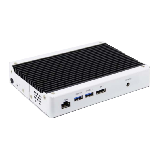
1.1 Introduction The SI-654-N is a fanless 8K digital signage player powered by Intel's latest 11th Gen Intel® Core™ U-Series processors (formerly Tiger Lake) manufactured with Intel's 10nm SuperFin transistor that achieves up to 17.5% performance uplift and significantly higher clock speeds at lower power compared to the original 10nm. Measuring 200 x 139 x 41 mm, the SI-654-N can be easily installed in space- constraint environments. -
Page 11: Packing List
General Information 1.3 Packing List Your product package should include the items listed below. If any of the items below is missing, contact the distributor or the dealer from whom you purchased the product. SI-654-N Digital Signage Player Power Adaptor ... - Page 12 Watchdog Watchdog Timer: 256 segments, 0, 1, 2…255 (sec/min) Power +12V DC Requirement Construction Aluminum + SGCC Chassis Color Black & White Power Supply 84W power adaptor Mounting Standard system bracket 200.8mm(W) x 139.3mm(D) x 41.2mm(H) Dimensions (W x H x D) 7.90”(W) x 5.48”(D) x 1.62”(H) Certificate CE, FCC Class B, UKCA, UKCA, cULus &...
-
Page 13: Product View
General Information 1.5 Product View Front View Function Function Line-Out Jack USB 2.0 Connector COM1 RJ45 Connector DC-In Jack (+12V USB 3.1 Connectors Rear View Function Function HDD Activity LED EDID Clear Button Power Button HDMI 2.0 Connector Power LED LAN ports SI-654 User’s Manual... - Page 14 Oblique View SI-654 User’s Manual...
-
Page 15: Dimensions
General Information 1.6 Dimensions Unit: mm SI-654 User’s Manual... -
Page 16: Hardware Installation & Motherboard Information
Chapter 2 Hardware Installation & Motherboard Information The information provided in this chapter includes: Installation /Replacement Jumpers and Connectors ... -
Page 17: Installation / Replacement
Hardware Configuration 2.1 Installation / Replacement The following pictures show how to disassemble the SI-654-N. 1. Remove the cover plate by releasing the five (5) screws shown below. 2. Remove the side plate by releasing the two (2) screws shown below. SI-654 User’s Manual... - Page 18 3. Remove the I/O connector cover plates by releasing the five (5) screws shown below. 4. Separate the system board from the base heat sink by releasing the six (6) screws shown below. SI-654 User’s Manual...
-
Page 19: Memory
Hardware Configuration 2.1.1 Memory To install the modules, locate the memory slot on the motherboard. The MBD654 series supports two DDR4 memory sockets. To install the modules, locate the memory slot on the board and perform the following steps: 1. Align the key of the memory module with that on the memory slot and insert the module slantwise. -
Page 20: Mini-Pcie & M.2 Cards
2.1.2 Mini-PCIe & M.2 Cards 1. Locate the M.2 slot inside the device. 2. Align the key of the M.2 card to the interface, and insert the card slantwise. 3. Fix the M.2 card with an M3 screw. M.2: 2.1.3 WiFi / 3G / 4G Antenna Installation Thread the WiFi / 3G / 4G antenna extension cable through an antenna hole of the front I/O cover and fasten the antenna as shown below. -
Page 21: Hdmi Cable Holder Installation
Hardware Configuration 2.1.4 HDMI Cable Holder Installation The SI-654 is provided with an HDMI cable holder that can be used to hold the HDMI cables to prevent loose connections. Use the two screws that come with the holder to adjust the cable grip and tighten the holder into place. 2.1.5 DC Power Plug Holder Installation The SI-654 is also provided with a DC power plug holder to keep the power... -
Page 22: Setting The Jumpers
2.2 Setting the Jumpers Set up and configure your SI-654-N by using jumpers for various settings and features according to your needs and applications. Contact your supplier if you have doubts about the best configuration for your use. 2.3.1 How to Set Jumpers Jumpers are short-length conductors consisting of several metal pins with a non-conductive base mounted on the circuit board. -
Page 23: Jumper & Connector Locations
Hardware Configuration 2.3 Jumper & Connector Locations Motherboard: MBD654 SI-654 User’s Manual... - Page 24 2.4.1 JP1: Clear RTC Function Pin closed Normal (Default) Clear RTC 2.4.2 JP2: Clear CMOS Function Pin closed Normal (Default) Clear CMOS 2.4.3 JP4: AT/ATX Mode Selection Function Pin closed 2.4.4 JP3: Flash Descriptor Security Override (Factory use only) Function Pin Setting Disabled Open...
-
Page 25: Cn6: Com1 (Rj45) Port
Hardware Configuration 2.4.6 CN6: COM1 (RJ45) Port: Signal Name Pin Pin Function RTS, Request to Send Data Terminal Ready TXD, Transmit Data GND, Ground GND, Ground RXD, Receive Data DSR, Data Set Ready CTS, Clear to Send 2.4.7 J2: SPI Flash Header 2.4.8 J3: Battery Header SI-654 User’s Manual... -
Page 26: J4: Espi Debug Header
2.4.9 J4: ESPI Debug Header 2.4.10 J6: MCU Header 2.4.11 J7: M.2 E-Key SI-654 User’s Manual... -
Page 27: J8: Front Panel
Hardware Configuration 2.4.12 J8: Front Panel Pin Signal Name Pin Signal Name Power BTN Power BTN HDD LED+ HDD LED- Reset BTN Reset BTN Power LED+ Power LED- 2.4.13 J9: M.2 B-Key SI-654 User’s Manual... -
Page 28: J10: Cpld Debug Header
2.4.14 J10: CPLD Debug Header 2.4.15 J12: M.2 M-Key SI-654 User’s Manual... -
Page 29: Chapter 3 Driver Installation
Chapter 3 Driver Installation The information provided in this chapter includes: Intel® Chipset Software Installation Utility HD Audio Driver Installation LAN Driver Installation Intel® Management Engine Components Drivers Installation... -
Page 30: Introduction
3.1 Introduction This section describes the installation procedures for software drivers. The software drivers are available on IBASE website www.ibase.com.tw. Register as a member of our website to download all the necessary drivers and extract for installation. Note: After installing your Windows operating system, you must install the Intel ®... - Page 31 Driver Installation 2. Click Intel(R) Chipset Software Installation Utility. 3. When the Welcome screen to the Intel ® Chipset Device Software appears, click Next to continue. 4. Accept the software license agreement. 5. On the Readme File Information screen, click Install. 6.
-
Page 32: Hd Audio Driver Installation
3.3 HD Audio Driver Installation 1. Insert the disk enclosed in the package with the board. Click Intel on the left pane and then Intel(R) TigerLake-U Chipset Drivers on the right pane. 2. Click Realtek High Definition Audio Driver. SI-654 User’s Manual... - Page 33 Driver Installation 3. On the Welcome screen of the InstallShield Wizard, click Next. 4. When the driver is completely installed, click Finish. SI-654 User’s Manual...
-
Page 34: Lan Driver Installation
3.4 LAN Driver Installation 1. Insert the disk enclosed in the package with the board. Click Intel on the left pane and then Intel(R) TigerLake-U Chipset Drivers on the right pane. 2. Click Intel(R) PRO LAN Network Drivers.. SI-654 User’s Manual... - Page 35 Driver Installation 3. On the next screen, click Install Drivers and Software. 4. When the Welcome screen appears, click Next. 5. Accept the license agreement and click Next. 6. On the Setup Options screen, select the desired features you want installed.
-
Page 36: Intel Management Engine Components Drivers Installation
® 3.5 Intel Management Engine Components Drivers Installation 1. Insert the disk enclosed in the package with the board. Click Intel on the left pane and then Intel(R) TigerLake-U Chipset Drivers on the right pane. 2. Click Intel(R) ME 15.x Drivers. SI-654 User’s Manual... - Page 37 Driver Installation 3. When the Welcome screen appears, click Next. 4. Accept the license agreement and click Next. 5. On the Destination Folder screen, click Next. 6. After Intel Management Engine Components have been successfully installed, click Finish. SI-654 User’s Manual...
-
Page 38: Intel Thunderbolt Drivers Installation
3.6 Intel Thunderbolt Drivers Installation 1. Insert the disk enclosed in the package with the board. Click Intel on the left pane and then Intel(R) TigerLake-U Chipset Drivers on the right pane. 2. Click Intel(R) Thunderbolt Drivers. SI-654 User’s Manual... - Page 39 Driver Installation 3. In the next screen, accept the license agreement and click Next. 4. When the drivers have been successfully installed, click Restart. SI-654 User’s Manual...
-
Page 40: Chapter 4 Bios Setup
Chapter 4 BIOS Setup This chapter describes the different settings available in the AMI BIOS that comes with the board. The topics covered in this chapter are as follows: Main Settings Advanced Settings Chipset Settings Security Settings ... -
Page 41: Introduction
BIOS Setup 4.1 Introduction The BIOS (Basic Input/Output System) installed in the ROM of your computer system supports Intel® processors. The BIOS provides critical low-level support for standard devices such as disk drives, serial ports and parallel ports. It also provides password protection as well as special support for detailed fine-tuning of the chipset controlling the entire system. -
Page 42: Main Settings
4.3 Main Settings BIOS Setting Description Sets the date. System Date Use the <Tab> key to switch between the data elements. Set the time. System Time Use the <Tab> key to switch between the data elements. 4.4 Advanced Settings This section allows you to configure, improve your system and allows you to set up some system features according to your preference. - Page 43 BIOS Setup 4.4.1 Connectivity Configuration BIOS Setting Description This option configures connectivity. Auto Detection means that if Discrete solution is CNVi Mode discovered it will be enabled by default. Otherwise Integrated solution (CNV1) will be enabled. Disable Integrated disables Integrated Solution. This is a test option whch allows configuration of UART MfUart1 type type for WiFi side band communication.
- Page 44 4.4.2 CPU Configuration BIOS Setting Description When enabled, a VMM can utilize the Intel (VMX) Virtualization additional hardware capabilities provided by Technology Vanderpool Technology. Number of cores to enable in each processor Active Procesor Cores package. Enable or Disable Hyper-Threading Hyper-Threading Technology Enable/Disable AES (Advanced Encryption...
- Page 45 BIOS Setup 4.4.3 Power & Performance BIOS Setting Description CPU – Power CPU power management control options. Management Control Allows more than two frequency ranges to be Intel(R) SpeedStep(tm) supported Enable/Disable Intel(R) Speed Shift Intel(R) Speed Shift Technology support. Enabling will expose the Technology CPPC V2 interface to allow for hardware controlled P-states.
- Page 46 4.4.4 PCH-FW Configuration SI-654 User’s Manual...
- Page 47 BIOS Setup 4.4.5 ACPI Settings BIOS Setting Description Enables / Disables BIOS support for security Security Device device. OS will not show security device. TCG Support EFI protocol and INTIA interface will not be available. SHA-1 PCR Bank Options: Enable / Disable Schedule an operation for the security device.
- Page 48 2.0 devices. If not found, TPM 1.2 devices will be enumerated. SI-654 User’s Manual...
- Page 49 BIOS Setup 4.4.6 Trusted Computing BIOS Setting Description Enables / Disables BIOS support for security device. OS will not show security device. TCG Security Device Support EFI protocol and INTIA interface will not be available. SHA-1 PCR Bank Options: Enable / Disable SHA256 PCR Bank Options: Enable / Disable Schedule an operation for the security device.
- Page 50 4.4.7 ACPI Settings BIOS Setting Description Enables / Disables system ability to hibernate Enable Hibernation (OS/S4 Sleep State). This option may not be effective with some operating systems. SI-654 User’s Manual...
- Page 51 BIOS Setup 4.4.8 iSmart Controller BIOS Setting Description Power-On after Power Enables / Disables the system to be turned on failure automatically after a power failure. PWR Resume Delay Enables / Disables Power on resume delay. Temperature Guardian Options: Disable / Enable Sets up the hour / minute for system powe-on.
- Page 52 4.4.9 F81804 Super IO Configuration BIOS Setting Description Serial Port 1 Configuration Sets parameters of Serial Port 1 (COMA). Serial Port Enable / Disable the serial port. Select an optimal setting for the Super IO Change Settings device. SI-654 User’s Manual...
- Page 53 BIOS Setup 4.4.10 Hardware Monitor BIOS Setting Description These fields are the parameters of the hardware monitoring function feature of the Temperatures / Voltages motherboard. The values are read-only values as monitored by the system and show the PC health status. 4.4.11 AMI Graphic Output Protocol Policy SI-654 User’s Manual...
- Page 54 4.4.12 USB Configuration BIOS Setting Description Enable: Enables Ledacy USB Support. Auto: Disables legacy support if no USB Legacy USB Support devices are connected. Disable: Keeps USB devices available only for EFI applications. This is a workaround for OSes without XHCI XHCI Hand-off hand-off support.
- Page 55 BIOS Setup 4.4.13 Network Stack Configuration BIOS Setting Description Network Stack Enables / Disables UEFI Network Stack. 4.4.14 NVMe Configuration SI-654 User’s Manual...
-
Page 56: Chipset Settings
4.5 Chipset Settings BIOS Setting Description System Agent (SA) Configuration System Agent (SA) parameters PCH-IO Configuration PCH parameters SI-654 User’s Manual... - Page 57 BIOS Setup 4.5.1 System Agent (SA) Configuration BIOS Setting Description System Agent (SA) System Agent (SA) Parameters Configuration Graphics Configuration Configures the graphics settings. VT-d Checks if VT-d function on MCH is supported. SI-654 User’s Manual...
- Page 58 4.5.1.1. Graphics Configuration BIOS Setting Description Graphics Turbo Graphics tubo IMON current values supported (14-31) IMON Current GTT Size Sets the GTT size as 2 MB, 4 MB, or 8 MB. Sets the aperture size as 128 MB, 256 MB, 512 MB, 1024 MB or 2048 MB.
- Page 59 BIOS Setup 4.5.2 PCH-IO Configuration BIOS Setting Description SATA and RST Configures SATA devices. Configuration PCH LAN Enables / Disables the onboard NIC. Controller Wake on LAN Enables / Disables the integrated LAN to wake up the Enable system. SI-654 User’s Manual...
- Page 60 4.5.2.1. SATA and RST Configuration: BIOS Setting Description SATA Enables / Disables the SATA device. Controller(s) SATA Mode Determines how SATA controller(s) operate. Selection Options: AHCI / Intel RST Premium Serial ATA Enables / Disables serial ports. Ports SATA Ports Hot Enables / Disables SATA Ports HotPlug.
-
Page 61: Security Settings
BIOS Setup 4.6 Security Settings BIOS Setting Description Administrator Sets an administrator password for the setup utility. Password User Password Sets a user password. Secure Boot Configures Secure Boot. SI-654 User’s Manual... - Page 62 4.6.1 Secure Boot BIOS Setting Description Secure Boot feature is Active if Secure Boot is enabled. Secure Boot Platform Key (PK) Is enrolled and the system is in User mode. The mode change requires platform reset. Secure Boot mode options: Standard or Custom.
-
Page 63: Boot Settings
BIOS Setup 4.7 Boot Settings BIOS Setting Description Setup Prompt Number of seconds to wait for setup activation key. Timeout 65535(0xFFFF) means indefinite waiting. Bootup Selects the keyboard NumLock state. NumLock State Quiet Boot Enables / Disables Quiet Boot option. Boot Option Sets the system boot order. -
Page 64: Save & Exit Settings
4.8 Save & Exit Settings BIOS Setting Description Save Changes and Exits system setup after saving the changes. Exit Discard Changes Exits system setup without saving any changes. and Exit Save Changes and Resets the system after saving the changes. Reset Discard Changes Resets system setup without saving any changes. -
Page 65: Appendix
Appendix This section provides the mapping addresses of peripheral devices and the sample code of watchdog timer configuration. I/O Port Address Map Interrupt Request Lines (IRQ) -
Page 66: I/O Port Address Map
A. I/O Port Address Map Each peripheral device in the system is assigned a set of I/O port addresses which also becomes the identity of the device. The following table lists the I/O port addresses used. Address Device Description 0x00000A00-0x00000A0F Motherboard resources 0x00000A10-0x00000A1F Motherboard resources... - Page 67 Appendix Address Device Description 0x00000000-0x00000CF7 PCI Express Root Complex 0x00000020-0x00000021 Programmable interrupt controller 0x00000024-0x00000025 Programmable interrupt controller 0x00000028-0x00000029 Programmable interrupt controller 0x0000002C-0x0000002D Programmable interrupt controller 0x0000002E-0x0000002F Motherboard Resources 0x00000030-0x00000031 Programmable interrupt controller 0x00000034-0x00000035 Programmable interrupt controller 0x00000038-0x00000039 Programmable interrupt controller 0x0000003C-0x0000003D Programmable interrupt controller 0x00000040-0x00000043...
- Page 68 0x00000A20-0x00000A2F Motherboard resources 0x00000D00-0x0000FFFF PCI Express Root Complex 0x0000164E-0x0000164F Motherboard resources 0x00001800-0x000018FE Motherboard resources 0x00001854-0x00001857 Motherboard resources 0x00002000-0x000020FE Motherboard resources 0x00004000-0x0000403F Intel(R) Iris (R) Xe Graphics 0x00004060-0x0000407F Standard SATA AHCI Controller 0x00004080-0x00004083 Standard SATA AHCI Controller 0x00004090-0x00004097 Standard SATA AHCI Controller 0x00004060-0x0000407F Standard SATA AHCI Controller 0x0000EFA0-0x0000EFBF...
-
Page 69: Interrupt Request Lines (Irq)
Appendix B. Interrupt Request Lines (IRQ) Peripheral devices use interrupt request lines to notify CPU for the service required. The following table shows the IRQ used by the devices on board. Level Function IRQ 0 System timer IRQ 1 Standard PS/2 Keyboard IRQ 3 Communications Port (COM2) IRQ 4... -
Page 70: Collage Mode Display Setting Configurations
C. Collage Mode Display Setting Configurations Driver Name and Version : 27.20.100.8729 OS and Version : (for example : Windows 10 64bit Version 20H2 (OS Build 19042.1165) vBIOS/GOP Version and Type : 17.0.1049 Resolution Display mode 4K 60GHz 4K 30GHz Full HD 60GHz 1 x 2...
Need help?
Do you have a question about the 11th Gen Intel Core U-Series and is the answer not in the manual?
Questions and answers