
Related Manuals for IBASE Technology IB835F


Summary of Contents for IBASE Technology IB835F
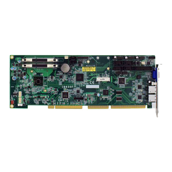
- Page 1 IB835F Intel Cedar Trail + NM10 ® PICMG1.0 Full Size CPU Card USER’S MANUAL Version 1.0...
- Page 2 Intel and Cedarview are registered trademarks of Intel Corporation. Microsoft Windows is a registered trademark of Microsoft Corporation. Winbond is a registered trademark of Winbond Electronics Corporation. All other product names or trademarks are properties of their respective owners. IB835F User’s Manual...
-
Page 3: Table Of Contents
Table of Contents Introduction ............1 Checklist ................2 IB835F Specifications ............3 Board Dimensions .............. 4 Installations ............5 Installing the Memory............6 Setting the Jumpers............. 7 Connectors on IB835F............12 BIOS Setup ............23 BIOS Introduction ............24 BIOS Setup............... 24 Advanced Settings ............ - Page 4 This page is intentionally left blank. IB835F User’s Manual...
-
Page 5: Introduction
INTRODUCTION Introduction IB835F is a PICMG1.0 Full Size CPU Card that comes with the Intel Atom D2550 processor running 1.86GHz and with a 1MB L2 cache. The ® board is based on the Intel CG82NM10 PCH chipset and supports two SODIMM with a maximum memory capacity of 4GB. -
Page 6: Checklist
INTRODUCTION Checklist Your IB835F package should include the items listed below. • The IB835F PICMG1.0 Full Size CPU Card • This User’s Manual • I/O bracket • 1 DVD containing chipset drivers and flash memory utility IB835F User’s Manual... -
Page 7: Ib835F Specifications
+5V, +3.3V, +12V, -12V & 5VSB RoHS Expansion Slots Mini PCIe socket x1@ component side Certification CE/ FCC Class B / LVD OS support Windows 8/8.1 Windows 7 (32-bit only) Linux (Fedora ; Ubuntu) Board Size 338mm x 122mm (13.31” x 4.8”) IB835F User’s Manual... -
Page 8: Board Dimensions
INTRODUCTION Board Dimensions IB835F User’s Manual... -
Page 9: Installations
INSTALLATIONS Installations This section provides information on how to use the jumpers and connectors on the IB835F in order to set up a workable system. The topics covered are: Installing the Memory ................6 Setting the Jumpers ................7 Connectors on IB835F ............... 12... -
Page 10: Installing The Memory
INSTALLATIONS Installing the Memory The IB835F board supports two DDR3-1066 memory modules. Installing and Removing Memory Modules To install the DDR3 modules, locate the memory slot on the board and perform the following steps: 1. Hold the DDR3 module so that the key of the DDR3 module aligned with that on the memory slot. -
Page 11: Setting The Jumpers
INSTALLATIONS Setting the Jumpers Jumpers are used on IB835F to select various settings and features according to your needs and applications. Contact your supplier if you have doubts about the best configuration for your needs. The following lists the connectors on IB835F and their respective functions. -
Page 12: Jumper Locations On Ib835F
INSTALLATIONS Jumper Locations on IB835F Jumper Locations on IB835F ............Page JP1: COM1 RS232 RI/+5V/+12V Power Setting ....... 10 JP2: COM2 RS232 RI/+5V/+12V Power Setting ....... 10 JP3: Clear CMOS Setting ..............10 JP4: LCD Panel Power Selection ............11 JP6: LCD BackLight Control Output Level ........ -
Page 13: Jp1: Com1 Rs232 Ri/+5V/+12V Power Setting
JP1: COM1 RS232 RI/+5V/+12V Power Setting Setting Function Pin 1-2 +12V Short/Closed Pin 3-4 Short/Closed Pin 5-6 Short/Closed *COM1: J5 JP2: COM2 RS232 RI/+5V/+12V Power Setting Setting Function Pin 1-2 +12V Short/Closed Pin 3-4 Short/Closed Pin 5-6 Short/Closed *COM2: J8 IB835F User’s Manual... -
Page 14: Jp3: Clear Cmos Setting
INSTALLATIONS JP3: Clear CMOS Setting Setting Normal* Clear CMOS JP4: LCD Panel Power Selection LCD Panel Power +3.3V* JP6: LCD BackLight Control Output Level Setting +3.3V* IB835F User’s Manual... -
Page 15: Jp7: Lvds Function Mode Setting
INSTALLATIONS JP7: LVDS function mode Setting Setting *Default IB835F User’s Manual... -
Page 16: Connectors On Ib835F
INSTALLATIONS Connectors on IB835F The connectors on IB835F allows you to connect external devices such as keyboard, floppy disk drives, hard disk drives, printers, etc. The following table lists the connectors on IB835F and their respective functions. Connector Locations on IB835F ............13 CN1, CN5: SATA 2.0 Connectors ............. -
Page 17: Connector Locations On Ib835F
INSTALLATIONS Connector Locations on IB835F IB835F User’s Manual... -
Page 18: Cn1, Cn5: Sata 2.0 Connectors
INSTALLATIONS CN1, CN5: SATA 2.0 Connectors CN2, CN3, CN4: USB 2.0 Connectors Signal Name Pin # Pin # Signal Name Ground Ground CN6: Mini PCIE Connector IB835F User’s Manual... -
Page 19: Cn7: Db-15 Vga Connector
CN9, CN10: Gigabit LAN (Intel I211AT) CN11: PS/2 Keyboard & Mouse Signal Name Signal Name Keyboard data N.C. Mouse data Mouse clock N.C. N.C. N.C. N.C. Keyboard clock N.C. CN12: CFast (Share with SATA port CN5 via SATA switch) IB835F User’s Manual... -
Page 20: J1: External Audio Connector
JD LINE IN Ground MIC-L MIC-R JD MIC1 Ground J2: Front Panel Function Connector Signal Name Pin # Pin # Signal Name Speaker Out Ground Ground Ground Ground Ground PWR_SW Ground Ground HDD LED + HDD LED - IB835F User’s Manual... -
Page 21: J3: Spi Flash Connector (Factory Use Only)
Pin # Pin # Signal Name DCD, Data carrier detect RXD, Receive data TXD, Transmit data DTR, Data terminal ready GND, ground DSR, Data set ready RTS, Request to send CTS, Clear to send RI, Ring indicator Not Used IB835F User’s Manual... -
Page 22: J8: Com2 Rs232/422/485
INSTALLATIONS J8: COM2 RS232/422/485 Pin # Signal Name RS-232 R2-422 RS-485 DATA- DATA+ Ground Ground Ground * Pin 9 supports RI/+5V/+12V function. IB835F User’s Manual... -
Page 23: J6: Parallel Port
PD3, parallel data 3 Ground PD4, parallel data 4 Ground PD5, parallel data 5 Ground PD6, parallel data 6 Ground PD7, parallel data 7 Ground ACK, acknowledge Ground Busy Ground Paper empty Ground Select Ground J10: Debug 80 Port IB835F User’s Manual... -
Page 24: J11: Digital I/O
Signal Name Pin # Pin # Signal Name OUT3 OUT1 OUT2 OUT0 J12, J14: CH1, CH2: LVDS Connectors Signal Name Pin # Pin # Signal Name LD0+ LD0- LD1+ LD1- LD2+ LD2- CLK+ CLK- LD3+ LD3- LCD_PWR LCD_PWR IB835F User’s Manual... -
Page 25: J15: External Atx Power Connector
Pin # Signal Name Ground PS-ON (soft on/off) 5VSB (Standby +5V) J16: LCD Backlight Connector Pin # Signal Name +12V Backlight Enable Brightness Control Ground CPU_FAN1: CPU Fan Power Connector Pin # Signal Name Ground +12V Control IB835F User’s Manual... -
Page 26: Sys_Fan1: System Fan Power Connector
INSTALLATIONS SYS_FAN1: System Fan Power Connector Pin # Signal Name Ground +12V IB835F User’s Manual... -
Page 27: Bios Setup
The topics covered in this chapter are as follows: BIOS Introduction ................24 BIOS Setup ..................24 Advanced Settings ................25 Chipset Settings ................. 34 Boot Settings ..................... 37 Security Settings ................39 Save & Exit Settings ................40 IB835F User’s Manual... -
Page 28: Bios Introduction
These defaults have been carefully chosen by both AMI and your system manufacturer to provide the absolute maximum performance and reliability. Changing the defaults could cause the system to become unstable and crash in some cases. IB835F User’s Manual... -
Page 29: Advanced Settings
F3: Optimized Default ► PPM Configuration F4: Save ESC: Exit Launch PXE OpROM Enable or Disable Boot Option for Legacy Network Devices. Launch Storage OpROM Enable or Disable Boot Option for Legacy Mass Storage Devices with Option ROM. IB835F User’s Manual... -
Page 30: Pci Subsystem Settings
Value to be programmed into PCI Latency Timer Register. VGA Palette Snoop Enables or Disables VGA Palette Registers Snooping. PERR# Generation Enables or Disables PCI Device to Generate PERR#. SERR# Generation Enables or Disables PCI Device to Generate SERR#. IB835F User’s Manual... -
Page 31: Acpi Settings
Enable ACPI Auto Configuration Disabled → ← Select Screen ↑↓ Select Item Enter: Select Change Field F1: General Help F2: Previous Values F3: Optimized Default F4: Save ESC: Exit Enabled ACPI Auto Configuration Enables or Disables BIOS ACPI Auto Configuration. IB835F User’s Manual... -
Page 32: Wake On Ring
F4: Save ESC: Exit Wake on Ring The options are Disabled and Enabled. Wake on PCIE PME The options are Disabled and Enabled. Remarks: If Wake on LAN is to be supported, this option should be enabled. IB835F User’s Manual... -
Page 33: Cpu Configuration
Execute Disable Bit XD can prevent certain classes of malicious buffer overflow attacks when combined with a supporting OS (Windows Server 2003 SP1, Windows XP SP2, SuSE Linux 9.2, Re33dHat Enterprise 3 Update 3.) IB835F User’s Manual... -
Page 34: Sata Configuration
SATA Controller(s) Enabled Change Field F1: General Help Configure SATA as F2: Previous Values F3: Optimized Default F4: Save ESC: Exit SATA Controller(s) Enable / Disable Serial ATA Controller. Configure SATA as (1) IDE Mode. (2) AHCI Mode. IB835F User’s Manual... -
Page 35: Usb Configuration
Maximum time the device will take before it properly reports itself to the Host Controller. ‘Auto’ uses default value: for a Root port it is 100ms, for a Hub port the delay is taken from Hub descriptor. IB835F User’s Manual... - Page 36 The options are : Level-1 (Maximum) , Level-2 , Level-3 , Level-4 , Level-5 , Level-6 , Level-7 , Level-8 (~0V). Backlight Output Mode This provides PWM duty-cycle output or DAC voltage output. PWM Frequency Selection This provides 4 frequency selection. IB835F User’s Manual...
-
Page 37: Ppm Configuration
Aptio Setup Utility Advanced Main Chipset Boot Security Save & Exit PPM Configuration → ← Select Screen EIST Enabled ↑↓ Select Item Enter: Select Change Field F1: General Help F2: Previous Values F3: Optimized Default F4: Save ESC: Exit IB835F User’s Manual... -
Page 38: Chipset Settings
↑↓ Select Item Enter: Select Change Field F1: General Help F2: Previous Values F3: Optimized Default F4: Save ESC: Exit Host Bridge This item shows the Host Bridge Parameters. South Bridge This item shows the South Bridge Parameters. IB835F User’s Manual... -
Page 39: South Bridge
The control of Active State Power Management on both NB side and SB side of the DMI Link. PCI-Exp. High Priority Port The options are Disabled, Port1, Port2, Port3, and Port4. High Precision Event Timer Configuration Enable/or Disable the High Precision Event Timer. IB835F User’s Manual... - Page 40 PCI Express Port 1 Auto Select Screen Port 0 IOxAPIC Disabled ↑↓ Select Item Automatic ASPM Manual Enter: Select ASPM L0s Disabled Change Field F1: General Help ASPM L1 Disabled F2: Previous Values F3: Optimized Default F4: Save ESC: Exit IB835F User’s Manual...
- Page 41 PCI Express Port 3 Auto Select Screen Port 0 IOxAPIC Disabled ↑↓ Select Item Automatic ASPM Manual Enter: Select ASPM L0s Disabled Change Field F1: General Help ASPM L1 Disabled F2: Previous Values F3: Optimized Default F4: Save ESC: Exit IB835F User’s Manual...
-
Page 42: Boot Settings
Has no effect for BBS boot options. GateA20 Active UPON REQUEST – GA20 can be disabled using BIOS services. ALWAYS – do not allow disabling GA20; this option is useful when any RT code is executed above 1MB. IB835F User’s Manual... -
Page 43: Security Settings
Setup. In Setup the User will have Change Field Administrator rights F1: General Help F2: Previous Values Administrator Password F3: Optimized Default User Password F4: Save ESC: Exit Administrator Password Set Setup Administrator Password. User Password Set User Password. IB835F User’s Manual... -
Page 44: Save & Exit Settings
Reset system setup without saving any changes. Save Changes Save Changes done so far to any of the setup options. Discard Changes Discard Changes done so far to any of the setup options. Restore Defaults Restore/Load Defaults values for all the setup options. IB835F User’s Manual... - Page 45 Restore the User Defaults to all the setup options. Boot Override Pressing ENTER causes the system to enter the OS. Launch EFI Shell from filesystem device Attempts to Launch EFI Shell application (Shellx64.efi) from one of the available filesystem devices. IB835F User’s Manual...
-
Page 46: Drivers Installation
Realtek HD Audio Driver Installation ..........47 Realtek LAN Controller Drivers Installation ........49 IMPORTANT NOTE: After installing your Windows operating system, you must install first the Intel Chipset Software Installation Utility before proceeding with the drivers installation. IB835F User’s Manual... -
Page 47: Intel Chipset Software Installation Utility
Plug & Play INF support for Intel chipset components. Follow the instructions below to complete the installation. 1. Insert the disc that comes with the board. Click Intel and then Intel(R) Cedar Trail Chipset Drivers. 2. Click Intel(R) Chipset Software Installation Utility. IB835F User’s Manual... - Page 48 4. Click Yes to accept the software license agreement and proceed with the installation process. 5. On the Readme File Information screen, click Next to continue the installation. 6. The Setup process is now complete. Click Finish to restart the computer and for changes to take effect. IB835F User’s Manual...
-
Page 49: Vga Drivers Installation
DRIVERS INSTALLATION VGA Drivers Installation 1. Insert the disc that comes with the board. Click Intel and then Intel(R) Cedar Trail Chipset Drivers. 2. Click Intel(R) Cedar Trail Graphics Driver. IB835F User’s Manual... - Page 50 5. On the Readme File Information screen, click Next to continue the installation of the Intel® Graphics Media Accelerator Driver. 6. On Setup Progress screen, click Next to continue. 7. Setup complete. Click Finish to restart the computer and for changes to take effect. IB835F User’s Manual...
-
Page 51: Realtek Hd Audio Driver Installation
Realtek HD Audio Driver Installation Follow the steps below to install the Realtek HD Audio Drivers. 1. Insert the disc that comes with the board. Click Intel and then Intel(R) Cedar Trail Chipset Drivers. 2. Click Realtek High Definition Audio Driver. IB835F User’s Manual... - Page 52 DRIVERS INSTALLATION 3. On the Welcome to the InstallShield Wizard screen, click Next to proceed with and complete the installation process. 4. Restart the computer when prompted. IB835F User’s Manual...
-
Page 53: Intel Lan Controller Drivers Installation
Intel LAN Controller Drivers Installation Follow the steps below to install the Realtek LAN Drivers. 1. Insert the CD that comes with the board. Click LAN Card, and then Intel Lan Controller Drivers. 2. Click Intel® I21x Gigabit Network Drivers. IB835F User’s Manual... - Page 54 DRIVERS INSTALLATION 3.When the welcome screen to InstallShield Wizard appears, click Next to start the installation 4.When the InstallShieldWizard has finished installing the Intel LAN drivers, click Finish. IB835F User’s Manual...
- Page 55 DRIVERS INSTALLATION This page is intentionally left blank. IB835F User’s Manual...
-
Page 56: Appendix
0093-009F Direct memory access controller 00A0-00A1 Programmable interrupt controller 00A4-00A5 Programmable interrupt controller 00A8-00A9 Programmable interrupt controller 00AC-00AD Programmable interrupt controller 00B0-00B1 Programmable interrupt controller 00B4-00B5 Programmable interrupt controller 00B8-00B9 Programmable interrupt controller 00BC-00BD Programmable interrupt controller IB835F User’s Manual... - Page 57 Serial ATA Storage Controller - 27C0 F0B0-F0B3 Serial ATA Storage Controller - 27C0 F0C0-F0C7 Serial ATA Storage Controller - 27C0 F0D0-F0D3 Serial ATA Storage Controller - 27C0 F0E0-F0E7 Serial ATA Storage Controller - 27C0 F0F0-F0F7 Intel Graphics Graphics Media Accelerator 3600 Series IB835F User’s Manual...
-
Page 58: Interrupt Request Lines (Irq)
USB Universal Host Controller - 27CA IRQ 19 USB Universal Host Controller - 27C9 IRQ 19 Serial ATA Storage Controller – 27C0 IRQ 22 High Definition Audio Controller IRQ 23 USB Universal Host Controller - 27C8 IRQ 23 USB2 Enhanced Host Controller IB835F User’s Manual... -
Page 59: Watchdog Timer Configuration
Fintek 81866, program abort.\n"); return(1); }//if (SIO == 0) if (argc != 2) printf(" Parameter incorrect!!\n"); return (1); bTime = strtol (argv[1], endptr, 10); printf("System will reset after %d seconds\n", bTime); if (bTime) EnableWDT(bTime); } else DisableWDT(); return 0; IB835F User’s Manual... - Page 60 //--------------------------------------------------------------------------- void DisableWDT(void) unsigned char bBuf; Set_F81866_LD(0x07); //switch to logic device 7 bBuf = Get_F81866_Reg(0xFA); bBuf &= ~0x01; Set_F81866_Reg(0xFA, bBuf); //disable WDTO output bBuf = Get_F81866_Reg(0xF5); bBuf &= ~0x20; bBuf |= 0x40; Set_F81866_Reg(0xF5, bBuf); //disable WDT //--------------------------------------------------------------------------- IB835F User’s Manual...
- Page 61 F81866_UNLOCK); outportb(F81866_INDEX_PORT, F81866_UNLOCK); //--------------------------------------------------------------------------- void Lock_F81866 (void) outportb(F81866_INDEX_PORT, F81866_LOCK); //--------------------------------------------------------------------------- void Set_F81866_LD( unsigned char LD) Unlock_F81866(); outportb(F81866_INDEX_PORT, F81866_REG_LD); outportb(F81866_DATA_PORT, LD); Lock_F81866(); //--------------------------------------------------------------------------- void Set_F81866_Reg( unsigned char REG, unsigned char DATA) Unlock_F81866(); outportb(F81866_INDEX_PORT, REG); outportb(F81866_DATA_PORT, DATA); Lock_F81866(); //--------------------------------------------------------------------------- IB835F User’s Manual...
- Page 62 (F81866_BASE) #define F81866_DATA_PORT (F81866_BASE+1) //--------------------------------------------------------------------------- #define F81866_REG_LD 0x07 //--------------------------------------------------------------------------- #define F81866_UNLOCK 0x87 #define F81866_LOCK 0xAA //--------------------------------------------------------------------------- unsigned int Init_F81866(void); void Set_F81866_LD( unsigned char); void Set_F81866_Reg( unsigned char, unsigned char); unsigned char Get_F81866_Reg( unsigned char); //--------------------------------------------------------------------------- #endif //__F81866_H IB835F User’s Manual...
Need help?
Do you have a question about the IB835F and is the answer not in the manual?
Questions and answers