Table of Contents
Advertisement
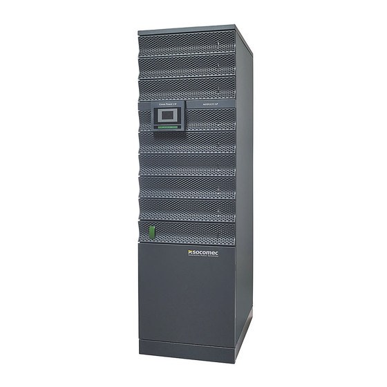
MODULYS Green Power
Руководство по установке и эксплуатации
F r o m 2 0 t o 2 4 0 k V A
Installations- und bedienungsanleitung
Installation and operating manual
Manual de instalación y uso
Manuel d'installation et d'utilisation
Manuale di installazione e uso
Installatie– en bedieningshandleiding
Dokumentacja Techniczno-Ruchowa
Manual de instalação e funcionamento
Manual de instalare şi utilizare
Navodila za priključitev in uporabo
DE
GB
ES
FR
IT
NL
PL
PT
RO
RU
SI
Advertisement
Table of Contents

Related Manuals for socomec MODULYS Green Power


Summary of Contents for socomec MODULYS Green Power
- Page 1 MODULYS Green Power F r o m 2 0 t o 2 4 0 k V A Installations- und bedienungsanleitung Installation and operating manual Manual de instalación y uso Manuel d’installation et d’utilisation Manuale di installazione e uso Installatie– en bedieningshandleiding Dokumentacja Techniczno-Ruchowa Manual de instalação e funcionamento...
- Page 2 UPS inactivity. SOCOMEC UPS may, at its own discretion, opt for the repair of the product or for the replacement of the faulty or defective parts with new parts or with used parts that are equivalent to new parts with regard to functions and performance.
-
Page 3: Table Of Contents
12. TECHNICAL SPECIFICATION ..........32 MODULYS Green Power - Ref.: IOMMODGPXX01-GB 00... -
Page 4: Safety Standard
• Keep this manual handy for future consultation. • The unit must be installed and activated only by qualified technical personnel and authorised by SOCOMEC UPS. The UPS MUST only be moved by two people at least. The people MUST take position at the sides of the UPS with respect to the direction of movement. -
Page 5: Description Of The Symbols Used On The Labels Applied To The Unit
For such uses we would advise you to contact SOCOMEC UPS beforehand to confirm the ability of these products to meet the requested level of safety, performance, reliability and compliance with applicable laws, regulations and specifications. -
Page 6: Requisites
Do not use any air conditioning or similar facility that blows air directly onto the rear side of the UPS. 2.1-1 2.1-2 20 cm 20 cm MODULYS GP MODULYS GP MODULYS GP OR OTHER OR OTHER OR OTHER MODULYS GP MODULYS GP CABINET CABINET CABINET 5 cm 5 cm 5 cm MODULYS Green Power - Ref.: IOMMODGPXX01-GB 00... -
Page 7: Electrical Requisites
In the event of three-phase distorting loads connected in output, the current on the neutral conductor may have a value that is 1.5 - 2 times the phase value (also for the input bypass). In this case, size the neutral cables and the input/output protection adequately. MODULYS Green Power - Ref.: IOMMODGPXX01-GB 00... -
Page 8: Unpacking
The carton and the original packaging must remain sealed to prevent any possible damage from mouse or similar creatures. Connect and power the loading only when the battery is fully charged. The purpose is to make sure that the UPS can provide the backup power to loads when a blackout occurs. MODULYS Green Power - Ref.: IOMMODGPXX01-GB 00... -
Page 9: Unpacking
UPS the supporting force Use screw bolts to fix Before moving UPS, make the top wooden plate Down sure to switch off the stop onto pallet of caster first MODULYS Green Power - Ref.: IOMMODGPXX01-GB 00... -
Page 10: Installation Environment And Position
4. Attach the balance supporter to the UPS with bolts. The UPS may topple over under unexpected conditions withoug balance supporter. Be sure to mount two balance supporters on both sides of the UPS for safety reasons. 3.5.2-2 Balance Supporter MODULYS Green Power - Ref.: IOMMODGPXX01-GB 00... -
Page 11: Front And Rear Views
FRONT AND REAR VIEWS Input Output Parallel Slots for optional Mimic panel port Dry Contact communication cards Dry Contact OUTPUT AUX MAINS INPUT 225A 225A 225A BY-PASS Power Output By-pass Aux Mains Input connections MODULYS Green Power - Ref.: IOMMODGPXX01-GB 00... -
Page 12: Connections
MAINS SUPPLY AUXILIARY MAINS EXT BATTERY OUTPUT MAINS AUX MAINS LOAD 5.2. Mains and Aux Mains connected in common 5.2-1 240V DC 240V DC MAINS SUPPLY AUXILIARY MAINS EXT BATTERY OUTPUT MAINS LOAD MODULYS Green Power - Ref.: IOMMODGPXX01-GB 00... -
Page 13: External Battery Cabinet Connection
CONFIG > BATTERY SETTING menu to correct the settings. Use lead acid batteries with 12 VDC nominal volt- age (MR 20+20) Cable length: 10 m max 5.3-1 240V DC 240V DC MAINS SUPPLY AUXILIARY MAINS EXT BATTERY OUTPUT TO BATTERY CABINET MODULYS Green Power - Ref.: IOMMODGPXX01-GB 00... -
Page 14: Parallel Connection
Output Aux mains UPS1 MAINS 1 Mains Parallel Port AUX MAINS 2 Output 1 Aux mains Output UPS2 MAINS 2 Mains Parallel Port EXTERNAL COUPLING CABINET Output breaker AUX COMM LOAD Bypass breaker MODULYS Green Power - Ref.: IOMMODGPXX01-GB 00... - Page 15 Wiring (Parallel Redundancy, Dual Input MAINS MAINS Output 1 Output Aux mains UPS1 Mains Parallel Port Output 1 Aux mains Output UPS2 Mains Parallel Port EXTERNAL COUPLING CABINET Output breaker AUX COMM LOAD Bypass breaker MODULYS Green Power - Ref.: IOMMODGPXX01-GB 00...
-
Page 16: Power Module Installation
Before removing any Power Module, ensure that the remaining Power Modules can support the load. CAUTION! Power module are heavy. Two people are required for handling. 6.1. Installation 6.1-1 6.1-2 6.1-3 6.1-4 6.1-5 6.1-6 6.1-7 6.1-8 6.1-9 6.1-10 6.1-11 MODULYS Green Power - Ref.: IOMMODGPXX01-GB 00... -
Page 17: Status Led Indicators For Power Module
While releasing the locking latch of power module during normal mode, the power module is off line and discharges the DC bus until the DC bus voltage reaches safety level. Then, the LED will be off. 6.2-1 Status LED Locking device MODULYS Green Power - Ref.: IOMMODGPXX01-GB 00... -
Page 18: Mimic Panel
· ESC: exit from the current menu/parameter/action; · UP : scrolls the available menus/values upwards. · DOWN : scrolls the available menus/values downwards. · ENTER: enters the menu displayed on the screen to confirm the choice/changes made. 7.1-2 Ideograms MODULYS Green Power - Ref.: IOMMODGPXX01-GB 00... -
Page 19: Meaning Of Ideograms
Output power supply present but unsta- ble or temporary Load on by-pass. YELLOW Load on battery Mode Redundacy lost GREEN flashing Battery test in progress Output power supply available and regular by inverter. GREEN Load on inverter MODULYS Green Power - Ref.: IOMMODGPXX01-GB 00... -
Page 20: Lcd Display Hierachy
CHARGER SETTING PARALLEL SETTING CONTROL AND TEST LOCAL SETTING SERVICE COMMISSIONING CLEAR STATISTICS SERIAL NUMBER CLEAR LOG FW VERSION MAINTENANCE ALARM STATISTICS COMMISSIONING LOGGING POWER FACTOR ADVANCE FW UPGRADE Admin password required. OTHERS MODULYS Green Power - Ref.: IOMMODGPXX01-GB 00... -
Page 21: Operating Procedures
This operating mode is useful when maintenance needs to be carried out on the UPS since service personnel can work on the installation without having to cut off the power supply to the load. MODULYS Green Power - Ref.: IOMMODGPXX01-GB 00... -
Page 22: Commissioning
5. When the inverter startup is completed, the UPS will transfer to Inverter mode and the luminous bar turns to yellow colour. 6. The load is powered by the ups in battery mode. MODULYS Green Power - Ref.: IOMMODGPXX01-GB 00... - Page 23 8. Press the “ON” button for 3 seconds until you hear a “beep” and then release the button. The LCD screen will show "SELF DIAGNOSIS". 9. The load is powered by the ups in normal mode (LOAD PROTECTED). MODULYS Green Power - Ref.: IOMMODGPXX01-GB 00...
-
Page 24: Two Units In Parallel (Up To 240 Kva)
5. Press the “ON” button for 3 seconds until you hear a “beep” and then release the button. The LCD screen will show "SELF DIAGNOSIS" and after 30 seconds the load is powered by the ups. Repeat the procedure for each UPS. MODULYS Green Power - Ref.: IOMMODGPXX01-GB 00... -
Page 25: Power Module Replacement
Before removing any Power Module, ensure that the remaining Power Modules can support the load. Follow the instructions below to replace the Power Module in the system. CAUTION! Power module are heavy. Two people are required for handling. MODULYS Green Power - Ref.: IOMMODGPXX01-GB 00... - Page 26 9. POWER MODULE REPLACEMENT 9.2-1 9.2-2 9.2-3 9.2-4 9.2-5 9.2-6 9.2-7 9.2-8 9.2-9 9.2-10 9.2-11 9.2-11 9.2-10 9.2-11 MODULYS Green Power - Ref.: IOMMODGPXX01-GB 00...
-
Page 27: Communication Interface
• P2 (3,4) - REMOTE SHUTDOWN FUNCTION: available in Normal Mode and Battery Mode. The UPS switches off after 1 minute. P3-P4-P5-P6 - External Battery Cabinet Temperature Available as standard, the “sensor kit” allows to detect the temperature of external battery cabinet. P7 - Reserved MODULYS Green Power - Ref.: IOMMODGPXX01-GB 00... -
Page 28: Output Dry Contact
For redundancy or for increasing the power, two UPSs can be installed via a parallel communication cable. Use the parallel communication cable provided in the accessory pack. Linking the UPS with other cables will result in accidents. Both dip-switches has to be set to ON. MODULYS Green Power - Ref.: IOMMODGPXX01-GB 00... -
Page 29: Snmp Card
MODBUS protocol over TCP/IP allows to connect the UPS to a network (Ethernet connection). 10.7. EMD - Environmental Monitoring Device (option) It is a digital environmental monitoring system for the surveillance of networking cabinet’s temperature, humidity and secures alarms in the room environment. MODULYS Green Power - Ref.: IOMMODGPXX01-GB 00... -
Page 30: Troubleshooting
PWR UNIT #n INV SHORT CIRCUIT SHUTDOWN (220/230/240 V) ± 1% PWR UNIT #n INV STS FAIL SHUTDOWN UPS output short circuit PWR UNIT #n DC BUS NOK SHUTDOWN Power module #n STS open/short MODULYS Green Power - Ref.: IOMMODGPXX01-GB 00... -
Page 31: Preventative Maintenance
Furthermore, during the operating life of the battery, Modulys green power stores statistics on the conditions of use of the battery for analysis. -
Page 32: Technical Specification
EN 62040-1 (NEMKO certified), EN 60950-1 Type and performance EN 62040-3 [VFI-SS-111] EN 62040-2 Product certification Degree of protection IP20 For source THDV < 2% and nominal load. From inverter. @ 25 °C, set by After Sales Sevice. MODULYS Green Power - Ref.: IOMMODGPXX01-GB 00... - Page 34 S A L E S , M A R K E T I N G A N D S E R V I C E M A N A G E M E N T SOCOMEC GROUP SOCOMEC UPS Paris S.A. SOCOMEC capital 11 303 400 E - R.C.S. Strasbourg B 548 500 149 95, rue Pierre Grange B.P. 60010 - 1, rue de Westhouse - F-67235 Benfeld Cedex F-94132 Fontenay-sous-Bois Cedex - FRANCE Tel.
Need help?
Do you have a question about the MODULYS Green Power and is the answer not in the manual?
Questions and answers