Table of Contents
Advertisement
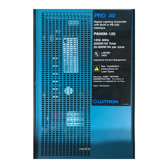
PRO AV Digital Lighting Controller (DLC)
Installation Guide
Models
PAV6M-120/PAV6S-120 PAV6M-230/PAV6S-230
PRO AV DLC Control Units
operate up to six zones of lighting.
These units can control the intensity
of all the light sources in a room.
You can adjust the lights for any
activity with the press of a button or
from an AV Control System.
(CE Models)
IMPORTANT!
Pro AV DLC lighting controls must be installed by a qualified electrician in accordance with all applicable regulations. Improper wiring can result in
personal injury or damage to Pro AV lighting controls or other equipment.
Always turn off circuit breaker/MCB or remove main fuse from power line before doing any work.
To avoid overheating and possible damage to equipment, do not install dimming devices to dim receptacles, motor-operated appliances, or dimmable
fluorescent lighting not equipped with Lutron Hi-Lume
When used with Low Voltage lighting, do not remove factory-installed bypass jumpers on load circuit terminals until load circuits are tested (see start-up
procedure on page 6.)
The Pro AV DLC dimming modules are designed to operate in ambient temperatures between 0 °C-40 °C (32 °F-104 °F).
To reduce the risk of overheating and possible damage to other equipment, the module must be mounted as shown. Failure to provide adequate space for
cooling may result in overheating and void the warranty.
Module hums slightly during operation and the internal relay clicks when the circuit is turned on and off. Choose an installation location where these
sounds are acceptable.
When used with low-voltage lighting, do not operate Pro AV DLC lighting controls with any lamps removed or burned out; Replace any burned out lamps
immediately. Use only low-voltage transformers that incorporate thermal protection or fused primary windings.
Pro AV DLC lighting controls are designed for commercial indoor use only.
T
his control uses Class 2/PELV wiring methods. Check with your local electrical inspector for compliance with national and local codes and wiring
practices.
PLEASE LEAVE FOR OCCUPANT
, Eco-10
, or Tu-Wire
Electronic Dimming Ballasts.
®
™
™
AV Control Systems
(US Models)
Advertisement
Table of Contents

Related Manuals for Lutron Electronics PAV6M-120


Summary of Contents for Lutron Electronics PAV6M-120
-
Page 1: Installation Guide
PRO AV Digital Lighting Controller (DLC) Installation Guide Models PAV6M-120/PAV6S-120 PAV6M-230/PAV6S-230 PLEASE LEAVE FOR OCCUPANT PRO AV DLC Control Units operate up to six zones of lighting. These units can control the intensity of all the light sources in a room. -
Page 2: Table Of Contents
Do you have: Then read this ..on page: Control Unit only? STEP 1: Installing PRO AV DLC Series Control Units..............3 Follow Step 1 and Step 3 How to Wire and mount PRO AV DLC Series Control Units. Wallstations? STEP 2: Wiring Instructions ......................4 Control Unit Mounting and Wiring... -
Page 3: Step 1: Installing Pro Av Dlc Series Control Units
Step 1: Installing PRO AV DLC Series Control Units This section shows how to install the PRO AV DLC. Mounting and Dimensions 1. Choose an appropriate location. Airspace Required Select a convenient location, such as an electrical closet AV Front View room or above a ceiling (non-plenum). -
Page 4: Step 2: Wiring Instructions
Step 2: Wiring Instructions Line Voltage/Mains Wiring. First, turn power off. WARNING: Turn power OFF to all circuits before installing any part of the Dimming System. Wiring with the power on can result in serious personal injury or damage to equipment. 1. -
Page 5: Step 3: Installing Wallstation Controls
Small project: A Control Unit with up to two Wallstations Controls Each Control Unit can power up to two Wallstation Controls. If you need to power more than two Wallstation Controls from one Control Unit, install an external 12VDC power supply as described on page 13. DATA LINK: 4: MUX 3: MUX... -
Page 6: Step 4: Start-Up Procedure
Set DIP switches 5, 6 and/or 7 to specify function For most Wallstations, you must also set DIP switches to specify exactly how the Wallstation is to function. Please refer to the Instructions shipped with each Wallstation for more detailed information. NTGRX-4S, -4S-DW, -4S-IR, -CIR, -4B Scene Selection Control NTGRX-2B-SL Multi-Control Switches 5 and 6 determine which scenes the unit will select:... -
Page 7: Step 5: Rs232 Wiring
Step 5: RS232 Wiring 50 ft. (15 m) maximum To PC or AV Equipment RS232 Link STEP 6: Setting Up PRO AV DLC Control Units TO ENTER (EXIT) SETUP MODE: This section shows how to set up a PRO AV DLC Control Unit, PRESS AND HOLD FOR ABOUT 3 SECONDS UNTIL including: LEDs CYCLE (STOP CYCLING) -
Page 8: Step 7: Setting Up Rs232 Communication
Identifying the load type for each zone Lutron ships PRO AV DLC Control Units with all zones set for incandescent/halogen (tungsten) lighting. If your project has non-incandescent loads, change all non-incandescent zones to the correct load type, through GRX Liaison or AV Control System. Set up a Wallstation Control to “talk”... - Page 9 Unit Addressed as: Indicated by: Control Unit A or a B or b C or c D or d E or e F or f G or g H or h Unit Addressed as: Indicated by: Wallstation I or i J or j K or k L or l...
-
Page 10: Appendix A: More About Class 2/Pelv Wiring
Appendix A: More about Class 2/PELV Wiring EACH TERMINAL CAN ACCEPT UP TO 2 #18 This appendix explains the Class 2/PELV wiring used to carry communications between PRO AV DLC Control AWG (1.0 mm ) WIRES Units and Wallstation Controls. Lutron requires that you connect (daisy-chain) all PRO AV DLC Control Units, Wallstations, and Accessories with two twisted pair for operation. -
Page 11: Appendix C: Power Boosters And Load Interfaces
Appendix C: Power Boosters and Load Interfaces This “load-side” equipment installs on the zone wiring between CAUTION! Test load for short circuits. the Control Unit and the lighting load. The NGRX-PB increases a Control Unit’s zone load capacity Turn power off. HOT/LIVE SWITCH for Incandescent/Halogen (Tungsten), Magnetic Low Voltage,... -
Page 12: Appendix D: Grx-Tvi 0-10 Volt Ballast Interface
Appendix D: GRX-TVI 0-10 Volt Ballast/Switching Interface Specifications FEATURES Provides a Class 2/PELV isolated 0-10V output signal. The GRX-TVI provides 0-10V control and ballast switching capabilities in one en- Complies with UL Standard 508. Accepts a zone output signal from PRO AV DLC closure. -
Page 13: Appendix E: Hp Dimming Modules
Appendix E: HP Dimming Modules (120V control feed only) Not for use with generator-supplied power! Specifications HP 2•4•6 Modules increase the load capacity of a DESCRIPTION MODEL CAPACITY@ No. OF OUTPUTS Control Unit zone from 800W/VA to: NUMBER TO LOAD CIRCUITS 120VAC, 20A HP•2 1920W/VA... -
Page 14: Appendix F: Infrared Transmitters/Receivers
Appendix F: Infrared Transmitters/Receivers GRX-IT GRX-8IT Transmitters/Receivers SCENE SCENE PRO AV DLC Control Units can be used with the ceiling IR Receiver (GRX-CIR) or SCENE BUTTONS BUTTONS BUTTONS a Wallstation IR Control (NTGRX-4SIR-WH). This allows control of the Control (1—4) (1—4) (5—8) Unit with the optional Handheld Infrared Wireless Remote Control Transmitters. - Page 15 Page 15...
- Page 16 370,663; DES 378,814 and corresponding foreign patents. U.S. and foreign patents pending. Lutron, PRO AV DLC, and Hi-lume are registered trademarks; Hi-Power, Eco-10, LIAISON, Designer, Tu-Wire, and Architrave are trademarks of Lutron Electronics Co., Inc. © 1999 Lutron Electronics Co., Inc.
Need help?
Do you have a question about the PAV6M-120 and is the answer not in the manual?
Questions and answers