Advertisement
Quick Links
LUTRON
®
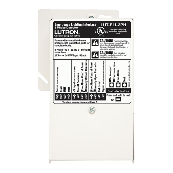
LUT-ELI-3PH
Emergency Lighting Interface
Description
• The LUT-ELI-3PH unit is to be used in conjunction with
Lutron GP, LP, LCP, XP, and XPS panels, RadioTouch
controllers, EcoSystem
Node
units, GRAFIK Eye
TM
lighting management hubs.
• The LUT-ELI-3PH unit is UL924 Listed as "Emergency
Lighting and Power Equipment."
• The LUT-ELI-3PH senses the normal (non-essential) line
voltage on all three phases of normal power. When one
or more phases of power are lost, the LUT-ELI-3PH unit
will send a signal to the RadioTouch controller, panel
circuit selector/controller, EcoSystem bus supply, Energi
Savr Node unit, GRAFIK Eye QS system or Quantum bus
supply with emergency (essential) power, causing it to
enter the emergency lighting mode. Any lights controlled
by these devices will go to the emergency light level
setting.
• When used with a Energi Savr Node unit, EcoSystem or
Quantum bus supply, a separate 24 V
supply must be used to power the LUT-ELI-3PH unit.
Features
• Can be added to an existing system.
• Status indicator, indicates the phase status. Indicator ON
is normal mode, OFF is emergency mode.
• A test button is provided to perform a functional test of
the system by simulating an emergency situation.
• The interface has inputs for a Fire Alarm Control Panel
(FACP). A maintained dry contact closure received
between the FACP inputs will actuate the emergency
mode.
S P E C I F I C AT I O N S U b M I T TA L
Job Name:
Job Number:
bus supplies, Energi Savr
®
QS units, and Quantum
®
Rasterized
50 mA power
Model Numbers:
LUT-ELI-3PH
®
®
GND
Power Accessories
12
12
11
11
10
10
9
9
8
8
7
7
6
6
5
5
4
4
3
3
2
2
CLASS 2 LOW VOLTAGE WIRING
P/N 369-299B
1 11.11.10
1
1
S1
Page
1
Advertisement

Related Manuals for Lutron Electronics LUT-ELI-3PH


Summary of Contents for Lutron Electronics LUT-ELI-3PH
- Page 1 LUTRON Power Accessories LUT-ELI-3PH ® P/N 369-299B 1 11.11.10 LUT-ELI-3PH Emergency Lighting Interface Description • The LUT-ELI-3PH unit is to be used in conjunction with Lutron GP, LP, LCP, XP, and XPS panels, RadioTouch ® controllers, EcoSystem bus supplies, Energi Savr ® Node units, GRAFIK Eye QS units, and Quantum ® ® lighting management hubs. • The LUT-ELI-3PH unit is UL924 Listed as “Emergency Lighting and Power Equipment.” • The LUT-ELI-3PH senses the normal (non-essential) line voltage on all three phases of normal power. When one or more phases of power are lost, the LUT-ELI-3PH unit will send a signal to the RadioTouch controller, panel circuit selector/controller, EcoSystem bus supply, Energi Savr Node unit, GRAFIK Eye QS system or Quantum bus supply with emergency (essential) power, causing it to enter the emergency lighting mode. Any lights controlled...
-
Page 2: Specifications
LUTRON Power Accessories LUT-ELI-3PH ® P/N 369-299B 2 11.11.10 Specifications Power System Communications and Capacity • Sense voltage input to the LUT-ELI-3PH unit must be • May be added to an existing Lutron system. from the Normal (Non-Essential) power source. • One LUT-ELI-3PH unit may be used with up to • Sense voltage range: 100-347 V 50/60 Hz 30 mA, 32 circuit selectors or controllers, 100 RadioTouch ® 1 Phase or 3 Phase. controllers, or 32 EcoSystem bus supplies, ® 32 Energi Savr Node units, 32 GRAFIK Eye QS units or ® • Proper short-circuit and over-current protection must 32 Quantum bus supplies. ®... -
Page 3: Dimensions And Mounting
LUTRON Power Accessories LUT-ELI-3PH ® P/N 369-299B 3 11.11.10 Dimensions and Mounting Front View Side View 5.00 in 2.50 in (127 mm) (63.5 mm) 7.75 in (196.85 mm) CLASS 2 LOW VOLTAGE WIRING Mounting Example Side View (Cross-Section) 4 x 4 in (102 x 102 mm) For line voltage Junction box wiring only LUT-ELI-3PH WALL UNIT Insert Class 2/PELV ®... - Page 4 LUTRON Power Accessories LUT-ELI-3PH ® P/N 369-299B 4 11.11.10 Line Voltage Wiring Examples: 3-Phase Diagram Ground Neutral Phase C Normal Power Phase B Phase A Normal Power Guide to Power Source Wiring Wire: Connects to: Phase A Phase B Phase C...
- Page 5 IRCUIT ELECT IRCUIT CLASS 2 LOW VOLTAGE WIRING Circuit Circuit Panel 1 Panel 2 • One LUT-ELI-3PH unit may be connected in parallel with up to 32 circuit selectors. • LUT-ELI-3PH unit may be placed anywhere on the power panel link. Rasterized • Switch position SW6 on the circuit selector/controller must be in the right-most position, ‘(Essential)’ on all Emergency Panels. • The LUT-ELI-3PH unit 24 V input must always be connected to at least one of the Emergency Panels. S P E C I F I C AT I O N S U b M I T TA L...
- Page 6 3 ,4 1 2 3 4 D 5 1 2 3 4 1 2 3 4 D 5 1 2 3 4 CLASS 2 LOW VOLTAGE WIRING Panel 1 Panel 2 • One LUT-ELI-3PH unit may be connected in parallel with up to 32 LCP/XPS controllers. • LUT-ELI-3PH unit may be placed anywhere on the power panel link. Rasterized • Switch position SW6 on the controller must be in the right-most position, ‘(Essential)’ on all Emergency Panels. • The LUT-ELI-3PH unit 24 V input must always be connected to at least one of the Emergency Panels. S P E C I F I C AT I O N S U b M I T TA L...
- Page 7 (2) Signal To additional Rasterized RadioTouch (6) Circuit Common controllers (100 maximum) (4) 24 V • One LUT-ELI-3PH unit may be connected in parallel with up to 100 RadioTouch controllers. • DIP switch #2 on the RadioTouch controller must be in the down position. • When wiring a RadioTouch controller for emergency lighting it cannot be controlled by an occupancy sensor. S P E C I F I C AT I O N S U b M I T TA L Page Job Name:...
- Page 8 24 V Emerg. (terminal 6) 100-277 V Normal/ Emergency Connect up to 32 supply bus supplies Wiring Summary: • Wire power pack red wire (+24 V) to LUT-ELI-3PH unit terminal 8 (+24VFW). • Wire power pack black wire (Common) to LUT-ELI-3PH unit terminal 7 (Common) and to EcoSystem bus supply terminal 5 (Common). • Wire Signal wire from LUT-ELI-3PH unit (terminal 1) to EcoSystem bus supply terminal 6 (CCI-Emergency). Note: When normal power fails and the LUT-ELI-3PH unit trips, the EcoSystem bus supply stops powering the EcoSystem bus, and all ballasts will turn on to their emergency light level. Note: The LUT-ELI-3PH unit includes 2 Fire Alarm Control Panel (FACP) inputs as well. Consult the LUT-ELI-3PH unit instructions for wiring details. S P E C I F I C AT I O N S U b M I T TA L...
- Page 9 Neutral Common Emergency supply 100-347 V Normal supply Com – Common CLASS 2 LOW VOLTAGE WIRING Emerg – Emergency Wiring Summary: • Wire power pack red wire (+24 V) to LUT-ELI-3PH unit terminal 8 (V+). • Wire power pack black wire (Common) to LUT-ELI-3PH unit terminal 7 (Circuit Common) and to Energi Savr Node ‘Com’ terminal of Emergency Contact Closure Input. • Wire Signal wire from LUT-ELI-3PH unit (terminal 1) to Energi Savr Node ‘Emerg’ terminal of Emergency Contact Closure Input. • Removing power from LUT-ELI-3PH unit sends all programmed zones to emergency light levels (Default is typically 100%). • Reapplying power to LUT-ELI-3PH unit causes all programmed zones to return to previous light levels. Note: When normal power fails and the LUT-ELI-3PH unit trips, the signal output changes state and all loads will turn on to their emergency light level. Note: The LUT-ELI-3PH unit includes 2 Fire Alarm Control Panel (FACP) inputs as well. Consult the LUT-ELI-3PH unit instructions for wiring details. S P E C I F I C AT I O N S U b M I T TA L...
- Page 10 Neutral 100-347 V Normal supply Common EM C CLASS 2 LOW VOLTAGE WIRING Emerg. signal Wiring Summary: • Wire power pack red wire (+24 V) to LUT-ELI-3PH unit terminal 8 (+VFW). • Wire power pack black wire (Common) to LUT-ELI-3PH unit terminal 7 (Common) and to Quantum bus supply terminal 5 (Common). • Wire Signal wire from LUT-ELI-3PH unit (terminal 1) to Quantum bus supply terminal 6 (CCI-Emergency). Note: When normal power fails and the LUT-ELI-3PH unit trips, the Quantum bus supply stops powering the Quantum bus, and all ballasts will turn on to their emergency light level. Note: The LUT-ELI-3PH unit includes 2 Fire Alarm Control Panel (FACP) inputs as well. Consult the LUT-ELI-3PH unit instructions for wiring details. S P E C I F I C AT I O N S U b M I T TA L...
- Page 11 LUTRON Power Accessories LUT-ELI-3PH ® P/N 369-299B 11 11.11.10 Installing a LUT-ELI-3PH Unit with a GRAFIK Eye QS Unit ® Wiring to a GRAFIK Eye QS Control Unit Note: F or 1-phase 2-wire application, connect phase A, b, and C wires on LUT-ELI-3PH together for phase sensing. 100-347 V Normal supply GRAFIK Eye QS unit (back view) (3) 18 AWG TAGE WIRING TAGE WIRING (0.75 mm²)
- Page 12 LUTRON Power Accessories LUT-ELI-3PH ® P/N 369-299B 12 11.11.10 Class 2/PELV Wiring Example: ® Fire Alarm Control Panel (FACP) Important Normally Open FACP Input Use only with normally open (terminals 3 and 4) or normally closed (terminals 5 and 6) dry contact closure. When the proper contact LUT-ELI-3PH Unit state is triggered, it must be maintained for the LUT-ELI-3PH unit to go into Emergency Mode. Once the contact is released, the LUT-ELI-3PH unit will return the GRAFIK Systems GP, LP, ® XP panel(s), XPS, LCP, RadioTouch controller, ® EcoSystem bus Supply, GRAFIK Eye QS ®...
Need help?
Do you have a question about the LUT-ELI-3PH and is the answer not in the manual?
Questions and answers