Advertisement
Available languages
Available languages
Quick Links
Installation Instructions
Please Read Before Installing
P/N 041882 Rev. A
Important Notes:
• For installation by a qualified electrician in accordance with all local and national
electrical codes.
• Use copper conductors only.
• For indoor use only.
• For 277 V~ applications, a suitable barrier may be required between the non-Class 2
and Class 2 wiring, per local and national electrical wiring codes. For your
convenience, the power interface includes an optional barrier.
• DO NOT install if product has any visible damage.
• If moisture or condensation is evident, allow the product to dry completely
before installation.
• Operate between 32 °F (0 °C) and 104 °F (40 °C) ambient.
• 0% to 90% humidity, non-condensing.
• Four 8-32 × 3/8 in (9.5 mm), serrated lid screws provided.
Required Components
For each system, ensure that you have:
Lumaris Wireless Controller
(3 controllers max per power interface)
RRL-TWCL-WH - RadioRA 3
HWL-TWCL-WH - HomeWorks QSX
Barrel-to-Terminal Adapter
(3 included)
Power Interface
(LU-PH3-A)
(LU-BP1)
Troubleshooting
Indicator LED Flash Pattern
Reason
LED on wireless controller is off
No power to the wireless controller
Red LED on wireless controller flashes once,
Output short circuited
then a 2 second pause.
Red LED on wireless controller flashes three
Input voltage is too low
times, then a 2 second pause.
Red LED on wireless controller flashes four
Input voltage is too high
times, then a 2 second pause.
Green LED on wireless controller is on
Device is not commissioned
continuously.
Customer Assistance:
U.S.A. / Canada: 1.844.LUTRON1
Mexico: +1.888.235.2910
www.lutron.com
Limited Warranty:
For limited warranty information, please visit http://www.lutron.com/TechnicalDocumentLibrary/043492.pdf
Lutron Elec tron ics Co., Inc. | 7200 Suter Road | Coopersburg, PA 18036-1299
English
1
Mount the power interface
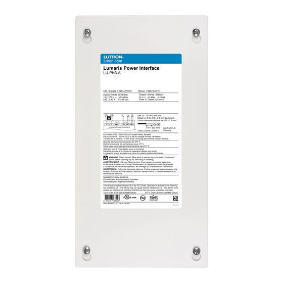
Lumaris Power Interface
LU-PH3-A
1. Remove the top cover to access the multi-sided mounting key holes.
Input: 120 V~/277 V~ 50 / 60 Hz
2. Mount the power interface per the options shown below.
Output: 96 W 24 V-
Notes
• A minimum of 3 in (76 mm) is required between any two power interfaces.
• Mount the power interface in a position where it can be easily located and accessed if service
or troubleshooting is necessary.
• Any other mounting configurations will require additional mechanical support. Improper
installation may result in hazards to personnel or property.
Option 1
Output
Input
Option 3
Mounting Surface
A barrier (included) in the wiring compartment separates non-Class 2 and Class 2 wires.
Barrier can be placed between the control and the output terminals (Option 1) or between the
input and the control terminals (Option 2).
2
Wiring
!
WARNING: Shock Hazard. May result in serious injury or death.
Turn off power at circuit breaker before installing the unit.
1. Remove the top cover to access the terminal blocks.
2. Open the necessary knockouts to pass wires into the wiring compartment.
3. Determine the length and wire gauge from the power interface to the wireless controller
using Table 1.
4. If wiring wireless controllers in a multi-zone application, wire as shown in Wiring Diagram A.
Remedy
Confirm that the circuit breaker is on to the
If wiring wireless controllers in a single zone application, wire as shown in Wiring Diagram B.
power interface and that the line voltage wiring
is connected to the proper terminals.
5. Connect the necessary wires as shown in the wiring diagram and plug in the barrel-to-
Disconnect the load from the wireless controller
terminal adapter to the wireless controller. Terminals accept 12 AWG to 20 AWG
and check for shorts. Power cycle the wireless
controller to reset.
(4.0 mm
2
to 0.50 mm
Confirm that the wireless controller is being
16 AWG to 20 AWG (1.0 mm
powered by 24 V- +/- 10%. Confirm proper
Note: If using 14 AWG (2.5 mm
wire gauge and length are used from Table 1.
power interface to the barrel-to-terminal adapter, splice a small piece of 16 AWG (1.0 mm
Setup the device in a system.
onto a 12 AWG (4.0 mm
6. Optional - Add barrier between non-Class 2 and Class 2 wires.
7. Re-apply power.
Note: Table 1 wiring information is based on a Lumaris power interface controlling three
Lumaris wireless controllers, each with 16.4 ft (5 m) of LED tape. Contact Lutron if longer
wire runs are required.
The Lutron logo, Lutron, RadioRA 3, HomeWorks, and Lumaris are trademarks or registered trademarks of Lutron Electronics Co., Inc. in the US and/or
other countries. All other product names, logos, and brands are property of their respective owners. ©2023 Lutron Electronics Co., Inc.
Option 2
Barrier
Barrier
Output
2
) on the power interface. Barrel-to-terminal adapter terminals accept
2
2
to 0.50 mm
). Torque to 5 in-lbs (0.5 N•m).
2
) or 12 AWG (4.0 mm
2
) wire for LED+ and LED- wires from the
2
2
) or 14 AWG (2.5 mm
) wire to insert into the barrel-to-terminal adapter.
2
Wiring (continued)
Table 1: Maximum Wire Length from the Power Supply to the Wireless Controller: ft (m)
12 AWG
14 AWG
(4.0 mm
2
)
(2.5 mm
2
)
75 (22.9)
50 (15.2)
Wiring Diagram A: Multi-zone application
Note: To avoid unintended interaction between LEDs, all wireless controllers that are controlled
separately in a multi-zone application must be homerun back to the power interface.
Zone 1
Zone 2
}
Line / Hot
Neutral
120 / 277 V~
Ground
Input
LED
LED
N/C
L
N
D
(-)
(+)
Wire length calculation
example: If using 16 AWG
(1.0 mm
2
) wire, total length
of each wire (LED + or LED-)
must be 30 ft (9.1 m) or less.
Maximum wire length from
each wireless controller to
LED tape is 10 ft (3 m)
LU-PH3-A Power Interface
Wiring Diagram B: Single zone application
Note: If wiring wireless controllers in a single zone application, LED+ and LED- low-voltage wires can
be T-tapped or can be homerun back to the power interface. Either wiring method is acceptable.
}
Line / Hot
Neutral
120 / 277 V~
Ground
LED
LED
D
N/C
L
N
(-)
(+)
Wire length calculation
example: If using 16 AWG
2
) wire
(1.0 mm
2
) wire, the total
length of each wire (LED+
or LED-) must be 30 ft
(9.1 m) or less.
Maximum wire length from
each wireless controller to
LED tape is 10 ft (3 m).
LU-PH3-A Power Interface
16 AWG
18 AWG
20 AWG
(1.0 mm
2
)
(0.75 mm
2
)
(0.50 mm
2
)
30 (9.1)
20 (6.1)
10 (3.0)
LED+
LED-
Wireless Controller
R
R
R
R
W
W
W
W
B
B
B
B
A
B
C
D
R
R
R
R
W
W
W
W
B
B
B
B
A
B
C
D
Zone 1
Wireless Controller
R
R
R
R
W
W
W
W
B
B
B
B
A
B
C
D
R
R
R
R
W
W
W
W
B
B
B
B
A
B
C
D
R
R
R
R
W
W
W
W
B
B
B
B
A
B
C
D
Advertisement

Subscribe to Our Youtube Channel
Related Manuals for Lutron Electronics LU-PH3-A


Summary of Contents for Lutron Electronics LU-PH3-A
- Page 1 For limited warranty information, please visit http://www.lutron.com/TechnicalDocumentLibrary/043492.pdf The Lutron logo, Lutron, RadioRA 3, HomeWorks, and Lumaris are trademarks or registered trademarks of Lutron Electronics Co., Inc. in the US and/or Lutron Elec tron ics Co., Inc. | 7200 Suter Road | Coopersburg, PA 18036-1299...
- Page 2 DEL. Contactez Lutron si des câbles plus longs sont nécessaires. http://www.lutron.com/TechnicalDocumentLibrary/043492.pdf Le logo Lutron, Lutron, RadioRA 3, HomeWorks et Lumaris sont des marques commerciales ou déposées de Lutron Electronics Co., Inc. aux États-Unis et/ Lutron Electronics Co., Inc. | 7200 Suter Road | Coopersburg, PA 18036-1299...
- Page 3 3 m (10 pies). El logotipo de Lutron, Lutron, RadioRA 3, HomeWorks y Lumaris son marcas comerciales o marcas comerciales registradas de Lutron Electronics Co., Inc. en E.U.A. y/o en Lutron Electronics Co., Inc. | 7200 Suter Road | Coopersburg, PA 18036-1299...
Need help?
Do you have a question about the LU-PH3-A and is the answer not in the manual?
Questions and answers