Table of Contents
Advertisement
Available languages
Available languages
Quick Links
EcoSystem to 0 – 10 V- Interface | Install Guide
ATTENTION: Please read this guide before installing.
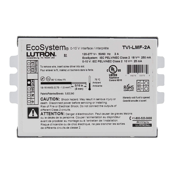
TVI-LMF-2A
120
277 V~ 50/60 Hz 2 A
–
EcoSystem: 18 V- 250 mA
0 – 10: 10 V- 25 mA
Overview
The EcoSystem to 0 –10 V- Interface provides a control
gateway from an EcoSystem link to a 0 –10 V- compatible
lighting device, typically an LED driver.
It allows for individual addressability of the 0 –10 V- device,
but only provides one-way communication from the controls
to the 0 –10 V- device. This interface is for single-fixture
control only. For fixtures that have multiple drivers installed
(such as two or three drivers being needed to reach certain
output wattages), only one interface may be necessary. This
interface is not intended for control of multiple fixtures.
System Example
EcoSystem Link
EcoSystem
Ballast
IR Receiver
EcoSystem Master*
(GRAFIK Eye QS,
Quantum hub, etc.)
Lighting Remote
*Does not count as one of the 64 devices allowed on the EcoSystem link
Customer Assistance: +1.844.LUTRON1
Specifications
Power
• Maximum interface power consumption (at any voltage):
< = 1.0 W when output load is turned on
< = 0.5 W when output load turned off ("standby")
• Relay Output:
2 A of electronic load, 5 drivers maximum
• Input power must be unswitched
0–10 V- Control
• Current rating: 25 mA max (sink only)
• Maximum 0 –10 V- wire length: 10 ft (3 m) from
interface to driver
• Class 1 or Class 2 wiring allowed, isolated from line and
EcoSystem link
• Voltage Range:
Off: < = 0.5 V-
Minimum light level:
Maximum light level: 10 V-
• Compliant to IEC 60929 Annex E2 standard
("Control by DC voltage")
Note:
It is possible to connect more than 1 driver within a fixture
to an interface, with a maximum of 5 drivers. The interface
controls up to 2 A of connected load. If more than one
driver is attached, the drivers are controlled as a single
zone—individual control of multiple attached drivers is not
possible.
TVI-LMF-2A
EcoSystem
0 –10 V- Driver
to 0 –10 V-
Interface
1 V-
EcoSystem Ballast
Keypad
English
EcoSystem
LED Driver
Lutron | 1
Advertisement
Table of Contents

Subscribe to Our Youtube Channel
Related Manuals for Lutron Electronics EcoSystem


Summary of Contents for Lutron Electronics EcoSystem
- Page 1 0 –10 V- LED Driver Ballast Interface IR Receiver EcoSystem Master* (GRAFIK Eye QS, Quantum hub, etc.) Keypad Lighting Remote *Does not count as one of the 64 devices allowed on the EcoSystem link Customer Assistance: +1.844.LUTRON1 Lutron | 1...
- Page 2 EcoSystem to 0 – 10 V- Interface | Install Guide Step 1: Mount Interface Step 2: Wire Interface to Driver(s) 0 –10 V- interfaces must be mounted to or within a WARNING - Electric Shock Hazard. May grounded, metal ULR/NECR recognized electrical enclosure, Result in Serious Injury or Death.
-
Page 3: Wiring Diagram
Wire per Class 2 wiring regulations. If EcoSystem link the interface. is wired per Class 1, the EcoSystem wires need to be 5. Make sure the driver(s) are correctly wired to the interface separated from the 0 – 10 V- wires by a barrier or 0.25 in (step 2). - Page 4 Lutron for use with the interface. Lutron Electronics Co., Inc., reserves the right to make improvements or changes in its products without prior notice. Although every attempt is made to ensure that this information is accurate and up-to-date, please check with Lutron to confirm product availability, latest specifications, and suitability for your application.
-
Page 5: Caractéristiques
Pilote EcoSystem EcoSystem vers 0 – 10 V- Récepteur EcoSystem Master* (GRAFIK Eye QS, hub Quantum, etc.) Clavier Télécommande d’éclairage * Ne compte pas comme l’un des 64 appareils autorisés sur la liaison EcoSystem Assistance technique : +1.844.LUTRON1 Lutron | 1... - Page 6 Interface EcoSystem vers 0 – 10 V- | Guide d’installation Étape 2 : Câbler l’interface au(x) pilote(s) Étape 1 : Monter l’interface AVERTISSEMENT - Risque d’électrocution. Les interfaces de 0 – 10 V- doivent être montées sur ou Peut causer des blessures graves ou la dans un boîtier électrique métallique certifié...
-
Page 7: Schéma De Câblage
Câblez en respectant les règles de câblage classe 2. Si sur l’interface. la liaison EcoSystem est câblée en classe 1, les fils de 5. Assurez-vous que les pilotes sont câblées correctement à l’EcoSystem doivent être séparés des fils de 0 – 10 V- l’interface (étape 2). - Page 8 En outre, Lutron ne sera responsable d'aucun dommage à l'interface résultant de l'utilisation de l'équipement auxiliaire non fourni par Lutron utilisé avec l'interface. Lutron Electronics Co., Inc., se réserve le droit d'apporter des améliorations ou des changements à ses produits sans préavis. Bien que tout ait été fait pour veiller à que ces informations soient exactes et à...
-
Page 9: Especificaciones
EcoSystem EcoSystem de 0 –10 V- Receptor EcoSystem Master* (GRAFIK Eye QS, Hub Quantum, etc.) Teclado Control remoto de iluminación *No cuenta como uno de los 64 dispositivos en el enlace de EcoSystem Asistencia a clientes: +1.888.235.2910 Lutron | 1... - Page 10 Interfaz de control EcoSystem de 0 –10 V- | Guía de instalación Paso 1: Instale la interfaz Paso 2: Cablee la interfaz a los controladores ADVERTENCIA - Peligro de descarga – La interfaz de 0 10 V- deben instalarse sobre un gabinete eléctrica.
-
Page 11: Diagrama De Cableado
Interfaz de control EcoSystem de 0 –10 V- | Guía de instalación Paso 2b: Cableado de 0 a 10 V- Paso 3: Cablee la red eléctrica a la interfaz (cont.) ADVERTENCIA - Riesgo de incendio o de descarga 2. Cablee la entrada línea/vivo al terminal HOT (L) eléctrica. - Page 12 Lutron para usar con la interfaz. Lutron Electronics Co., Inc., se reserva el derecho a hacer mejoras o cambios a sus productos sin previo aviso. Aunque se hace todo tipo de intentos para asegurar que esta información sea exacta y que esté...
Need help?
Do you have a question about the EcoSystem and is the answer not in the manual?
Questions and answers