Table of Contents
Advertisement
Available languages
Available languages
Quick Links
GRAFIK Systems
Installation Instructions
Occupant Copy
Please refer to the enclosed CD for the product
Specification Sheets and Operation Manuals,
Ethernet Device IP program, and RS232 and Ethernet
Protocol information.
Mounting
1. Mount the Control Interface directly on a wall, as
shown in the Mounting Diagram, using screws
(not included). When mounting, provide sufficient
space for connecting cables.
The unit can also be placed in the LUT-19AV-1U AV
rack using the screws provided with the unit. The
LUT-19AV-1U will hold up to four units.
If conduit is desired for wiring, the LUT-5x10-ENC can
be used to mount one unit.
2. Strip 4 in (10 mm) of insulation from wires. Each Data
Link terminal will accept up to two 18 AWG
(1.0 mm
2
) wires.
3. Connect wiring as shown in the Wiring Diagram
(next page). LED 1 lights continuously (Power)
and LED 7 blinks rapidly (Data Link RX) when the
2.50
SELV / PELV / NEC
Class 2 Data Link is installed
®
correctly.
Dimensions
3.75
5.26
1.06
3.75 in
(95 mm)
1.0 in
(27 mm)
Control Interface
SELV / PELV / NECR Class 2
Please Read
2.5 in
(63 mm)
4.26
5.26 in
(137 mm)
CAUTION: Risk of Fire, Explosion, Leakage, and Burns. Do Not Recharge, Disassemble, Heat Above 212 °F (100 °C) or Incinerate. This
product contains a lithium button/coin cell battery. Keep batteries away from children. If a new or used lithium button/coin cell battery is
swallowed or enters the body, it can cause severe internal burns and can lead to death in as little as 2 hours. Always completely secure
the battery compartment. If the battery compartment does not close securely, stop using the product, remove the batteries, and keep the
batteries away from children. If you think batteries might have been swallowed or placed inside any partof the body, seek immediate medical
attention. The battery in this device contains Perchlorate Material — special handling may apply. For more information, visit
www.dtsc.ca.gov/hazardouswaste/perchlorate
GRX-CI-PRG, GRX-CI-NWK-E,
GRX-CI-RS232, OMX-CI-NWK-E,
OMX-CI-RS232
QSE-CI-NWK-E
Mounting Diagram
Wall
Control Interface
Mounting
Holes
4.25 in
(108 mm)
12 V- 125 mA
or
24 V- 65 mA
24-36 V- 65 mA
LUT-19AV-1U
LUT-5x10-ENC
Wire Strip Length
3/8 in
(10 mm)
Mounting Hole Detail
0.25 in
(6 mm)
0.1875 in
(5 mm) dia.
0.3125 in
(8 mm) dia.
0.1875 in
(5 mm) dia.
#6 or #8 (M3 or M4)
screw recommended
(not included)
Advertisement
Table of Contents

Subscribe to Our Youtube Channel
Related Manuals for Lutron Electronics Grafik Eye GRX-CI-PRG


Summary of Contents for Lutron Electronics Grafik Eye GRX-CI-PRG
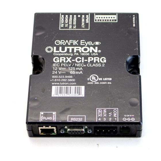
- Page 1 GRX-CI-PRG, GRX-CI-NWK-E, 12 V- 125 mA GRX-CI-RS232, OMX-CI-NWK-E, GRAFIK Systems Control Interface OMX-CI-RS232 24 V- 65 mA Installation Instructions SELV / PELV / NECR Class 2 QSE-CI-NWK-E 24-36 V- 65 mA Occupant Copy Please Read Please refer to the enclosed CD for the product Specification Sheets and Operation Manuals, Ethernet Device IP program, and RS232 and Ethernet Protocol information.
-
Page 2: Important Notes
SELV / PELV / NEC Class 2 Wiring ® Important Notes • Install in accordance with all applicable regulations. WARNING: Shock Hazard. May result in personal injury or death. Do not connect line voltage/mains power to device. • This control uses SELV / PELV / NEC Class 2 wiring methods. - Page 3 A / V Connections and Signal / Link Information GRX-CI-NWK-E, OMX-CI-NWK-E CAT5 Cable: maximum 328 ft To PC or AV Equipment. For Ethernet Link, use CAT5 cable (100 m) to connect to auxiliary equipment. The Ethernet Link LED will light continuously when link is present and will flash when there is link activity.
- Page 4 The Lutron logo, Lutron, and GRAFIK Eye are trademarks or registered trademarks of Lutron Electronics Co., Inc. in the US and/or other countries. All other product names, logos, and brands are property of their respective owners. Lutron Electronics Co., Inc. P/N 040471 Rev. A 05/2021 © 2011–2021 Lutron Electronics Co., Inc.
-
Page 5: Diagrama De Montaje
GRX-CI-PRG, GRX-CI-NWK-E, 12 V- 125 mA GRX-CI-RS232, OMX-CI-NWK-E, GRAFIK Systems Interfaz de control OMX-CI-RS232 24 V- 65 mA Instrucciones para la instalació SELV / PELV / NECR Class 2 24-36 V- 65 mA QSE-CI-NWK-E Copia del Ocupante Por Favor Léala Por favor consulte el CD adjunto por información sobre las Hojas de Especificaciones y Manuales de Operación, programa del Dispositivo IP Ethernet, y... -
Page 6: Notas Importantes
Cableado de SELV / PELV / NEC Clase 2 ® Notas Importantes • Debe instalarse de acuerdo con las regulaciones correspondientes. ADVERTENCIA: Peligro de descarga eléctrica. Puede ocasionar lesiones graves o la muerte. No conecte voltaje de línea / alimentación al dispositivo. •... - Page 7 Conexiones de A/V e Información de Señal / Enlace GRX-CI-NWK-E, OMX-CI-NWK-E Cable CAT5: A la PC o el Equipo AV. Para enlace Ethernet, use el cable máximo 100 m CAT5 para conectar el equipamiento auxiliar. El LED del (328 pi) enlace Ethernet se iluminará...
- Page 8 El logotipo de Lutron, Lutron, y GRAFIK Eye son marcas comerciales o marcas comerciales registradas de Lutron Electronics Co., Inc. en E.U.A. y/o en otros países. Todos los demás nombres de productos, logotipos y marcas son de propiedad de sus respectivos poseedores.
-
Page 9: Montage
12 V- 125 mA GRX-CI-PRG, GRX-CI-NWK-E, oder GRX-CI-RS232, OMX-CI-NWK-E, GRAFIK Systems Steuerschnittstelle 24 V- 65 mA OMX-CI-RS232 Installationsanweisungen SELV / PELV / NEC Class 2 QSE-CI-NWK-E 24-36 V- 65 mA Bewohner-Exemplar Bitte lesen Produkt-Spezifikationen und Bedienungsanleitungen, ein IP-Programm für Ethernetgeräte und Informationen zum RS232- und Ethernet-Protokoll finden Sie auf der beiliegenden CD. -
Page 10: Wichtige Hinweise
SELV / PELV / NEC Klasse 2 Verkabelung ® Wichtige Hinweise • Bei der Installation sind alle anwendbaren Regeln und Vorschriften einzuhalten. ACHTUNG! Stromschlaggefahr. Kann zu schwerer Körperverletzung oder Tod führen. Schließen Sie keine Netzspannung an das Gerät an. • Diese Steuerung ist mit Verkabelungsmethoden SELV / PELV / NEC Klasse 2 angeschlossen werden. - Page 11 A/V-Anschlüsse und Signal/Link-Informationen GRX-CI-NWK-E, OMX-CI-NWK-E CAT5-Kabel: max. 100 m An PC oder AV-Einrichtung. Für Ethernet-Link benutzen Sie das CAT5-Kabel zum Anschluss an ein Zusatzgerät. Die Ethernet-Link-LED leuchtet dauerhaft, wenn der Link vorhanden ist, und blinkt, wenn der Link aktiv ist. Zusätzliche Ethernet-Geräte und Kabel anderer Hersteller. RJ45- Buchse: 1 2 3 4 5 6 7...
- Page 12 Das Lutron-Logo, Lutron, und GRAFIK Eye sind Marken oder eingetragene Marken der Lutron Electronics Co., Inc. in den USA bzw. in anderen Ländern. Alle anderen Produktnamen, Logos und Marken sind das Eigentum ihrer jeweiligen Inhaber. Lutron Electronics Co., Inc. Bestell-Nr. 040471 Rev. A 05/2021 © 2011–2021 Lutron Electronics Co., Inc.
-
Page 13: Schéma De Montage
GRX-CI-PRG, GRX-CI-NWK-E, 12 V- 125 mA GRX-CI-RS232, OMX-CI-NWK-E, GRAFIK Systems Interface de commande 24 V- 65 mA OMX-CI-RS232 Directives d’installation SELV / PELV / NECR Class 2 QSE-CI-NWK-E 24-36 V- 65 mA Copie de l’utilisateur À lire prioritairement Pour obtenir les feuilles de données techniques et les instructions de fonctionnement du produit, le programme IP du dispositif Ethernet et l’information de protocole de l’interface RS232 et Ethernet, référez vous... -
Page 14: Notes Importantes
Câblage SELV / PELV / NEC Classe 2 ® Notes importantes • Installez en conformité avec tous les règlements applicables. AVERTISSEMENT : Risque d’électrocution. Peut causer le décès de la personne ou de graves lésions. Ne pas connecter la tension de secteur / réseau au dispositif. •... - Page 15 Branchements A/V et informations sur les signaux de liaisons GRX-CI-NWK-E, OMX-CI-NWK-E Câble CAT5 : Vers appareils PC ou AV. Pour liens Ethernet, utilisez le câble maximum 100 m CAT5 pour relier aux appareils auxiliaires. La DEL du lien (328 pi) Ethernet s’allumera en permanence lorsque le lien est établi et clignotera lors d’activité.
- Page 16 Le logo Lutron, Lutron, et GRAFIK Eye sont des marques commerciales ou déposées de Lutron Electronics Co., Inc. aux États-Unis et/ou dans d’autres pays. Tous les autres noms de produits, logos et marques appartiennent à leurs propriétaires respectifs. Lutron Electronics Co., Inc. P/N 040471 Rév. A 05/2021 © 2011–2021 Lutron Electronics Co., Inc.
- Page 17 GRX-CI-PRG, GRX-CI-NWK-E, 12 V- 125 mA GRX-CI-RS232, OMX-CI-NWK-E, 到 创艺系统(GRAFIK Systems) 控制接口 OMX-CI-RS232 24 V- 65 mA 安装说明 SELV / PELV / NECR Class 2 QSE-CI-NWK-E 24-36 V- 65 mA 用户手册 请阅读 关于产品规格表和操作手册、以太网设备 IP 程序以及 RS232 和以太网协议的资料,参见随附的光盘。 安装 安装图 1. 如 安装图所示,用螺钉(未包括)将控制接口直接安装 在墙壁上。安装时,应为连接电缆提供足够的空间。 该 装置也可以用随附的螺钉安装在 LUT-19AV-1U AV 支架上。LUT-19AV-1U 最多可装四个装置。...
- Page 18 SELV / PELV / NEC 二级接线 ® 重要注释 • 按照全部适用的规定进行安装。 警告:电击。可导致人员受伤或死亡。 请勿将干线电缆连接到PELV 端子上。 • 该控制器用途SELV / PELV / NEC 二级接线方法。请与当地的电工行业督查员联系,以了解当地的和国家的规定及接 ® 线规范。 • 对控制接口末端的低压SELV / PELV / NEC 二级数据链路端子进行菊链式联接。 ® • 不得使用T形抽头联接。所有的进、出接线都要连到接线端柱上。 注释:QS 链路接线可以采用T形抽头式。 • 每个接线端子最多可接受两根 1.0 mm (18 AWG)导线 或者一个 4.0 mm (12 AWG)导线。 控制接口的接线 (<153 m) 数据链路: SELV / PELV / NEC 二级电源接线:...
- Page 19 音像设备的连接和信号/链路信息 GRX-CI-NWK-E、OMX-CI-NWK-E 第5类电缆:最长 至电脑或音像设备。对于以太网链路,使用所提供的第5类 (100 m) 电缆连接辅助设备。当以太网链路存在时,其LED指示灯将 常亮,当有链路活动时,指示灯闪烁。附加的以太网络设 备和电缆由其它厂家提供。 RJ45接口: 1 2 3 4 5 6 7 以太网链路 数据链路 地址码选键 LED 1:电源 (至控制器、 LED 2:以太网链路 处理器和墙控站) LED 3, 4, 5: 未使用 12-24 V 伏 直流至电源插座(可选变压器)。 绿色LED指示灯: LED 6: 数据链路 TX 如果使用可选变压器,不要连接数据链路上的端 以太网链路(开) 子2接线。若要与数据链路分开供电,请订购以下 LED 7: 数据链路 RX 以太网活跃(闪烁) 型号路创变压器: 琥珀色LED指示灯: 120 V :{PS}T120-15DC-9-BL 网速(10:关;100:开) 240 V :TE240-15DC-9-BL 240 V (英式):TU240-15DC-9-BL GRX-CI-RS232, OMX-CI-RS232 RS232 电缆:最长 RS232 插脚连线 (15 m)...
- Page 20 Lutron Electronics Co., Inc. 关于产品规格表和操作手册、以太网设备 IP 程序以及 一年有限质量保证 RS232 和以太网协议的资料,参见随附的光盘。 路创保证每个新设备自购买之日起一年内没有制造上的缺陷,并受下述除外条 款和限制条款的制约。路创有权根据自己的选择决定是修理有缺陷的设备或是给 予客户相当于该缺陷设备购买价格的优惠额,用以减免从路创购买类似更换部件 的价格。由路创提供的,或根据路创自行决定由其认可的分销商提供的更换设备, 可能是新的、旧的、修理过的、翻新的及/或由其它生产厂家制造的。 如果该设备是作为路创调试的照明控制系统的一部分由路创或路创认可的第三 网址:www.lutron.com/support 方进行调试,则本质量保证的期限将会延长。用于购买更换部件的价格减免额将 电子信箱:support@lutron.com 根据所调试系统的质量保证条款按比例分摊,而设备的质量保证期限将从其调试 之日起算。 环球总部 除外条款及限制 美国 本质量保证不包括以下情况,并且路创及其供应商对以下情况也不承担任何责任: Lutron Electronics Co., Inc. 1. 经路创或其认可的第三方诊断认为,是由于正常的磨损、滥用、误用、安装错 7200 Suter Road 误、疏忽、事故、干扰或环境因素(如(a)使用不正确的线电压、保险丝或断路 Coopersburg, PA 18036-1299 器,(b)未能按照路创的使用说明书和美国国家电气规范及保险商实验所安全标 电话: +1.610.282.3800 准的适用规定安装、维护和运行该设备,(c)使用不兼容的设备或附件,(d)通 传真: +1.610.282.1243 风不当或不足,(e)未经授权的修理或调整,(f)人为破坏或(g)天灾 - 客户协助: 1.844.LUTRON1 火灾、水灾、雷电、龙卷风、地震、飓风或其它路创无法控制的问题)所造成的 损坏、故障或无法工作。 北美洲和南美洲技术热线 2. 在现场对设备或其部件进行故障诊断以及拆除、修理、更换、调整、重新安装 美国、加拿大、加勒比: 1.844.LUTRON1 和/或重新设置等所需的劳务费用。 墨西哥: +1.888.235.2910 3. 该设备的外部设备和部件,包括由路创供货或出售的外部设备和部件(它们可 中美洲/南美洲: +1.610.282.6701 能会有单独的质量保证)。 4. 对即使由于设备无法正常工作而造成损坏的其它财产进行修理或更换的费用。...
-
Page 21: Esquema De Instalação
GRX-CI-PRG, GRX-CI-NWK-E, 12 V- 125 mA GRX-CI-RS232, OMX-CI-NWK-E, GRAFIK Systems Interface de controle OMX-CI-RS232 24 V- 65 mA Instruções de Instalação SELV / PELV / NECR Class 2 QSE-CI-NWK-E 24-36 V- 65 mA Cópia do ocupante Leia com atenção Consulte o CD que acompanha o produto para ver os dados de e especificação e os manuais de operação, o programa de IP do dispositivo Ethernet e as informações sobre o protocolo RS232 e Ethernet. - Page 22 Fiação de SELV / PELV / NEC Classe 2 ® Notas Importantes • A instalação deve ser feita de acordo com todas as normas aplicáveis. AVISO: Risco de choques. Risco de ferimentos graves ou morte. Não conecte o cabo da linha de alimentação / rede elétrica comercial no dispositivo.
- Page 23 Informações de link/sinal e conexões A/V GRX-CI-NWK-E, OMX-CI-NWK-E Cabo CAT5: máximo de 100 m Para PC ou equipamento AV. Para link Ethernet, use o cabo (328 pés) CAT5 para conectar ao equipamento auxiliar. O LED de link Ethernet ficará aceso continuamente quando houver link e piscará...
- Page 24 A logomarca Lutron, Lutron, e GRAFIK Eye são marcas comerciais ou registradas da Lutron Electronics Co., Inc. nos EUA e/ou em outros países. Todos os nomes de produtos, logomarcas e marcas são proprietários. Lutron Electronics Co., Inc. P/N 040471 Rev. A 05/2021 © 2011–2021 Lutron Electronics Co., Inc.
- Page 25 12 V- 125 mA GRX-CI-PRG, GRX-CI-NWK-E, GRX-CI-RS232, OMX-CI-NWK-E, GRAFIK Systems Regelinterface 24 V- 65 mA OMX-CI-RS232 Installatievoorschriften SELV / PELV / NECR Class 2 24-36 V- 65 mA QSE-CI-NWK-E Gebruikersexemplaar S.v.p. lezen Kijk op de meegeleverde cd voor de productspecificatie bladen en handleidingen, het IP-programma voor het Ethernet-apparaat en informatie over het RS232- en Ethernet-protocol.
-
Page 26: Belangrijke Opmerkingen
Bedrading SELV / PELV / NEC Klasse 2 ® Belangrijke opmerkingen • Monteren in overeenstemming met alle van toepassing zijnde voorschriften. WAARSCHUWING: Gevaar voor elektrische schokken. Kan leiden tot ernstig of fataal letsel. Sluit de lijnspanning / netvoeding niet aan op het apparaat. •... - Page 27 A/V -aansluitingen en signaal-/verbindingsgegevens GRX-CI-NWK-E, OMX-CI-NWK-E CAT5-kabel: Naar pc of AV-apparatuur. Gebruik voor de Ethernet-verbinding de maximaal 100 m CAT5-kabel voor het aansluiten van externe apparatuur. De LED van de Ethernet-verbinding brandt constant wanneer er verbinding is en knippert wanneer er activiteit is op de verbinding. Aanvullende Ethernet-netwerkapparatuur en -kabels geleverd door derden.
- Page 28 Het Lutron-logo, Lutron, en GRAFIK Eye zijn handelsmerken of geregistreerde handelsmerken van Lutron Electronics Co., Inc. in de Verenigde Staten en/of andere landen. Alle andere productnamen, logo’s en merken zijn eigendom van hun respectieve eigenaren.
-
Page 29: Installazione
12 V- 125 mA GRX-CI-PRG, GRX-CI-NWK-E, GRX-CI-RS232, OMX-CI-NWK-E, GRAFIK Systems Interfaccia di controllo 24 V- 65 mA OMX-CI-RS232 Istruzioni d’installazione SELV / PELV / NECR Class 2 QSE-CI-NWK-E 24-36 V- 65 mA Copia per l’utente Leggere attentamente Fare riferimento al CD contenente la scheda tecnica, i manuali d’uso e il programma Ethernet Device IP, oltre alle informazioni sul protocollo RS232 e Ethernet. - Page 30 Cablaggio a SELV / PELV / NEC Classe 2 ® Importante • Installare in conformità con tutte le normative applicabili. AVVERTENZA! Pericolo di folgorazione. Può comportare gravi lesioni o morte. Non collegare il dispositivo alla tensione di linea / rete. •...
- Page 31 Informazioni sui collegamenti alla strumentazione A/V e sul canale di comunicazione GRX-CI-NWK-E, OMX-CI-NWK-E Cavo CAT5: Al PC o strumentazione A/V. Per il canale Ethernet, usare il cavo massimo 100 m CAT5 per collegare la strumentazione ausiliaria. Il LED del canale Ethernet sarà sempre acceso quando il canale è disponibile e lampeggerà...
- Page 32 Il logo Lutron, Lutron, e GRAFIK Eye sono marchi o marchi registrati di Lutron Electronics Co., Inc. negli Stati Uniti e/o in altri Paesi. Tutti gli altri nomi di prodotto, loghi e marchi sono di proprietà dei Lutron Electronics Co., Inc.
- Page 33 GRX-CI-PRG, GRX-CI-NWK-E, 12 V- 125 mA GRX-CI-RS232, OMX-CI-NWK-E, から GRAFIK Systems コントロールインターフェース OMX-CI-RS232 24 V- 65 mA 取付説明書 SELV / PELV / NECR Class 2 QSE-CI-NWK-E 24-36 V- 65 mA 使用者保管用 必ずお読みください 製品使用、操作方法、イーサネット装置IPプログラ ム、RS232プロトコルについては付属のCDをご覧く ださい。 ユニットの取り付け 取付図 1. 取り付け図に示すように、ネジを使用して (ネジは製品 には含まれていません) コントロールインターフェー ス を壁に直接取り付けます。取り付ける際は、ケー ブルを接続できるよう十分なスペースを確保してお きます。 また本器は、LUT-19AV-1U AV ラックに付属のネジを使 LUT-19AV-1U 用し設置することも可能です。LUT-19AV-1U には本器 を合計 4 台まで設置することができます。 配線に電線管が必要な場合は、LUT-5x10-ENC がご使 用いただけます。(インターフェース 1 台につき 1 セッ...
- Page 34 SELV / PELV低電圧配線 重要な注意点 • 関 連するすべての法規に従って取り付けを行ってください。 警告: 感電の危険があります。ケガや死亡事故につながる恐れがありますので、 本器には100V / 200V電源線を絶対に接続しないでください。 • このコントロールはSELV / PELV低電圧配線方式を使用します。電気通信に関する日本の法律および各地方自治体の条例 または規則に適合していることを、電気工事士の資格を持った専門業者が検査してください。 • コントロールインタフェースの端にある低電圧データ配線端子に一筆書き配線方式で接続します。 • T タップ配線にはできません。下図のとおり、すべての電線を端子ブロックを経由して他の機器に接続 します。 注: QS リンク T タップ配線にして。 • 各端末は、二つの1.0 mm (18 AWG) ワイヤまたは一つ 4.0 mm (12 AWG)まで受け付けますワイヤー。 コントロールインターフェース配線 (<153メートル) SELV / PELV低電圧配線: データ配線 2: 電源 4: MUX データ配線 1: コモン 3: MUX 端子台コントロー コモン (端子 1) および 4 3 2 1 データ配線用 ルユニット 12 または V+ (端子 2) へ 0.5 mm (22 AWG) ツ 1 2 3 4 1.0 mm (18 AWG) イストペア シールド...
- Page 35 A/V 接続および信号/接続情報 GRX-CI-NWK-E、OMX-CI-NWK-E CAT5 ケーブル: 最長 パソコンまたは AV 機器へ: イーサネットを使用する場合、 100 m 外部機器接続するには、CAT5 ケーブルを使用します。 イーサネット接続が確立されている間は、イーサネット接 続 LED が点灯、またリンクに通信が発生している間は点 滅します。追加の イーサネットのネットワーク機器およ びケーブルは他社製品をご使用ください。 RJ45 ジャック: 1 2 3 4 5 6 7 イーサネット 接続 データ配線 DIP スイッチ LED 1: 電源 (コントロール LED 2: イーサネット接続 ユニット、プ 12-24 V コンセントへ (オプショナルのトラン LED 3、4、5: 使用しません 緑色 LED: イーサ スを使用)。オプショナルのトランスを使用する ロセッサー、 LED 6: データ接続 TX ネット接続 (点 補助コントロ 場合は、データ配線の端子 2 には配線しないで LED 7: データ接続 灯) イーサネット ールへ) ください。 通信発生 (点滅) 120 V : T120-15DC-9-BL オレンジ LED: 240 V : TE240-15DC-9-BL Ethernet スピード (10: 240 V (UK): TU240-15DC-9-BL...
- Page 36 Lutron Electronics Co., Inc. 製品使用、操作方法、イーサネット装置IPプログ 限定保証ルートロン アスカ株式会社は、その裁量により、ご購入より1年間を限度 ラム、RS232プロトコルについては付属のCDを として、部品や製造上欠陥のあるユニットを修理または交換いたします。保証サービス ご覧ください。 の適用にあたっては、不具合のあるユニットをルートロン アスカ株式会社に返送してい ただく必要があります。詳細はルートロン アスカ株式会社までご連絡ください。本保証 書は単一の明文規定とし、商品化の黙示保証および日本の民法(瑕疵担保)のもとでの黙 示保証の適用は購入から1年に限定されます。本保証には、取り付け、取り外し、再取 り付け、および誤用や乱用、不十分・不適切は修理に直接起因する損傷、あるいは配線 ミス、取り付けミスに関する費用は含まれません。また、本保証は、付随的、間接的に インターネット: www.lutron.com/support 発生する損傷や特殊な損傷をカバーするものではありません。なお、ルートロン アスカ 電子メール: support@lutron.com 株式会社が、ユニットの製造、販売、取り付け、配送、使用に直接または間接的に起因 する損傷に対して請け負う責任は、ユニット本体の購入価格を超えないものとします。 ルートロンはご購入から1年間、以下に記載する除外および限定事項を条件 国際本社 として、ご購入品の製造上不具合を保証します。不具合品は修理またはルートロンの同 米国 等な部品と交換します。ルートロン社または、その裁量によりルートロン社が承認する Lutron Electronics Co., Inc. 供給業者が提供する交換品は、新品または使用・修理・調整されたもの、さらに別のメ 7200 Suter Road ーカー品の場合があります。 装置が、ルートロンまたはルートロンが承認する第3者によりルートロン照明システ Coopersburg, PA 18036-1299 ムの一部として発注されたものである場合、システムの保証条件に従い本保証の期間が TEL: +1.610.282.3800 延長され、交換部品費用は按分されます。ただし、装置の保証期間をその発注日からと FAX: +1.610.282.1243 する場合を除きます。 カスタマーアシスタンス: 1.844.LUTRON1 (米国内限定) 除外と限定事項 以下の項目については、本保証は適用されません。またルートロンおよびその供給業者 南北アメリカテクニカル ホットライン も責任を負いません: 1. ルートロンまたはルートロンが承認する第3者が、通常の磨耗・不適切使用・誤使 米国、カナダ、カリブ諸国:+1.844.LUTRON1 用・不適切な取付け・怠慢・事故・干渉/環境要因による損傷・異常・不作動などと判...
Need help?
Do you have a question about the Grafik Eye GRX-CI-PRG and is the answer not in the manual?
Questions and answers