D-Link DGS-3600 Series User Manual
Xstack dgs-3600 series layer 3 gigabit ethernet managed switch
Hide thumbs
Also See for DGS-3600 Series:
- User manual (433 pages) ,
- Cli manual (431 pages) ,
- Hardware installation manual (66 pages)

Related Manuals for D-Link DGS-3600 Series


Summary of Contents for D-Link DGS-3600 Series
-
Page 1: User Manual
User Manual DGS-3600 Series Product Model: Layer 3 Gigabit Ethernet Managed Switch Release 2.4 ©Copyright 2008. All rights reserved. - Page 2 Corporation. Other trademarks and trade names may be used in this document to refer to either the entities claiming the marks and names or their products. D-Link Corporation disclaims any proprietary interest in trademarks and trade names other than its own.
-
Page 3: Table Of Contents
DGS-3600 Series Layer 3 Gigabit Ethernet Managed Switch Table of Contents Preface ......................................x Intended Readers................................... xi Typographical Conventions ................................xi Notes, Notices, and Cautions ................................ xi Safety Instructions ..................................xii Safety Cautions ......................................xii General Precautions for Rack-Mountable Products ............................ xiii Protecting Against Electrostatic Discharge ..............................xiv... - Page 4 DGS-3600 Series Layer 3 Gigabit Ethernet Managed Switch Introduction....................................25 Login to Web Manager ....................................25 Web-based User Interface .....................................26 Web Pages........................................27 Administration ...............................28 Device Information ..................................29 IP Address....................................31 Stacking ....................................... 33 Port Configuration..................................37 Port Configuration......................................37 Port Error Disabled ..................................38 Port Description ......................................39...
- Page 5 DGS-3600 Series Layer 3 Gigabit Ethernet Managed Switch IP-MAC-Port Binding.................................. 67 ACL Mode ........................................67 IP-MAC Binding Port ....................................69 IP-MAC Binding Table....................................70 IP-MAC Binding Blocked.....................................71 sFlow......................................72 sFlow Global Settings ....................................72 sFlow Analyzer Settings....................................73 sFlow Sampler Settings....................................75 sFlow Poller Settings.....................................76 Single IP Management Settings ..............................
- Page 6 DGS-3600 Series Layer 3 Gigabit Ethernet Managed Switch Unicast Forwarding.....................................130 Multicast Forwarding ....................................131 Multicast Filtering Mode.....................................132 LLDP ......................................132 LLDP Global Settings ....................................133 Basic LLDP Port Settings ...................................134 802.1 Extension LLDP Port Settings................................135 802.3 Extension LLDP Port Settings................................136 LLDP Management Address Settings .................................138 LLDP Statistics ......................................139...
- Page 7 DGS-3600 Series Layer 3 Gigabit Ethernet Managed Switch DHCP Server Manual Binding..................................198 DNS Relay ....................................200 DNS Relay Global Settings..................................200 DNS Relay Static Settings...................................201 VRRP ......................................202 VRRP Global Settings....................................202 VRRP Virtual Router Settings ..................................202 VRRP Authentication Settings..................................209 IP Multicast Routing Protocol..............................210 IGMP Interface Settings....................................212...
- Page 8 DGS-3600 Series Layer 3 Gigabit Ethernet Managed Switch Authentic RADIUS Server..................................284 Web Authentication ................................... 285 Conditions and Limitations ..................................285 Trust Host....................................289 Access Authentication Control ..............................290 Authentication Policy and Parameter Settings ............................291 Application Authentication Settings................................291 Authentication Server Group ..................................292 Authentication Server Host ..................................293...
- Page 9 DGS-3600 Series Layer 3 Gigabit Ethernet Managed Switch RADIUS Account Client.....................................334 MAC Address Table .................................. 336 IGMP Snooping Group ................................337 MLD Snooping Group ....................................339 Trace Route....................................340 IGMP Snooping Forwarding..............................341 MLD Snooping Forwarding............................... 342 IP Forwarding Table .................................. 342 Browse Routing Table ................................
-
Page 10: Preface
DGS-3600 Series Layer 3 Gigabit Ethernet Managed Switch Preface The xStack DGS-3600 Series User Manual is divided into sections that describe the system installation and operating instructions with examples. Section 1, Introduction - Describes the Switch and its features. -
Page 11: Intended Readers
Intended Readers The xStack DGS-3600 Series User Manual contains information for setup and management of the Switch. The term, “the Switch” will be used when referring to all five switches. This manual is intended for network managers familiar with network management concepts and terminology. -
Page 12: Safety Instructions
DGS-3600 Series Layer 3 Gigabit Ethernet Managed Switch Safety Instructions Use the following safety guidelines to ensure your own personal safety and to help protect your system from potential damage. Throughout this document, the caution icon ( ) is used to indicate cautions and precautions that you need to review and follow. -
Page 13: General Precautions For Rack-Mountable Products
DGS-3600 Series Layer 3 Gigabit Ethernet Managed Switch • To help protect your system from sudden, transient increases and decreases in electrical power, use a surge suppressor, line conditioner, or uninterruptible power supply (UPS). • Position system cables and power cables carefully; route cables so that they cannot be stepped on or tripped over. Be sure that nothing rests on any cables. -
Page 14: Protecting Against Electrostatic Discharge
DGS-3600 Series Layer 3 Gigabit Ethernet Managed Switch CAUTION: The system chassis must be positively grounded to the rack cabinet frame. Do not attempt to connect power to the system until grounding cables are connected. A qualified electrical inspector must inspect completed power and safety ground wiring. An energy hazard will exist if the safety ground cable is omitted or disconnected. -
Page 15: Introduction
Rear Panel Description xStack DGS-3600 Series The DGS-3600 Series is a member of the D-Link xStack switch family. xStack is a complete family of stackable devices that ranges from edge 10/100Mbps switches to core Gigabit switches. xStack provides unsurpassed performance, fault tolerance, scalable flexibility, robust security, standard-based interoperability and an impressive support for 10 Gigabit technology to future- proof departmental and enterprise network deployments with an easy migration path. -
Page 16: Features
DGS-3600 Series Layer 3 Gigabit Ethernet Managed Switch The DGS-3627G contains twenty-four 1000Mbps SFP (Small Form Factor Portable) ports, in addition to four 1000BASE-T located on the front panel. The DGS-3612 contains twelve 10/100/1000BASE-T ports, all of which are Auto MDI-X/MDI-II convertible ports that can be used for uplinking to another switch, and four 100/1000Mbps SFP (Small Form Factor Portable) ports. -
Page 17: Xstack Dgs-3600 Series
One female DCE RS-232 DB-9 RS-232 DB-9 console port console port The following table lists the features and compatibility for each type of port present in the xStack DGS-3600 Series. 10/100/1000BASE-T SFP Combo 1000BASE-T Combo 10GE Module IEEE 802.3 compliant Supports the following SFP IEEE 802.3 compliant... -
Page 18: Front-Panel Components
DGS-3600 Series Layer 3 Gigabit Ethernet Managed Switch NOTE: The SFP combo ports on the Switch cannot be used simultaneously with the corresponding 1000BASE-T ports. If both ports are in use at the same time (ex. port 1 of the SFP and port 1 of the 1000BASE-T), the SFP ports will take priority over the combo ports and render the 1000BASE-T ports inoperable. -
Page 19: Ports
LEDs for Power, Console, RPS, Link/Act/Speed and 10GE for each port • Stacking Module Numbered LED Figure 1- 5. Front Panel of the DGS-3650 LEDs The following table lists the LEDs located on models of the xStack DGS-3600 Series switches along with their corresponding description: LED Indicator Color Status... -
Page 20: Rear Panel Description
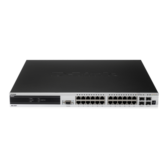
DGS-3600 Series Layer 3 Gigabit Ethernet Managed Switch Figure 1- 6. DGS-3612G LEDs Figure 1- 7. DGS-3612 LEDs Figure 1- 8. DGS-3627 LEDs Figure 1- 9. DGS-3627G LEDs Figure 1- 10. DGS-3650 LEDs Rear Panel Description The rear panels of the DGS-3612, DGS-3612G, DGS-3627, DGS-3627G and the DGS-3650 are described below. -
Page 21: Side Panel Description
DGS-3600 Series Layer 3 Gigabit Ethernet Managed Switch Figure 1- 12. Rear panel view of the DGS-3612G DGS-3627 and DGS-3627G The rear panel of DGS-3627 and DGS-3627G contain an AC power connector, an outlet for an optional external RPS, and three slots for additional 10GE optional modules. - Page 22 DGS-3600 Series Layer 3 Gigabit Ethernet Managed Switch Figure 1- 17. Side Panels of the DGS-3627 Figure 1- 18. Side Panels of the DGS-3627G Figure 1- 19. Side Panels of the DGS-3650...
-
Page 23: 10Ge Uplink Modules
10GE Uplink Modules At the rear of the xStack DGS-3600 Series switches reside optional module slots. This slot may be equipped with the DEM-410X single-port 10GE XFP uplink module, or a DEM-410CX single-port 10GE CX4 uplink module, both sold separately. -
Page 24: Installing The Sfp Ports
Installing the SFP ports The xStack DGS-3600 Series switches are equipped with SFP (Small Form Factor Portable) ports, which are to be used with fiber-optical transceiver cabling in order to uplink various other networking devices for a gigabit link that may span great distances. -
Page 25: Installation
DCE RS-232 console cable • If any item is missing or damaged, please contact your local D-Link Reseller for replacement. Before You Connect to the Network The site where you install the Switch may greatly affect its performance. Please follow these guidelines for setting up the Switch. -
Page 26: Installing The Switch Without The Rack
DGS-3600 Series Layer 3 Gigabit Ethernet Managed Switch Installing the Switch without the Rack When installing the Switch on a desktop or shelf, the rubber feet included with the Switch should first be attached. Attach these cushioning feet on the bottom at each corner of the device. Allow enough ventilation space between the Switch and any other objects in the vicinity. -
Page 27: Power On Ac Power
DGS-3600 Series Layer 3 Gigabit Ethernet Managed Switch Mounting the Switch in a Standard 19" Rack CAUTION: Installing systems in a rack without the front and side stabilizers installed could cause the rack to tip over, potentially resulting in bodily injury under certain circumstances. Therefore, always install the stabilizers before installing components in the rack. -
Page 28: Rps Installation
DGS-3600 Series Layer 3 Gigabit Ethernet Managed Switch RPS Installation The xStack DGS-3600 Series switches are equipped with a redundant power supply feature. Follow the instructions below to connect a RPS power supply (DPS-500) to the DGS-3627/DGS-3627G/DGS-3612G/DGS-3650. The DPS-500 is a redundant power-supply unit designed to conform to the voltage requirements of the switches being supported. - Page 29 DGS-3600 Series Layer 3 Gigabit Ethernet Managed Switch Connect to RPS The DPS-500 is connected to the Master Switch using a 14-pin DC power cable. A standard, three-pronged AC power cable connects the redundant power supply to the main power source.
- Page 30 DGS-3600 Series Layer 3 Gigabit Ethernet Managed Switch DPS-200 The xStack DGS-3612 switch can connect an RPS power supply to the Switch (DPS-200) redundant power-supply unit designed to conform to the voltage requirements of the switches being supported. The DPS-200 is a redundant power-supply unit designed to conform to the voltage requirements of the switches being supported.
- Page 31 DGS-3600 Series Layer 3 Gigabit Ethernet Managed Switch DPS-800 The DPS-800 is a standard-size rack mount (1 standard unit in height) designed to hold up to two DPS-200 redundant power supplies. Figure 2 - 8. Install DPS-200 in DPS-800 The RPS can be mounted in a standard 19"...
-
Page 32: Connecting The Switch
DGS-3600 Series Layer 3 Gigabit Ethernet Managed Switch Section 3 Connecting the Switch Switch to End Node Switch to Hub or Switch Connecting to Network Backbone or Server NOTE: All 10/100/1000Mbps NWay Ethernet ports can support both MDI- II and MDI-X connections. -
Page 33: Switch To Hub Or Switch
DGS-3600 Series Layer 3 Gigabit Ethernet Managed Switch Switch to Hub or Switch These connections can be accomplished in a number of ways using a normal cable. A 10BASE-T hub or switch can be connected to the Switch via a twisted-pair Category 3, 4 or 5 UTP/STP cable. -
Page 34: Connecting To Network Backbone Or Server
DGS-3600 Series Layer 3 Gigabit Ethernet Managed Switch Connecting To Network Backbone or Server The two Mini-GBIC combo ports are ideal for uplinking to a network backbone or server. The copper ports operate at a speed of 1000, 100, or 10Mbps in full duplex mode. The fiber optic ports can operate at 1000Mbps in full duplex mode. Connections to the Gigabit Ethernet ports are made using fiber optic cable or Category 5 copper cable, depending on the type of port. -
Page 35: Introduction To Switch Management
DGS-3600 Series Layer 3 Gigabit Ethernet Managed Switch Section 4 Introduction to Switch Management Management Options Web-based Management Interface SNMP-Based Management Managing User Accounts Command Line Console Interface through the Serial Port Connecting the Console Port (RS-232 DCE) First Time Connecting to the Switch... - Page 36 12. Enter the commands to complete your desired tasks. Many commands require administrator-level access privileges. Read the next section for more information on setting up user accounts. See the xStack DGS-3600 Series CLI Manual on the documentation CD for a list of all commands and additional information on using the CLI.
-
Page 37: First Time Connecting To The Switch
DGS-3600 Series Layer 3 Gigabit Ethernet Managed Switch First Time Connecting to the Switch The Switch supports user-based security that can allow you to prevent unauthorized users from accessing the Switch or changing its settings. This section tells how to log onto the Switch. -
Page 38: Snmp Settings
DGS-3600 Series Layer 3 Gigabit Ethernet Managed Switch After your initial login, define new passwords for both default user names to prevent unauthorized access to the Switch, and record the passwords for future reference. To create an administrator-level account for the Switch, follow these steps: At the CLI login prompt, enter create account admin followed by the <user name>... -
Page 39: Ip Address Assignment
DGS-3600 Series Layer 3 Gigabit Ethernet Managed Switch SNMP v.3 uses a more sophisticated authentication process that is separated into two parts. The first part is to maintain a list of users and their attributes that are allowed to act as SNMP managers. The second part describes what each user on that list can do as an SNMP manager. - Page 40 DGS-3600 Series Layer 3 Gigabit Ethernet Managed Switch The IP address for the Switch must be set before it can be managed with the Web-based manager. The Switch IP address can be automatically set using BOOTP or DHCP protocols, in which case the actual address assigned to the Switch must be known.
-
Page 41: Web-Based Switch Configuration
DGS-3600 Series Layer 3 Gigabit Ethernet Managed Switch Section 5 Web-based Switch Configuration Introduction Login to Web manager Web-Based User Interface Web Pages Introduction All software functions of the Switch can be managed, configured and monitored via the embedded web-based (HTML) interface. -
Page 42: Web-Based User Interface
Area 1 Select the folder or window to be displayed. The folder icons can be opened to display the hyper- linked window buttons and subfolders contained within them. Click the D-Link logo to go to the D- Link website. Area 2 Presents a graphical near real-time image of the front panel of the Switch. -
Page 43: Web Pages
DGS-3600 Series Layer 3 Gigabit Ethernet Managed Switch NOTICE: Any changes made to the Switch configuration during the current session must be saved in the Save Changes window (explained below) or use the command line interface (CLI) command save. -
Page 44: Administration
DGS-3600 Series Layer 3 Gigabit Ethernet Managed Switch Section 6 Administration Device Information (DGS-3600 Web Management Tool) IP Address Stacking Port Configuration User Accounts Port Mirroring System Log System Severity Settings SNTP Settings MAC Notification Settings TFTP Services File System Services... -
Page 45: Device Information
DGS-3600 Series Layer 3 Gigabit Ethernet Managed Switch Device Information This window contains the main settings for all major functions for the Switch and appears automatically when you log on. To return to the Device Information window, click the DGS-... - Page 46 DGS-3600 Series Layer 3 Gigabit Ethernet Managed Switch seconds. The default setting is 300 seconds. IGMP Snooping To enable system-wide IGMP Snooping capability select Enabled. IGMP snooping is Disabled by default. Enabling IGMP snooping allows you to specify use of a multicast router only (see below).
-
Page 47: Ip Address
DGS-3600 Series Layer 3 Gigabit Ethernet Managed Switch 65535) accessed, before it is dropped from the table. The value may be set in the range of 0 to 65535 minutes with a default setting of 20 minutes. DVMRP State The user may globally enable or disable the Distance Vector Multicast Routing Protocol (DVMRP) function by using the pull-down menu. - Page 48 DGS-3600 Series Layer 3 Gigabit Ethernet Managed Switch NOTE: The Switch's factory default IP address is 10.90.90.90 with a subnet mask of 255.0.0.0 and a default gateway of 0.0.0.0. To use the BOOTP or DHCP protocols to assign the Switch an IP address, subnet mask, and default gateway address: Use the Get IP From pull-down menu to choose from BOOTP or DHCP.
-
Page 49: Stacking
Stacking From firmware release v2.00 of this Switch, the xStack DGS-3600 Series now supports switch stacking, where a set of twelve switches can be combined to be managed by one IP address through Telnet, the GUI interface (web), the console port or through SNMP. -
Page 50: Stack Switch Swapping
DGS-3600 Series Layer 3 Gigabit Ethernet Managed Switch Within each of these topologies, each switch plays a role in the Switch stack. These roles can be set by the user per individual Switch, or if desired, can be automatically determined by the Switch stack. Three possible roles exist when stacking with the xStack DGS-3600 Series. -
Page 51: Stacking Mode Settings
This window is found in the Administration folder under the heading Stacking. This window is used to configure stacking parameters associated with all switches in the xStack DGS-3600 Series. The user may configure parameters such as box ID, box priority and pre-assigning model names to switches to be entered into the switch stack. -
Page 52: Ip Interface Setup
DGS-3600 Series Layer 3 Gigabit Ethernet Managed Switch Priority Displays the priority ID of the Switch. The lower the number, the higher the priority. The box (switch) with the lowest priority number in the stack is the Primary Master switch. The Primary Master switch will be used to configure applications of the switch stack. -
Page 53: Port Configuration
DGS-3600 Series Layer 3 Gigabit Ethernet Managed Switch Port Configuration This section contains information for configuring various attributes and properties for individual physical ports, including port speed and flow control. Port Configuration Click Administration > Port Configuration > Port Configuration to display the following window: To configure switch ports: 1. -
Page 54: Port Error Disabled
DGS-3600 Series Layer 3 Gigabit Ethernet Managed Switch The Switch allows the user to configure two types of gigabit connections; 1000M/Full_M and 1000M/Full_S. Gigabit connections only support full duplex connections and take on certain characteristics that are different from the other choices listed. -
Page 55: Port Description
DGS-3600 Series Layer 3 Gigabit Ethernet Managed Switch Port Description The Switch supports a port description feature where the user may name various ports on the Switch. To assign names to various ports, click Administration > Port Configuration > Port Description to view the... - Page 56 DGS-3600 Series Layer 3 Gigabit Ethernet Managed Switch Figure 6- 11. User Account Add Table window Add a new user by typing in a User Name, and New Password and retype the same password in the Confirm New Password.
-
Page 57: Port Mirroring
DGS-3600 Series Layer 3 Gigabit Ethernet Managed Switch Port Mirroring The Switch allows you to copy frames transmitted and received on a port and redirect the copies to another port. You can attach a monitoring device to the mirrored port, such as a sniffer or an RMON probe, to view details about the packets passing through the first port. -
Page 58: System Log
DGS-3600 Series Layer 3 Gigabit Ethernet Managed Switch System Log The System Log folder contains two main windows System Log Host and System Log Save Mode Settings. System Log Host The Switch can send Syslog messages to up to four designated servers using the System Log Server. In the Administration folder, click System Log >... -
Page 59: System Log Save Mode Settings
DGS-3600 Series Layer 3 Gigabit Ethernet Managed Switch kernel messages user-level messages mail system system daemons security/authorization messages messages generated internally by syslog line printer subsystem network news subsystem UUCP subsystem clock daemon security/authorization messages FTP daemon NTP subsystem... -
Page 60: System Severity Settings
DGS-3600 Series Layer 3 Gigabit Ethernet Managed Switch System Severity Settings The Switch can be configured to allow alerts be logged or sent as a trap to an SNMP agent or both. The level at which the alert triggers either a log entry or a trap message can be set as well. Use the System Severity Settings menu to set the criteria for alerts. -
Page 61: Sntp Settings
DGS-3600 Series Layer 3 Gigabit Ethernet Managed Switch SNTP Settings Time Settings To configure the time settings for the Switch, open the Administration folder. Then the SNTP Settings folder and click on the Time Settings link, revealing the following window for the user to configure. -
Page 62: Time Zone And Dst
DGS-3600 Series Layer 3 Gigabit Ethernet Managed Switch Enter the current day, if you would like to update the system clock. Time in HH MM SS Enter the current time in hours, minutes, and seconds. Click Apply to implement changes made. - Page 63 DGS-3600 Series Layer 3 Gigabit Ethernet Managed Switch in +/- HH:MM Mean Time (GMT.) DST Repeating Settings Using repeating mode will enable DST seasonal time adjustment. Repeating mode requires that the DST beginning and ending date be specified using a formula. For example, specify to begin DST on Saturday during the second week of April and end DST on Sunday during the last week of October.
-
Page 64: Mac Notification Settings
DGS-3600 Series Layer 3 Gigabit Ethernet Managed Switch MAC Notification Settings MAC Notification is used to monitor MAC addresses learned and entered into the forwarding database. To globally set MAC notification on the Switch, open the following window by clicking MAC Notification Settings in the Administration folder. - Page 65 DGS-3600 Series Layer 3 Gigabit Ethernet Managed Switch The user also has the option of transferring firmware and configuration files to and from the internal Flash drive, located on the Switch. Using this window, the user can receive a configuration or firmware file from a TFTP server, or transfer that firmware or configuration file to a TFTP server.
-
Page 66: File System Services
DGS-3600 Series Layer 3 Gigabit Ethernet Managed Switch File System Services The Switch contains a 16-megabyte Flash memory where the user may store files for further use on the Switch. The user may place over 200 re-nameable files on the FAT 16 mode Flash memory, of which the user has the option of setting firmware images and configuration files as boot up files, upon the next reboot of the Switch. -
Page 67: Directory
DGS-3600 Series Layer 3 Gigabit Ethernet Managed Switch Directory The Directory window allows users to view files stored in the flash memory of the Switch. In future releases, more than one drive may be located in the Flash drive, but for this release, the only drive located on the Flash memory of the Switch is C:. Therefore, to view files located on C:, the user should enter C: into the Drive ID field and click Find. -
Page 68: Copy
DGS-3600 Series Layer 3 Gigabit Ethernet Managed Switch Figure 6- 25. Rename window Copy This window is used to copy a directory located within the Flash memory of the switch. To view this window, click Administration > File System Services > Copy. Click Copy to initiate copying the file. -
Page 69: Ping Test
DGS-3600 Series Layer 3 Gigabit Ethernet Managed Switch Ping Test Ping is a small program that sends ICMP Echo packets to the IP address you specify. The destination node then responds to or "echoes" the packets sent from the Switch. This is very useful to verify connectivity between the Switch and other nodes on the network. -
Page 70: Ipv6 Ping Test
DGS-3600 Series Layer 3 Gigabit Ethernet Managed Switch IPv6 Ping Test The following window is used to Ping an IPv6 address. To locate this window, open the Administration folder and click Ping Test > IPv6 Ping Test. Figure 6- 28. IPv6 Ping Test window This window allows the following parameters to be configured to ping an IPv6 address. -
Page 71: Ipv6 Neighbor
DGS-3600 Series Layer 3 Gigabit Ethernet Managed Switch IPv6 Neighbor IPv6 neighbors are devices on the link-local network that have been detected as being IPv6 devices. These devices can forward packets and keep track of the reachability of routers, as well as if changes occur within link-layer addresses of nodes on the network or if identical unicast addresses are present on the local link. -
Page 72: Dhcp Auto Configuration Settings
DGS-3600 Series Layer 3 Gigabit Ethernet Managed Switch Figure 6- 30. IPv6 Neighbor Settings – Add window The following fields can be set or viewed: Parameter Description Interface Name Enter the name of the Interface associated with this entry, if any. -
Page 73: Snmp Manager
DGS-3600 Series Layer 3 Gigabit Ethernet Managed Switch SNMP Manager SNMP Settings Simple Network Management Protocol (SNMP) is an OSI Layer 7 (Application Layer) designed specifically for managing and monitoring network devices. SNMP enables network management stations to read and modify the settings of gateways, routers, switches, and other network devices. -
Page 74: Snmp Trap Settings
DGS-3600 Series Layer 3 Gigabit Ethernet Managed Switch SNMP Trap Settings The following window is used to enable and disable trap settings for the SNMP function on the Switch. To view this window for configuration, click Administration > SNMP Manager > SNMP Trap Settings: Figure 6- 32. - Page 75 DGS-3600 Series Layer 3 Gigabit Ethernet Managed Switch Figure 6- 33. SNMP User Table window To delete an existing SNMP User Table entry, click the below the Delete heading corresponding to the entry you wish to delete. To display the detailed entry for a given user, click the View button under the Display heading. This will open the SNMP User Table Display window, as shown below.
- Page 76 DGS-3600 Series Layer 3 Gigabit Ethernet Managed Switch Figure 6- 35. SNMP User Table Configuration window The following parameters can set: Parameter Description User Name Enter an alphanumeric string of up to 32 characters. This is used to identify the SNMP user.
-
Page 77: Snmp View Table
DGS-3600 Series Layer 3 Gigabit Ethernet Managed Switch SNMP View Table This window is used to assign views to community strings that define which MIB objects can be accessed by a remote SNMP manager. To view the SNMP View Table window, open the SNMP Manager folder under Administration and click the SNMP View Table entry. -
Page 78: Snmp Group Table
DGS-3600 Series Layer 3 Gigabit Ethernet Managed Switch SNMP Group Table An SNMP Group created with this table maps SNMP users (identified in the SNMP User Table) to the views created in the previous menu. To view the SNMP Group Table window, open the SNMP Manager folder in the Administration folder and click the SNMP Group Table entry. -
Page 79: Snmp Community Table
DGS-3600 Series Layer 3 Gigabit Ethernet Managed Switch Figure 6- 40. SNMP Group Table Configuration window The following parameters can set: Parameter Description Group Name Type an alphanumeric string of up to 32 characters. This is used to identify the new SNMP group of SNMP users. -
Page 80: Snmp Host Table
DGS-3600 Series Layer 3 Gigabit Ethernet Managed Switch To configure SNMP Community entries, open the SNMP Manager folder, (located in the Administration folder) and click the SNMP Community Table link, which will open the following window: Figure 6- 41. SNMP Community Table window... - Page 81 DGS-3600 Series Layer 3 Gigabit Ethernet Managed Switch Figure 6- 43. SNMP Host Table Configuration window for IPv4 The following parameters can set: Parameter Description Host IPv4 Address Type the IPv4 address of the remote management station that will serve as the SNMP host for the Switch.
-
Page 82: Snmp Engine Id
DGS-3600 Series Layer 3 Gigabit Ethernet Managed Switch level. Community String or Type in the community string or SNMP V3 user name as appropriate. SNMP V3 User Name To implement your new settings, click Apply. To return to the SNMP Host Table window, click the... -
Page 83: Ip-Mac-Port Binding
DGS-3600 Series Layer 3 Gigabit Ethernet Managed Switch IP-MAC-Port Binding The IP network layer uses a four-byte address. The Ethernet link layer uses a six-byte MAC address. Binding these two address types together allows the transmission of data between the layers. The primary purpose of IP-MAC binding is to restrict the access to a switch to a number of authorized users. - Page 84 DGS-3600 Series Layer 3 Gigabit Ethernet Managed Switch Figure 6- 49. Access Rule Display windows for IP MAC Binding NOTE: When configuring the ACL mode function of the IP-MAC binding function, please pay close attention to previously set ACL entries. Since the ACL mode entries will fill the first two available access profiles and access profile IDs denote the ACL priority, the ACL mode entries may take precedence over other configured ACL entries.
-
Page 85: Ip-Mac Binding Port
DGS-3600 Series Layer 3 Gigabit Ethernet Managed Switch IP-MAC Binding Port To enable or disable IP-MAC binding on specific ports, click IP-MAC Binding Port in the IP-MAC-Port Binding folder in the Administration folder to open the IP-MAC Binding Ports Settings window. Select a port or a range of ports with the From and To fields. -
Page 86: Ip-Mac Binding Table
DGS-3600 Series Layer 3 Gigabit Ethernet Managed Switch IP-MAC Binding Table The window shown below can be used to create IP-MAC binding entries. Click IP-MAC Binding Table in the IP-MAC-Port Binding folder in the Administration folder to view the Address Binding ACL Mode Settings window. Enter the IP and MAC addresses of the authorized users in the appropriate fields and click Add. -
Page 87: Ip-Mac Binding Blocked
DGS-3600 Series Layer 3 Gigabit Ethernet Managed Switch ACL – Choosing this entry will allow only packets from the source IP-MAC binding entry created here. All other packets with a different IP address will be discarded by the Switch. This mode can only be used if the ACL Mode has been enabled in the IP-MAC Binding Ports window as seen previously. -
Page 88: Sflow
DGS-3600 Series Layer 3 Gigabit Ethernet Managed Switch sFlow sFlow is a feature on the Switch that allows users to monitor network traffic running through the switch to identify network problems through packet sampling and packet counter information of the Switch. -
Page 89: Sflow Analyzer Settings
DGS-3600 Series Layer 3 Gigabit Ethernet Managed Switch sFlow Version This displays the current sFlow version. sFlow Address This displays the sFlow IP address. sFlow Analyzer Settings The following windows are used to configure the parameters for the remote sFlow Analyzer (collector) that will be used to gather and analyze sFlow Datagrams that originate from the Switch. - Page 90 DGS-3600 Series Layer 3 Gigabit Ethernet Managed Switch Figure 6- 56. sFlow Counter Analyzer – Add window The following fields can be set or modified: Parameter Description Analyzer Server (1- Enter an integer from 1 to 4 to denote the sFlow Analyzer to be added. Up to four entries can be added, but each entry must have its own unique Collector Port.
-
Page 91: Sflow Sampler Settings
DGS-3600 Series Layer 3 Gigabit Ethernet Managed Switch sFlow Sampler Settings This window will allow users to configure the Switch’s settings for taking sample packets from the network, including the sampling rate and the amount of the packet header to be extracted. To configure the settings for the sFlow Sampler, click the Administration link, open the sFlow folder and click sFlow Sampler Settings, which will produce the following window, displaying the parameters for the sFlow Sampler. -
Page 92: Switch Description
DGS-3600 Series Layer 3 Gigabit Ethernet Managed Switch The following fields may be set: Parameter Description From Choose the beginning port of the range of ports to be configured for packet sampling. Choose the ending port of the range of ports to be configured for packet sampling. - Page 93 DGS-3600 Series Layer 3 Gigabit Ethernet Managed Switch Clear All Click this button to reset the information in this window. To add a new sFlow Counter Poller setting, click the Add button in the previous window which will display the following window to be configured: Figure 6- 60.
-
Page 94: Single Ip Management Settings
Single IP Management Settings Single IP Management (SIM) Overview D-Link Single IP Management is a concept that stacks switches together over Ethernet instead of using stacking ports or modules. There are some advantages in implementing the "Single IP Management" feature: 1. -
Page 95: Sim Settings
DGS-3600 Series Layer 3 Gigabit Ethernet Managed Switch The Upgrade to v1.61 To better improve SIM management, the Switch has been upgraded to version 1.61 in this release. Many improvements have been made, including: 1. The Commander Switch (CS) now has the capability to automatically rediscover member switches that have left the SIM group, either through a reboot or web malfunction. -
Page 96: Parameters Description
DGS-3600 Series Layer 3 Gigabit Ethernet Managed Switch Figure 6- 62. SIM Settings window (enabled) If the Switch Administrator wishes to configure the Switch as a Commander Switch (CS), select commander from the Role State field and click Apply. -
Page 97: Topology
DGS-3600 Series Layer 3 Gigabit Ethernet Managed Switch Topology The Topology window will be used to configure and manage the Switch within the SIM group and requires Java script to function properly on your computer. The Java Runtime Environment on your server should initiate and lead you to the topology window, as seen below. - Page 98 DGS-3600 Series Layer 3 Gigabit Ethernet Managed Switch Model Name Displays the full Model Name of the corresponding Switch. To view the Topology Map, click the View menu in the toolbar and then Topology, which will produce the following window.
-
Page 99: Tool Tips
DGS-3600 Series Layer 3 Gigabit Ethernet Managed Switch Unknown device Non-SIM devices Tool Tips In the Topology View window, the mouse plays an important role in configuration and in viewing device information. Setting the mouse cursor over a specific device in the topology window (tool tip) will display the same information about a specific device as the Tree view does. -
Page 100: Group Icon
DGS-3600 Series Layer 3 Gigabit Ethernet Managed Switch Group Icon Figure 6- 67. Right-Clicking a Group Icon The following options may appear for the user to configure: Collapse - To collapse the group that will be represented by a single icon. -
Page 101: Commander Switch Icon
DGS-3600 Series Layer 3 Gigabit Ethernet Managed Switch Commander Switch Icon Figure 6- 69. Right-Clicking a Commander Icon The following options may appear for the user to configure: Collapse - To collapse the group that will be represented by a single icon. -
Page 102: Menu Bar
DGS-3600 Series Layer 3 Gigabit Ethernet Managed Switch Add to group - Add a candidate to a group. Clicking this option will reveal the following window for the user to • enter a password for authentication from the Candidate Switch before being added to the SIM group. Click OK to enter the password or Cancel to exit the window. -
Page 103: Firmware Upgrade
DGS-3600 Series Layer 3 Gigabit Ethernet Managed Switch NOTE: Upon this firmware release, some functions of the SIM can only be configured through the Command Line Interface. See the DGS-3600 Series CLI Manual for more information on SIM and its configurations. -
Page 104: Upload Log File
DGS-3600 Series Layer 3 Gigabit Ethernet Managed Switch Figure 6- 76. Configuration File Backup/Restore window Upload Log File The following window is used to upload log files from SIM member switches to a specified PC. To view this window click Administration >... -
Page 105: L2 Features
DGS-3600 Series Layer 3 Gigabit Ethernet Managed Switch Section 7 L2 Features VLAN Trunking IGMP Snooping MLD Snooping Spanning Tree Forwarding & Filtering LLDP The following section will aid the user in configuring security functions for the Switch. The Switch includes various functions for VLAN, Trunking, IGMP Snooping, Spanning Tree, and Forwarding &... - Page 106 DGS-3600 Series Layer 3 Gigabit Ethernet Managed Switch Notes About VLANs on the Switch No matter what basis is used to uniquely identify end nodes and assign these nodes VLAN membership, packets cannot cross VLANs without a network device performing a routing function between the VLANs.
-
Page 107: Q Vlan Tags
DGS-3600 Series Layer 3 Gigabit Ethernet Managed Switch 802.1Q VLAN Tags The figure below shows the 802.1Q VLAN tag. There are four additional octets inserted after the source MAC address. Their presence is indicated by a value of 0x8100 in the EtherType field. When a packet's EtherType field is equal to 0x8100, the packet carries the IEEE 802.1Q/802.1p tag. -
Page 108: Tagging And Untagging
DGS-3600 Series Layer 3 Gigabit Ethernet Managed Switch Prior to the adoption of 802.1Q VLANs, port-based and MAC-based VLANs were in common use. These VLANs relied upon a Port VLAN ID (PVID) to forward packets. A packet received on a given port would be assigned that port's PVID and then be forwarded to the port that corresponded to the packet's destination address (found in the Switch's forwarding table). -
Page 109: Vlan Segmentation
DGS-3600 Series Layer 3 Gigabit Ethernet Managed Switch NOTE: If no VLANs are configured on the Switch, then all packets will be forwarded to any destination port. Packets with unknown source addresses will be flooded to all ports. Broadcast and multicast packets will also be flooded to all ports. -
Page 110: Static Vlan Entries
DGS-3600 Series Layer 3 Gigabit Ethernet Managed Switch Static VLAN Entries In the L2 Features folder, click VLAN > Static VLAN Entries to open the following window: Figure 7- 5. Current Static VLAN Entries window The Current Static VLAN Entries window lists all previously configured VLANs by VLAN ID and VLAN Name. To delete an existing 802.1Q VLAN, click the corresponding... - Page 111 DGS-3600 Series Layer 3 Gigabit Ethernet Managed Switch NOTE: The current firmware version requires the user to manually configure the PVID for untagged ports or the host may not connect to the Switch correctly. The following fields can then be set in either the Add or Modify 802.1Q Static VLANs windows:...
-
Page 112: Gvrp Settings
DGS-3600 Series Layer 3 Gigabit Ethernet Managed Switch GVRP Settings In the L2 Features folder, open VLAN and click GVRP Settings. The GVRP Settings window, shown below, allows you to determine whether the Switch will share its VLAN configuration information with other GARP VLAN Registration Protocol (GVRP) enabled switches. -
Page 113: Double Vlan
DGS-3600 Series Layer 3 Gigabit Ethernet Managed Switch Double VLAN Double or Q-in-Q VLANs allow network providers to expand their VLAN configurations to place customer VLANs within a larger inclusive VLAN, which adds a new layer to the VLAN configuration. This basically lets large ISP's create L2 Virtual Private Networks and also create transparent LANs for their customers, which will connect two or more customer LAN points without over-complicating configurations on the client's side. -
Page 114: Regulations For Double Vlans
DGS-3600 Series Layer 3 Gigabit Ethernet Managed Switch Regulations for Double VLANs Some rules and regulations apply with the implementation of the Double VLAN procedure. 1. All ports must be configured for the SPVID and its corresponding TPID on the Service Provider’s edge switch. - Page 115 DGS-3600 Series Layer 3 Gigabit Ethernet Managed Switch Figure 7- 10. Double VLAN State Settings window (Enabled) Parameters shown in the previous window are explained below: Parameter Description Double VLAN Use the pull-down menu to enable or disable the Double VLAN function on this Switch. Enabling...
- Page 116 DGS-3600 Series Layer 3 Gigabit Ethernet Managed Switch Access Ports These are the ports that are set as access ports on the Switch. Access ports are for connecting Switch VLANs to customer VLANs. Gigabit ports cannot be configured as access ports.
-
Page 117: Pvid Auto Assign
DGS-3600 Series Layer 3 Gigabit Ethernet Managed Switch Delete Ports – Will allow users to remove ports from the Service Provider VLAN configured, using the Port List field below. Config TPID – Will allow users to configure the Tagged Protocol ID of the Service Provider VLAN, in hex form. - Page 118 DGS-3600 Series Layer 3 Gigabit Ethernet Managed Switch AppleTalk 0x809B RARP 0x8035 SNA over Ethernet2 0x80D5 Table 7- 1. Protocol VLAN and the corresponding protocol value The following windows are used to create Protocol VLAN groups on the switch. The purpose of these Protocol VLAN groups is to identify ingress untagged packets and quickly and accurately send them to their destination.
-
Page 119: Protocol Vlan Group Settings
DGS-3600 Series Layer 3 Gigabit Ethernet Managed Switch Protocol VLAN Group Settings To begin the Protocol Group VLAN configurations, click L2 Features > VLAN > Protocol VLAN > Protocol VLAN Group Settings, which will display the following window. Figure 7- 15. Protocol VLAN Group Settings window Click the Add button to reveal the following window for the user to configure: Figure 7- 16. -
Page 120: Protocol Vlan Port Settings
DGS-3600 Series Layer 3 Gigabit Ethernet Managed Switch Click Apply to implement changes made. Protocol VLAN Port Settings The following window is used to add a Protocol VLAN Group profile to a port or list of ports and adjust the tags for incoming untagged packets before being relayed through the Switch. -
Page 121: Trunking
DGS-3600 Series Layer 3 Gigabit Ethernet Managed Switch Trunking Understanding Port Trunk Groups Port trunk groups are used to combine a number of ports together to make a single high-bandwidth data pipeline. The Switch supports this function on all its 10/100/1000 Ethernet Ports and on all its 10G interfaces. The 10/100/1000 ports support up to 32 port trunk groups with 2 to 8 ports in each group. -
Page 122: Link Aggregation
DGS-3600 Series Layer 3 Gigabit Ethernet Managed Switch Link aggregation allows several ports to be grouped together and to act as a single link. This gives a bandwidth that is a multiple of a single link's bandwidth. Link aggregation is most commonly used to link a bandwidth intensive network device or devices, such as a server, to the backbone of a network. - Page 123 DGS-3600 Series Layer 3 Gigabit Ethernet Managed Switch Figure 7- 20. Link Aggregation Group Configuration window The user-changeable parameters are as follows: Parameter Description Group ID Select an ID number for the group, between 1 and 32. Trunk groups can be toggled between Enabled and Disabled. This is used to turn a port State trunking group on or off.
-
Page 124: Lacp Port Settings
DGS-3600 Series Layer 3 Gigabit Ethernet Managed Switch LACP Port Settings This window is used in conjunction with the Link Aggregation window to create port trunking groups on the Switch. The user may set which ports will be active and passive in processing and sending LACP control frames. - Page 125 DGS-3600 Series Layer 3 Gigabit Ethernet Managed Switch Figure 7- 22. IGMP Snooping Settings window Clicking the Modify button will open the IGMP Snooping Settings – Edit window, shown below: Figure 7- 23. IGMP Snooping Settings – Edit window...
- Page 126 DGS-3600 Series Layer 3 Gigabit Ethernet Managed Switch (1-255) increased packet loss. This entry field allows an entry of 1 to 255. Default = 2. Last Member Query This field specifies the maximum amount of time between group-specific query messages, Interval (1-25 sec) including those sent in response to leave group messages.
-
Page 127: Router Port Settings
DGS-3600 Series Layer 3 Gigabit Ethernet Managed Switch Router Port Settings A static router port is a port that has a multicast router attached to it. Generally, this router would have a connection to a WAN or to the Internet. Establishing a router port will allow multicast packets coming from the router to be propagated through the network, as well as allowing multicast messages (IGMP) coming from the network to be propagated to the router. -
Page 128: Ism Vlan Settings
DGS-3600 Series Layer 3 Gigabit Ethernet Managed Switch The following parameters can be set: Parameter Description VID (VLAN ID) This is the VLAN ID that, along with the VLAN Name, identifies the VLAN where the multicast router is attached. - Page 129 DGS-3600 Series Layer 3 Gigabit Ethernet Managed Switch 6. One Range (and Range Name) of multicast IP addresses can be added to multiple ISM VLANs, yet multiple Ranges can be added to one ISM VLAN. 7. Router ports cannot be deleted if they are the source ports for ISM VLANs.
-
Page 130: Ip Multicast Address Range Settings
DGS-3600 Series Layer 3 Gigabit Ethernet Managed Switch Member Port Enter a port or list of ports to be added to the Multicast VLAN. Member ports will become the untagged members of the multicast VLAN. Source Port Enter a port or list of ports to be added to the Multicast VLAN. Source ports will become the tagged members of the multicast VLAN. -
Page 131: Limited Multicast Address Range Settings
DGS-3600 Series Layer 3 Gigabit Ethernet Managed Switch Limited Multicast Address Range Settings The Limited IP Multicast Range window allows the user to specify which multicast address(es) reports are to be received on specified ports on the Switch. This function will therefore limit the number of reports received and the number of multicast groups configured on the Switch. -
Page 132: Mld Snooping
DGS-3600 Series Layer 3 Gigabit Ethernet Managed Switch MLD Snooping Multicast Listener Discovery (MLD) Snooping is an IPv6 function used similarly to IGMP snooping in IPv4. It is used to discover ports on a VLAN that are requesting multicast data. Instead of flooding all ports on a selected VLAN with multicast traffic, MLD snooping will only forward multicast data to ports that wish to receive this data through the use of queries and reports produced by the requesting ports and the source of the multicast traffic. - Page 133 DGS-3600 Series Layer 3 Gigabit Ethernet Managed Switch Figure 7- 33. MLD Snooping Settings - Edit window The following parameters may be viewed or modified: Parameter Description VLAN ID This is the VLAN ID that, along with the VLAN Name, identifies the VLAN for which to modify the MLD Snooping Settings.
-
Page 134: Mld Router Port Settings
DGS-3600 Series Layer 3 Gigabit Ethernet Managed Switch Done Timer (1-16711450 sec) Specifies the maximum amount of time a router can remain in the Switch after receiving a done message from the group without receiving a node listener report. - Page 135 DGS-3600 Series Layer 3 Gigabit Ethernet Managed Switch Figure 7- 35. Router Port window (Modify) The following parameters can be set: Parameter Description VID (VLAN ID) This is the VLAN ID that, along with the VLAN Name, identifies the VLAN where the MLD multicast router is attached.
-
Page 136: Spanning Tree
STP will be familiar to most networking professionals. However, since 802.1w RSTP and 802.1s MSTP has been recently introduced to D-Link managed Ethernet switches, a brief introduction to the technology is provided below followed by a description of how to set up 802.1D STP, 802.1w RSTP and 802.1s MSTP. -
Page 137: Edge Port
Switch, such as BPDU packets looped back from an unmanaged switch connected to a DGS-3600 Series switch. To maintain the consistency of the throughput, the DGS-3600 Series switch implements the STP Loopback Detection function. -
Page 138: Stp Bridge Global Settings
DGS-3600 Series Layer 3 Gigabit Ethernet Managed Switch Regulations and Restrictions for the Loopback Detection Function All three versions of STP (STP, RSTP and MSTP) can enable this feature. • May be configured globally (STP Global Bridge Settings), or per port (MSTP Port Information). - Page 139 DGS-3600 Series Layer 3 Gigabit Ethernet Managed Switch Figure 7- 38. STP Bridge Global Settings – STP Compatible window NOTE: The Hello Time cannot be longer than the Max. Age. Otherwise, a configuration error will occur. Observe the following formulas when setting the above parameters: Max.
-
Page 140: Mst Configuration Identification
DGS-3600 Series Layer 3 Gigabit Ethernet Managed Switch the LBD Recover Time times out. The Loopback Detection function will only be implemented on one port at a time. The user may enable or disable this function using the pull-down menu. - Page 141 DGS-3600 Series Layer 3 Gigabit Ethernet Managed Switch open a new window for configuring parameters associated with that particular MSTI. VID List This field displays the VLAN IDs associated with the specific MSTI. Clicking the Add button will reveal the following window to configure: Figure 7- 40.
-
Page 142: Mstp Port Information
DGS-3600 Series Layer 3 Gigabit Ethernet Managed Switch VID List (1-4094) This field is used to specify the VID range from configured VLANs set on the Switch. Supported VIDs on the Switch range from ID number 1 to 4094. This field is inoperable when configuring the CIST. -
Page 143: Stp Instance Settings
DGS-3600 Series Layer 3 Gigabit Ethernet Managed Switch Figure 7- 43. MSTP Port Information window To view the MSTI settings for a particular port, select the Port number, located in the top left hand corner of the screen and click Apply. -
Page 144: Stp Port Settings
DGS-3600 Series Layer 3 Gigabit Ethernet Managed Switch Figure 7- 45. STP Instance Settings window The following information is displayed: Parameter Description Displays the instance type(s) currently configured on the Switch. Each instance type is classified Instance Type by a MSTI ID. CIST refers to the default MSTI configuration set on the Switch. - Page 145 DGS-3600 Series Layer 3 Gigabit Ethernet Managed Switch It is advisable to define an STP Group to correspond to a VLAN group of ports. Figure 7- 47. STP Port Settings window The following STP Port Settings fields can be set:...
-
Page 146: Forwarding & Filtering
DGS-3600 Series Layer 3 Gigabit Ethernet Managed Switch value of False indicates that the port cannot have P2P status. Auto allows the port to have P2P status whenever possible and operate as if the P2P status were true. If the port cannot maintain this status, (for example if the port is forced to half-duplex operation) the P2P status changes to operate as if the P2P value were False. -
Page 147: Multicast Forwarding
DGS-3600 Series Layer 3 Gigabit Ethernet Managed Switch Multicast Forwarding The following window is used to set up multicast forwarding on the Switch. Open the Forwarding & Filtering folder located in L2 Features, and click on the Multicast Forwarding link to see the entry window below: Figure 7- 49. -
Page 148: Multicast Filtering Mode
DGS-3600 Series Layer 3 Gigabit Ethernet Managed Switch Multicast Filtering Mode Open the Forwarding & Filtering folder and click the Multicast Filtering Mode link to see the entry window below: Figure 7- 51. Multicast Filtering Mode Settings window The following parameters can be set:... -
Page 149: Lldp Global Settings
DGS-3600 Series Layer 3 Gigabit Ethernet Managed Switch LLDP allows the transmitter and the receiver to be separately enabled, making it possible to configure an implementation to restrict the local LLDP agent either to transmit only or receive only, or to allow the local LLDP agent to both transmit and receive... -
Page 150: Basic Lldp Port Settings
DGS-3600 Series Layer 3 Gigabit Ethernet Managed Switch Basic LLDP Port Settings The following window is used to set up LLDP on individual port(s) on the Switch. Open LLDP in the L2 Features folder and click the Basic LLDP Port Settings link. -
Page 151: 802.1 Extension Lldp Port Settings
DGS-3600 Series Layer 3 Gigabit Ethernet Managed Switch Admin Status Use the drop-down menu to choose: TX_Only, RX_Only, TX_and_RX, or Disabled. Port Description Use the drop-down menu to toggle Port Description between Enabled and Disabled. System Name Use the drop-down menu to toggle System Name between Enabled and Disabled. -
Page 152: Extension Lldp Port Settings
DGS-3600 Series Layer 3 Gigabit Ethernet Managed Switch The following parameters can be set or displayed: Parameter Description Unit Select the desired stacking unit, if applicable. From/To Select a port or group of ports using the pull-down menus. Port VLAN ID Use the drop-down menu to toggle Port VLAN ID between Enabled and Disabled. - Page 153 DGS-3600 Series Layer 3 Gigabit Ethernet Managed Switch Figure 7- 55. 802.3 Extension LLDP Port Settings Table window The following parameters can be set or displayed: Parameter Description Unit Select the desired stacking unit, if applicable. From/To Select a port or group of ports using the pull-down menus.
-
Page 154: Lldp Management Address Settings
DGS-3600 Series Layer 3 Gigabit Ethernet Managed Switch LLDP Management Address Settings The following window is used to set up LLDP management address settings on the Switch. Open LLDP in the L2 Features folder and click the LLDP Management Address Settings link. -
Page 155: Lldp Statistics
DGS-3600 Series Layer 3 Gigabit Ethernet Managed Switch LLDP Statistics The following window is used to display LLDP statistics. Open LLDP in the L2 Features folder and click the LLDP Statistics link. Figure 7- 57. LLDP Statistics System window... -
Page 156: Lldp Management Address Table
DGS-3600 Series Layer 3 Gigabit Ethernet Managed Switch LLDP Management Address Table The following window is used to make entries to and display the LLDP Management Address Table. Open LLDP in the L2 Features folder and click the LLDP Management Address Table link. -
Page 157: Lldp Remote Port Table
DGS-3600 Series Layer 3 Gigabit Ethernet Managed Switch LLDP Remote Port Table The following window is used to display the LLDP Remote Port Brief Table. Open LLDP in the L2 Features folder and click the LLDP Remote Port Table link. -
Page 158: L3 Features
DGS-3600 Series Layer 3 Gigabit Ethernet Managed Switch Section 8 L3 Features Interface Settings MD5 Key Settings Route Redistribution Settings Static/Default Route Settings Route Preference Settings Static ARP Settings Gratuitous ARP Settings Policy Route Settings OSPF DCHP/BOOTP Relay DHCP Server... -
Page 159: Packet Format
DGS-3600 Series Layer 3 Gigabit Ethernet Managed Switch anycast address has been added, which will send packets to the closest node that is a part of a group of nodes, thereby eliminating a specified device for a particular group. -
Page 160: Extension Headers
DGS-3600 Series Layer 3 Gigabit Ethernet Managed Switch Next Header – This 8-bit field is used to identify the header immediately following the IPv6 header. When this field is set after the hop by-hop header, it defines the extension header that will appear after the destination address. Each extension header must be preceded by a Next Header field. -
Page 161: Address Format
DGS-3600 Series Layer 3 Gigabit Ethernet Managed Switch Once all parts of the fragmented packet reach its destination, they are reassembled using the Fragment Identification value, provided that the source and destination addresses are identical. Address Format To address the problem of finding a larger pool of IP addresses for IPv6, the size and format of the IPv4 format needed to be changed. -
Page 162: Neighbor Discovery
DGS-3600 Series Layer 3 Gigabit Ethernet Managed Switch statically or dynamically assigned to an interface, nor should it be the destination address of an IPv6 packet, or located within the routing header. The second type of special address is the loopback address which is represented by 0:0:0:0:0:0:0:1, or ::1 in its compressed form. -
Page 163: Assigning Ip Addresses
DGS-3600 Series Layer 3 Gigabit Ethernet Managed Switch Duplicate Address Detection (DAD) DAD messages are used to specify that there is more than one node on a local link possessing the same IP address. IPv6 addresses are only leased for a defined period of time. When that time expires, the address will become invalid and another address must be addressed to the node. -
Page 164: Interface Settings
The IP Address may initially be set using the console interface prior to connecting to it through the Ethernet. If the Switch IP address has not yet been changed, read the introduction of the xStack DGS-3600 Series CLI Manual or return to Section 4 of this manual for more information. -
Page 165: Ipv6 Interface Settings
DGS-3600 Series Layer 3 Gigabit Ethernet Managed Switch Figure 8- 3. IPv4 Interface Settings – Edit window Enter a name for the new interface to be added in the Interface Name field (if editing an IP interface, the Interface Name will already be in the top field as seen in the window above). - Page 166 DGS-3600 Series Layer 3 Gigabit Ethernet Managed Switch Figure 8- 4. IPv6 Interface Settings window To add a new IPv6 interface, click the Add button, which will display the following window. Figure 8- 5. IPv6 Interface Settings – Add window To add an Interface, enter an Interface Name in the field provided, along with a corresponding VLAN Name, set the Interface Admin.
- Page 167 DGS-3600 Series Layer 3 Gigabit Ethernet Managed Switch The following fields may be viewed or modified. Click Apply to set changes made. Parameter Description Interface Name This field displays the name for the IP interface or is used to add a new interface or change an existing interface name.
-
Page 168: Md5 Key Settings
DGS-3600 Series Layer 3 Gigabit Ethernet Managed Switch RA Router Lifetime This time represents the validity of this interface to be the default router for the link-local network. A value of 0 represents that this Switch should not be recognized as the default router for this link-local network. -
Page 169: Route Redistribution Settings
DGS-3600 Series Layer 3 Gigabit Ethernet Managed Switch Key ID (1-255) A number from 1 to 255 used to identify the MD5 Key. A alphanumeric string of between 1 and 16 case-sensitive characters used to generate the Message Digest which is in turn, used to authenticate OSPF packets within the OSPF routing domain. -
Page 170: Static/Default Route Settings
DGS-3600 Series Layer 3 Gigabit Ethernet Managed Switch Static/Default Route Settings The Switch supports static routing for IPv4 and IPv6 formatted addressing. Users can create up to 256 static route entries for IPv4 and IPv6 combined. For IPv4 static routes, once a static route has been set, the Switch will send an ARP request packet to the next hop router that has been set by the user. -
Page 171: Ipv6 Static/Default Route Settings
DGS-3600 Series Layer 3 Gigabit Ethernet Managed Switch Figure 8- 10. IPv4 Static/Default Route Settings – Add window The following fields can be set: Parameter Description IP Address Allows the entry of an IP address that will be a static entry into the Switch’s Routing Table. - Page 172 DGS-3600 Series Layer 3 Gigabit Ethernet Managed Switch Next Hop Address The corresponding IPv6 address for the next hop Gateway address in IPv6 format. Metric (1-65535) The metric of the IPv6 interface entered into the table representing the number of routers between the Switch and the IPv6 address above.
-
Page 173: Route Preference Settings
DGS-3600 Series Layer 3 Gigabit Ethernet Managed Switch Route Preference Settings Route Preference is a way for routers to select the best path when there are two or more different routes to the same destination from two different routing protocols. The majority of routing protocols are not compatible when used in conjunction with each other. - Page 174 DGS-3600 Series Layer 3 Gigabit Ethernet Managed Switch Figure 8- 13. Route Preference Settings window The following fields can be viewed or set: Parameter Description RIP (1-999) Enter a value between 1 and 999 to set the route preference for RIP. The lower the value, the higher the chance the specified protocol will be chosen as the best path for routing packets.
-
Page 175: Static Arp Settings
DGS-3600 Series Layer 3 Gigabit Ethernet Managed Switch Static ARP Settings The Address Resolution Protocol (ARP) is a TCP/IP protocol that converts IP addresses into physical addresses. This table allows network managers to view, define, modify and delete ARP information for specific devices. -
Page 176: Gratuitous Arp Settings
DGS-3600 Series Layer 3 Gigabit Ethernet Managed Switch Gratuitous ARP Settings An ARP announcement (also known as Gratuitous ARP) is a packet (usually an ARP Request) containing a valid SHA and SPA for the host which sent it, with TPA equal to SPA. Such a request is not intended to solicit a reply, but merely updates the ARP caches of other hosts which receive the packet. - Page 177 DGS-3600 Series Layer 3 Gigabit Ethernet Managed Switch Gratuitous ARP The switch can trap and log IP conflict events to inform the administrator. By default, trap is Trap & Log Disabled and event log is Enabled. Gratuitous ARP This is used to configure the interval for the periodical sending of gratuitous ARP request Periodical Send packets.
-
Page 178: Policy Route Settings
DGS-3600 Series Layer 3 Gigabit Ethernet Managed Switch Policy Route Settings Policy Based routing is a method used by the Switch to give specified devices a cleaner path to the Internet. Used in conjunction with the Access Profile feature, the Switch... - Page 179 DGS-3600 Series Layer 3 Gigabit Ethernet Managed Switch Figure 8- 21. Policy Routing – Add window Adjust the following parameters and click Apply to set the new Policy Route, which will be displayed in the Policy Routing Settings window. Click Show All Policy Route Entries to return to the Policy Routing Settings window.
-
Page 180: Rip
DGS-3600 Series Layer 3 Gigabit Ethernet Managed Switch The Routing Information Protocol is a distance-vector routing protocol. There are two types of network devices running RIP - active and passive. Active devices advertise their routes to others through RIP messages, while passive devices listen to these messages. -
Page 181: Rip Global Settings
DGS-3600 Series Layer 3 Gigabit Ethernet Managed Switch RIP 1 Message RIP is not limited to TCP/IP. Its address format can support up to 14 octets (when using IP, the remaining 10 octets must be zeros). Other network protocol suites can be specified in the Family of Source Network field (IP has a value of 2). This will determine how the address field is interpreted. -
Page 182: Rip Interface Settings
DGS-3600 Series Layer 3 Gigabit Ethernet Managed Switch RIP Interface Settings RIP settings are configured for each IP interface on the Switch. Click the RIP Interface Settings link in the RIP folder. The window appears in table form listing settings for IP interfaces currently on the Switch. To configure RIP settings for an individual interface, click on the hyperlinked Interface Name. -
Page 183: Ospf
DGS-3600 Series Layer 3 Gigabit Ethernet Managed Switch Interface Metric A read only field that denotes the Metric value of the current IP Interface setting. Click Apply to implement changes made. OSPF The Open Shortest Path First (OSPF) routing protocol uses a link-state algorithm to determine routes to network destinations. A “link”... - Page 184 DGS-3600 Series Layer 3 Gigabit Ethernet Managed Switch Figure 8- 25. Constructing a Shortest Path Tree Router A 128.213.0.0 Router B Router C 192.213.11.0 Router D 222.211.10.0 Figure 8- 26. Constructing a Shortest Path Tree The diagram above shows the network from the viewpoint of Router A. Router A can reach 192.213.11.0 through Router B with a cost of 10 + 5 = 15.
- Page 185 DGS-3600 Series Layer 3 Gigabit Ethernet Managed Switch Router A 128.213.0.0 Router B Router C 192.213.11.0 222.211.10.0 Figure 8- 27. Constructing a Shortest Path Tree - Completed Note that this shortest path tree is only from the viewpoint of Router A. The cost of the link from Router B to Router A, for instance is not important to constructing Router A’s shortest path tree, but is very important when Router B is constructing its...
-
Page 186: Ospf Authentication
DGS-3600 Series Layer 3 Gigabit Ethernet Managed Switch network. Border Routers also have the responsibility of distributing routing information from the Autonomous System Border Router in order for routers in the network to get and maintain routes to other Autonomous Systems. -
Page 187: Designated Router Election
DGS-3600 Series Layer 3 Gigabit Ethernet Managed Switch Authentication − OSPF allows for the configuration of a password for a specific area. Two routers on the same • segment and belonging to the same area must also have the same OSPF password before they can become neighbors. - Page 188 DGS-3600 Series Layer 3 Gigabit Ethernet Managed Switch Database Description packet • Link-State Request packet • Link-State Update packet • Link-State Acknowledgment packet • OSPF Packet Header Every OSPF packet is preceded by a common 24-byte header. This header contains the information necessary for a receiving router to determine if the packet should be accepted for further processing.
- Page 189 DGS-3600 Series Layer 3 Gigabit Ethernet Managed Switch Hello Packet Version No. Packet Length Router ID Area ID Checksum Authentication Type Authentication Authentication Network Mask Hello Interval Options Router Priority Router Dead Interval Designated Router Backup Designated Router Neighbor Figure 8- 29.
- Page 190 DGS-3600 Series Layer 3 Gigabit Ethernet Managed Switch Database Description Packet Packet Length Version No. Router ID Area ID Checksum Authentication Type Authentication Authentication Reserved I M MS Reserved Options DD Sequence No. Link-State Advertisement Header ... Figure 8- 30. Database Description Packet...
- Page 191 DGS-3600 Series Layer 3 Gigabit Ethernet Managed Switch Link-State Request Packet Packet Length Version No. Router ID Area ID Checksum Authentication Type Authentication Authentication Link-State Type Link-State ID Advertising Router Figure 8- 31. Link-State Request Packet Each advertisement requested is specified by its Link-State Type, Link-State ID, and Advertising Router. This uniquely identifies the advertisement, but not its instance.
- Page 192 DGS-3600 Series Layer 3 Gigabit Ethernet Managed Switch Depending on the state of the sending interface and the source of the advertisements being acknowledged, a Link-State Acknowledgment packet is sent either to the multicast address AllSPFRouters, to the multicast address AllDRouters, or as a unicast packet.
-
Page 193: Router Links Advertisements
DGS-3600 Series Layer 3 Gigabit Ethernet Managed Switch Link-State Advertisement Header Link-State Age Options Link-State Type Link-State ID Advertising Router Link-State Sequence Number Link-State Checksum Length Figure 8- 34. Link State Advertisement Header Field Description Link State Age The time is seconds since the link state advertisement was originated. - Page 194 DGS-3600 Series Layer 3 Gigabit Ethernet Managed Switch Routers Links Advertisements Link-State Age Options Link-State Type Link-State ID Advertising Router Link-State Sequence Number Link-State Checksum Length Reserved Reserved Number of Links Link ID Link Data Type No. Of TOS...
-
Page 195: Network Links Advertisements
DGS-3600 Series Layer 3 Gigabit Ethernet Managed Switch Link ID Identifies the object that this router link connects to. Value depends on the link’s Type. When connecting to an object that also originates a link state advertisement (i.e. another router or a transit network) the Link ID is equal to the neighboring advertisement’s Link... -
Page 196: Summary Link Advertisements
DGS-3600 Series Layer 3 Gigabit Ethernet Managed Switch Field Description Network Mask The IP address mask for the network. Attached Router The Router IDs of each of the routers attached to the network. Only those routers that are fully adjacent to the Designated Router (DR) are listed. - Page 197 DGS-3600 Series Layer 3 Gigabit Ethernet Managed Switch when no specific route exists to the destination. When describing a default route, the Link State ID is always set with the Default Destination address (0.0.0.0) and the Network Mask is set to 0.0.0.0.
- Page 198 DGS-3600 Series Layer 3 Gigabit Ethernet Managed Switch Figure 8- 39. NSSA Area example The NSSA ASBR (Not So Stubby Area Autonomous System Border Router) is receiving External Route information and translating it as an LSA Type-7 packet that will be distributed ONLY to switches within the NSSA (Area 2 in the example above).
- Page 199 DGS-3600 Series Layer 3 Gigabit Ethernet Managed Switch Field Description Link State This field will hold information concerning information regarding the LS Checksum, Packet Header length, LS sequence number, Advertising Router, Link State ID, LS age, the packet type (Type-7), and the options field. The Options byte contains information regarding the N-Bit and the P-Bit, which will be described later in this section.
-
Page 200: Ospf Global Settings
DGS-3600 Series Layer 3 Gigabit Ethernet Managed Switch OSPF Global Settings This window allows OSPF to be enabled or disabled on the Switch − without changing the Switch’s OSPF configuration. To view the following window, click L3 Features > OSPF > OSPF Global Settings. To enable OSPF, first supply an OSPF Route ID (see below), select Enabled from the State drop-down menu and click the Apply button. - Page 201 DGS-3600 Series Layer 3 Gigabit Ethernet Managed Switch To remove an Area ID configuration set, simply click in the Delete column for the configuration. To change an existing set in the list, type the Area ID of the set you want to change, make the changes and click the Add/Modify button.
-
Page 202: Ospf Interface Settings
DGS-3600 Series Layer 3 Gigabit Ethernet Managed Switch OSPF Interface Settings To set up OSPF interfaces, click L3 Features > OSPF > OSPF Interface Settings to view OSPF settings for existing IP interfaces. If there are no IP interfaces configured (besides the default System interface), only the System interface settings will appear listed. - Page 203 DGS-3600 Series Layer 3 Gigabit Ethernet Managed Switch Router Priority (0- Allows the entry of a number between 0 and 255 representing the OSPF priority of the 255) selected area. If a Router Priority of 0 is selected, the Switch cannot be elected as the Designated Router for the network.
-
Page 204: Ospf Virtual Link Settings
DGS-3600 Series Layer 3 Gigabit Ethernet Managed Switch OSPF Virtual Link Settings Click the OSPF Virtual Interface Settings link in the OSPF folder to view the current OSPF Virtual Interface Settings. There are not virtual interface settings configured by default, so the first time this table is viewed there will be not interfaces listed. To add a new OSPF virtual interface configuration set to the table, click the Add button. -
Page 205: Ospf Area Aggregation Settings
DGS-3600 Series Layer 3 Gigabit Ethernet Managed Switch MD5 Key Settings window. Transmit Delay The number of seconds required to transmit a link state update over this virtual link. Transit delay takes into account transmission and propagation delays. This field is fixed at 1 second. -
Page 206: Ospf Host Route Settings
DGS-3600 Series Layer 3 Gigabit Ethernet Managed Switch Parameter Description Allows the entry the OSPF Area ID for which the routing information will be aggregated. This Area ID Area ID must be previously defined on the Switch. Network Number Sometimes called the Network Address. -
Page 207: Dhcp/Bootp Relay
DGS-3600 Series Layer 3 Gigabit Ethernet Managed Switch Host Address The IP address of the OSPF host. Metric A value between 1 and 65535 that will be advertised for the route. Area ID A 32-bit number in the form of an IP address (xxx.xxx.xxx.xxx) that uniquely identifies the OSPF area in the OSPF domain. - Page 208 DGS-3600 Series Layer 3 Gigabit Ethernet Managed Switch option 82 information has been added to the packet it is sent on to the DHCP server. When the DHCP server receives the packet, if the server is capable of option 82, it can implement policies like restricting the number of IP addresses that can be assigned to a single remote ID or circuit ID.
-
Page 209: Dhcp/Bootp Relay Interface Settings
DGS-3600 Series Layer 3 Gigabit Ethernet Managed Switch 1 byte 1 byte 1 byte 1 byte 2 bytes 1 byte 1 byte Sub-option type b. Length Circuit ID type d. Length VLAN: the incoming VLAN ID of DHCP client packet. -
Page 210: Dhcp Server
DGS-3600 Series Layer 3 Gigabit Ethernet Managed Switch DHCP Server For this release, the Switch now has the capability to act as a DHCP server to devices within its locally attached network. DHCP, or Dynamic Host Configuration Protocol, allows the switch to delegate IP addresses, subnet masks, default gateways and other IP parameters to devices that request this information. -
Page 211: Dhcp Server Exclude Address Settings
DGS-3600 Series Layer 3 Gigabit Ethernet Managed Switch DHCP Server Exclude Address Settings The following window will allow the user to set an IP address, or a range of IP addresses that are NOT to be included in the range of IP addresses that the Switch will allot to clients requesting DHCP service. - Page 212 DGS-3600 Series Layer 3 Gigabit Ethernet Managed Switch Figure 8- 58. Config DHCP Pool window The following parameters may be configured or viewed. Parameter Description Pool Name Denotes the name of the DHCP pool for which you are currently adjusting the parameters.
- Page 213 DGS-3600 Series Layer 3 Gigabit Ethernet Managed Switch default router must be on the same subnet as the DHCP client. Pool Lease Using this field, the user can specify the lease time for the DHCP client. This time represents the amount of time that the allotted address is valid on the local network.
-
Page 214: Dhcp Server Dynamic Binding
DGS-3600 Series Layer 3 Gigabit Ethernet Managed Switch DHCP Server Dynamic Binding The following window will allow users to view dynamically bound IP addresses of the DHCP server. These IP addresses are ones that were allotted to clients on the local network and are now bound to the device stated by its MAC address. To view this window, click L3 Features >... - Page 215 DGS-3600 Series Layer 3 Gigabit Ethernet Managed Switch Figure 8- 61. DHCP Server Manual Binding Table window Users may view statically bound DHCP entries within a DHCP pool by entering the Pool Name and clicking Find. Results will be displayed in the window above.
-
Page 216: Dns Relay
DGS-3600 Series Layer 3 Gigabit Ethernet Managed Switch DNS Relay Computer users usually prefer to use text names for computers for which they may want to open a connection. Computers themselves, require 32 bit IP addresses. Somewhere, a database of network devices’ text names and their corresponding IP addresses must be maintained. -
Page 217: Dns Relay Static Settings
DGS-3600 Series Layer 3 Gigabit Ethernet Managed Switch Secondary Name Allows the entry of the IP address of a secondary domain name server (DNS). Server DNSR Cache Status This can be toggled between Disabled and Enabled. This determines if a DNS cache will be enabled on the Switch. -
Page 218: Vrrp
DGS-3600 Series Layer 3 Gigabit Ethernet Managed Switch VRRP VRRP or Virtual Routing Redundancy Protocol is a function on the Switch that dynamically assigns responsibility for a virtual router to one of the VRRP routers on a LAN. The VRRP router that controls the IP address associated with a virtual router is called the Master, and will forward packets sent to this IP address. - Page 219 DGS-3600 Series Layer 3 Gigabit Ethernet Managed Switch Interface Name - An IP interface name that has been enabled for VRRP. This entry must have been previously set in the IP Interfaces table. Virtual IP Address The IP address of the Virtual router configured on the Switch.
- Page 220 DGS-3600 Series Layer 3 Gigabit Ethernet Managed Switch priority will increase the probability that this router will become the Master router of the group. A lower priority will increase the probability that this router will become the backup router. VRRP routers that are assigned the same priority value will elect the highest physical IP address as the Master router.
- Page 221 DGS-3600 Series Layer 3 Gigabit Ethernet Managed Switch This window displays the following information: Parameter Description Interface Name An IP interface name that has been enabled for VRRP. This entry must have been previously set in the IP Interface Settings table.
- Page 222 DGS-3600 Series Layer 3 Gigabit Ethernet Managed Switch Figure 8- 6 . VRRP Virtual Router Settings window Click the hyperlink VRID / Interface Name that you want to edit to display the following window: Figure 8- 7 . VRRP Virtual Router Settings window...
- Page 223 DGS-3600 Series Layer 3 Gigabit Ethernet Managed Switch Preempt Mode This entry will determine the behavior of backup routers within the VRRP group by controlling whether a higher priority backup router will preempt a lower priority Master router. A True entry, along with having the backup router’s priority set higher than the masters priority, will set the backup router as the Master router.
- Page 224 DGS-3600 Series Layer 3 Gigabit Ethernet Managed Switch...
-
Page 225: Vrrp Authentication Settings
DGS-3600 Series Layer 3 Gigabit Ethernet Managed Switch VRRP Authentication Settings This window is used to set the authentication for each Interface configured for VRRP. This authentication is used to identify incoming message packets received by a router. If the authentication is not consistent with incoming packets, they will be discarded. -
Page 226: Ip Multicast Routing Protocol
DGS-3600 Series Layer 3 Gigabit Ethernet Managed Switch IP Multicast Routing Protocol The functions supporting IP multicasting are added under the IP Multicast Routing Protocol folder, from the L3 Features folder. IGMP, DVMRP, and PIM-DM/SM/SM-DM can be enabled or disabled on the Switch without changing the individual protocol’s configuration by using the DGS-3600 Web Management Tool. -
Page 227: Igmp Version
DGS-3600 Series Layer 3 Gigabit Ethernet Managed Switch The states a computer will go through to join or to leave a multicast group are shown below: Figure 8- 7 . IGMP State Transitions IGMP Version 3 The current release of the Switch now implements IGMPv3. Improvements of IGMPv3 over version 2 include: The introduction of the SSM or Source Specific Multicast. -
Page 228: Igmp Interface Settings
DGS-3600 Series Layer 3 Gigabit Ethernet Managed Switch Timers As previously mentioned, IGMPv3 incorporates filters to include or exclude sources. These filters are kept updated using timers. IGMPv3 utilizes two types of timers, one for the group and one for the source. The purpose of the filter mode is to reduce the reception state of a multicast group so that all members of the multicast group are satisfied. - Page 229 DGS-3600 Series Layer 3 Gigabit Ethernet Managed Switch Figure 8- 7 . IGMP Interface Settings – Edit window This window allows the configuration of IGMP for each IP interface configured on the Switch. IGMP can be configured as Version 1, 2 or 3 by toggling the Version field using the pull-down menu. The length of time between queries can be varied by entering a value between 1 and 31,744 seconds in the Query Interval field.
-
Page 230: Dvmrp Global Settings
DGS-3600 Series Layer 3 Gigabit Ethernet Managed Switch DVMRP Interface Configuration The Distance Vector Multicast Routing Protocol (DVMRP) is a hop-based method of building multicast delivery trees from multicast sources to all nodes of a network. Because the delivery trees are ‘pruned’ and ‘shortest path’, DVMRP is relatively efficient. - Page 231 DGS-3600 Series Layer 3 Gigabit Ethernet Managed Switch Figure 8- 7 . DVMRP Interface Settings - Edit window The following fields can be set: Parameter Description Interface Name Displays the name of the IP interface for which DVMRP is to be configured. This must be a previously defined IP interface.
- Page 232 DGS-3600 Series Layer 3 Gigabit Ethernet Managed Switch mechanism can also determine the RP. Multiple Candidate BSRs (C-BSR) can be set on the network but only one BSR will be elected to process RP information. If it is not explicitly apparent which C-BSR is to be the BSR, all C-BSRs will emit Boot Strap Messages (BSM) out on the PIM-SM enabled network to determine which C-BSR has the higher priority and once determined, will be elected as the BSR.
-
Page 233: Pim Global Settings
DGS-3600 Series Layer 3 Gigabit Ethernet Managed Switch interface list if RP is not found. In other words, the PIM Sparse-Dense mode is treated in either the sparse mode or dense mode of the operation; it depends on which mode the multicast group operates. When an interface receives multicast traffic, if there is a known RP for the group, then the current operation mode on the interface is sparse mode, otherwise the current operation mode on the interface will be dense mode. -
Page 234: Pim Interface Settings
DGS-3600 Series Layer 3 Gigabit Ethernet Managed Switch NOTE: The Probe time value must be less than half of the Register Suppression Time value. If not, the administrator will be presented with an error message after clicking Apply. PIM Interface Settings To configure the settings for the PIM Protocol per IP interface, go to L3 Features >... -
Page 235: Pim Candidate Bsr Settings
DGS-3600 Series Layer 3 Gigabit Ethernet Managed Switch Join/Prune Interval This field will set the interval time between the sending of Join/Prune packets stating which (1-18724 sec) multicast groups are to join the PIM enabled network and which are to be removed or “pruned”... -
Page 236: Pim Candidate Rp Settings
DGS-3600 Series Layer 3 Gigabit Ethernet Managed Switch Figure 8- 8 . PIM Candidate BSR Settings – Edit window The following fields can be viewed or set: Parameter Description This read-only field denotes the IP Interface Name to be edited for its C-BSR priority. -
Page 237: Pim Static Rp Settings
DGS-3600 Series Layer 3 Gigabit Ethernet Managed Switch Candidate RP Enter a priority value to determine which CRP will become the RP for the distribution tree. Priority (0-255) This priority value will be included in the router’s CRP advertisements. A lower value means a higher priority, yet, if there is a tie for the highest priority, the router having the higher IP address will become the RP. -
Page 238: Pim Register Checksum Settings
DGS-3600 Series Layer 3 Gigabit Ethernet Managed Switch Group Address Enter the multicast group address for this Static RP. This address must be a class D address. Group Mask Enter the mask for the multicast group address stated above. -
Page 239: Qos
DGS-3600 Series Layer 3 Gigabit Ethernet Managed Switch Section 9 Bandwidth Control QoS Scheduling Mechanism QoS Output Scheduling 802.1p Default Priority 802.1p User Priority The Switch supports 802.1p priority queuing Quality of Service. The following section discusses the implementation of QoS (Quality of Service) and benefits of using 802.1p priority queuing. -
Page 240: Understanding Qos
DGS-3600 Series Layer 3 Gigabit Ethernet Managed Switch administrator instructs the Switch to examine packets for this tag, acquires the tagged packets and maps them to a class queue on the Switch. Then in turn, the administrator will set a priority for this queue so that will be emptied before any other packet is forwarded. -
Page 241: Bandwidth Control
DGS-3600 Series Layer 3 Gigabit Ethernet Managed Switch Bandwidth Control The bandwidth control settings are used to place a ceiling on the transmitting and receiving data rates for any selected port. In the QoS folder, click Bandwidth Control, to view the window shown below. -
Page 242: Qos Scheduling Mechanism
DGS-3600 Series Layer 3 Gigabit Ethernet Managed Switch QoS Scheduling Mechanism Changing the output scheduling used for the hardware queues in the Switch can customize QoS. As with any changes to QoS implementation, careful consideration should be given to how network traffic in lower priority queues is affected. Changes in scheduling may result in unacceptable levels of packet loss or significant transmission delay. -
Page 243: Configuring The Combination Queue
DGS-3600 Series Layer 3 Gigabit Ethernet Managed Switch The following values may be assigned to the QoS classes to set the scheduling. Parameter Description Max. Packets Specifies the maximum number of packets the above specified hardware priority class of service will be allowed to transmit before allowing the next lowest priority queue to transmit its packets. -
Page 244: 802.1P Default Priority
DGS-3600 Series Layer 3 Gigabit Ethernet Managed Switch 802.1p Default Priority The Switch allows the assignment of a default 802.1p priority to each port on the Switch. In the QoS folder, click 802.1p Default Priority, to view the window shown adjacent. - Page 245 DGS-3600 Series Layer 3 Gigabit Ethernet Managed Switch Figure 9- 7. 802.1p User Priority window Once a priority to the port groups on the Switch has been assigned, users can then assign this Class to each of the eight levels of...
-
Page 246: Acl
DGS-3600 Series Layer 3 Gigabit Ethernet Managed Switch Section 10 Time Range Access Profile Table ACL Flow Meter CPU Interface Filtering Time Range This window is used in conjunction with the Access Profile feature to determine a starting point and an ending point, based on days of the week, when an Access Profile configuration will be enabled on the Switch. -
Page 247: Access Profile Table
DGS-3600 Series Layer 3 Gigabit Ethernet Managed Switch Click Apply to implement changes made. Currently configured entries will be displayed in the Time Range Information table in the bottom half of the window shown above. Access profiles allow users to establish criteria to determine whether or not the Switch will forward packets based on the information contained in each packet's header. - Page 248 DGS-3600 Series Layer 3 Gigabit Ethernet Managed Switch header. Select IP to instruct the Switch to examine the IP address in each frame's • header. Select Packet Content Mask to specify a mask to hide the content of the packet •...
- Page 249 DGS-3600 Series Layer 3 Gigabit Ethernet Managed Switch header. Select IP to instruct the Switch to examine the IP address in each frame's • header. Select Packet Content Mask to specify a mask to hide the content of the packet •...
- Page 250 DGS-3600 Series Layer 3 Gigabit Ethernet Managed Switch Click Apply to implement changes made. The window shown below is the Access Profile Configuration window for Packet Content Mask. Figure 10- 5. Access Profile Configuration window (Packet Content Mask) This screen will aid the user in configuring the Switch to mask packet headers beginning with the offset value specified. The...
- Page 251 DGS-3600 Series Layer 3 Gigabit Ethernet Managed Switch The window shown below is the Access Profile Configuration window for IPv6. Figure 10- 6. Access Profile Configuration window (IPv6) This screen will aid the user in configuring the Switch to mask packet headers beginning with the offset value specified. The...
- Page 252 DGS-3600 Series Layer 3 Gigabit Ethernet Managed Switch Figure 10- 7. Access Profile Entry Display window (Ethernet) To establish the rule for a previously created Access Profile: In the ACL folder, click the Access Profile Table link opening the Access Profile Table. The window shown below will appear.
- Page 253 DGS-3600 Series Layer 3 Gigabit Ethernet Managed Switch To remove a previously created rule, select it and click the button. To add a new Access Rule, click the Add Rule button, and the Access Rule Configuration window will appear: Figure 10- 1 .
- Page 254 DGS-3600 Series Layer 3 Gigabit Ethernet Managed Switch This parameter is specified to re-write the 802.1p default priority previously set in the Switch, Priority (0-7) which is used to determine the CoS queue to which packets are forwarded. Once this field is specified, packets accepted by the Switch that match this priority are forwarded to the CoS queue specified previously by the user.
- Page 255 DGS-3600 Series Layer 3 Gigabit Ethernet Managed Switch Figure 10- 11. Access Rule Display window (Ethernet) Figure 10- 1 . Access Rule Configuration window (IP) Configure the following Access Rule Configuration settings for IP: Parameter Description Profile ID This is the identifier number for this profile set.
- Page 256 DGS-3600 Series Layer 3 Gigabit Ethernet Managed Switch Access ID (1- Type in a unique identifier number for this access. This value can be set from 1 to 128. 128) Auto Assign – Ticking this check box will instruct the Switch to automatically assign an •...
- Page 257 DGS-3600 Series Layer 3 Gigabit Ethernet Managed Switch Figure 10- 1 . Access Rule Table window The window shown below will appear. Figure 10- 1 . Access Rule Display window (IP) The following window is the Access Rule table for Packet Content.
- Page 258 DGS-3600 Series Layer 3 Gigabit Ethernet Managed Switch Figure 10- 1 . Access Rule Configuration window (Packet Content Mask) To set the Access Rule for the Packet Content Mask, adjust the following parameters and click Apply. Parameter Description Profile ID This is the identifier number for this profile set.
- Page 259 DGS-3600 Series Layer 3 Gigabit Ethernet Managed Switch This parameter is specified to re-write the 802.1p default priority previously set in the Switch, Priority which is used to determine the CoS queue to which packets are forwarded to. Once this field is specified, packets accepted by the Switch that match this priority are forwarded to the CoS queue specified previously by the user.
- Page 260 DGS-3600 Series Layer 3 Gigabit Ethernet Managed Switch NOTE: When using the ACL Mirror function, ensure that the Port Mirroring function is enabled and a target mirror port is set. To configure the Access Rule for IPv6, open the Access Profile Table window and click Modify for an IPv6 entry. This will open the following window: Figure 10- 18.
- Page 261 DGS-3600 Series Layer 3 Gigabit Ethernet Managed Switch Access ID (1-128) Type in a unique identifier number for this access rule. This value can be set from 1 to 128. • Auto Assign – Ticking this check box will instruct the Switch to automatically assign an Access ID for the rule being created.
- Page 262 DGS-3600 Series Layer 3 Gigabit Ethernet Managed Switch Figure 10- 2 . Access Profile Entry Display window (IPv6)
-
Page 263: Acl Flow Meter
DGS-3600 Series Layer 3 Gigabit Ethernet Managed Switch ACL Flow Meter Before configuring the ACL Flow Meter, here is a list of acronyms and terms users will need to know. trTCM – Two Rate Three Color Marker. This, along with the srTCM, are two methods available on the switch for metering and marking packet flow. - Page 264 DGS-3600 Series Layer 3 Gigabit Ethernet Managed Switch Figure 10- 2 . ACL Flow Meter Table window The previous window allows users to view the ACL profile and rule that is utilizing the ACL Flow Meter function, and the mode associated with that profile and rule.
- Page 265 DGS-3600 Series Layer 3 Gigabit Ethernet Managed Switch function, and then the limits of the packet flow. trTCM Choosing this field will allow users to employ the Two Rate Three Color Mode and set the following parameters to determine the color rate of the IP packet flow.
-
Page 266: Cpu Interface Filtering
DGS-3600 Series Layer 3 Gigabit Ethernet Managed Switch Figure 10- 2 . ACL Flow Meter Display window CPU Interface Filtering Due to a chipset limitation and the need for extra switch security, the Switch incorporates CPU Interface filtering. This added feature increases the running security of the Switch by enabling the user to create a list of access rules for packets destined for the Switch’s CPU interface. - Page 267 DGS-3600 Series Layer 3 Gigabit Ethernet Managed Switch Figure 10- 2 . CPU Interface Filtering Table window To add an entry to the CPU Interface Filtering Table, click the Add Profile button. This will open the CPU Interface Filtering Profile Configuration window, as shown below.
- Page 268 DGS-3600 Series Layer 3 Gigabit Ethernet Managed Switch The window shown below is the CPU Interface Filtering Configuration for IP window. Figure 10- 27. CPU Interface Filtering Configuration window (IP) The following parameters can be modified: Parameter Description Profile ID (1-5) Type in a unique identifier number for this profile set.
- Page 269 DGS-3600 Series Layer 3 Gigabit Ethernet Managed Switch Protocol Selecting this option instructs the Switch to examine the protocol type value in each frame's header. You must then specify what protocol(s) to include according to the following guidelines: Select ICMP to instruct the Switch to examine the Internet Control Message Protocol (ICMP) field in each frame's header.
- Page 270 DGS-3600 Series Layer 3 Gigabit Ethernet Managed Switch The window shown below is the CPU Interface Filtering Configuration window for the Packet Content Mask. Figure 10- 2 . CPU Interface Filtering Configuration window (Packet Content) This window will aid the user in configuring the Switch to mask packet headers beginning with the offset value specified. The...
- Page 271 DGS-3600 Series Layer 3 Gigabit Ethernet Managed Switch Select IPv6 t instruct the Switch to examine the IPv6 address in each frame's • header. Offset This field will instruct the Switch to mask the packet header beginning with the offset value specified: value (0-15) –...
- Page 272 DGS-3600 Series Layer 3 Gigabit Ethernet Managed Switch Source IPv6 Address The user may specify an IP address mask for the source IPv6 address by entering the IP address mask, in hex form. Destination IPv6 The user may specify an IP address mask for the destination IPv6 address by and entering Address the IP address mask, in hex form.
- Page 273 DGS-3600 Series Layer 3 Gigabit Ethernet Managed Switch Figure 10- 3 . CPU Interface Filtering Rule Configuration window (Ethernet) To set the CPU Access Rule for Ethernet, adjust the following parameters and click Apply. Parameters Description Profile ID This is the identifier number for this profile set.
- Page 274 DGS-3600 Series Layer 3 Gigabit Ethernet Managed Switch access rule will be implemented on the Switch. To view the settings of a previously configured rule, click in the Access Rule Table to view the following window: Figure 10- 3 . CPU Interface Filtering Rule Display window (Ethernet) The following window is the CPU Interface Filtering Rule Table for IP.
- Page 275 DGS-3600 Series Layer 3 Gigabit Ethernet Managed Switch Figure 10- 35. CPU Interface Filtering Rule Configuration window (IP) Configure the following Access Rule Configuration settings for IP: Parameter Description Profile ID This is the identifier number for this profile set.
- Page 276 DGS-3600 Series Layer 3 Gigabit Ethernet Managed Switch Figure 10- 3 . CPU Interface Filtering Rule Display window (IP) The following window is the CPU Interface Filtering Rule Table for Packet Content. Figure 10- 3 . CPU Interface Filtering Rule Table window (Packet Content) To remove a previously created rule, select it and click the button.
- Page 277 DGS-3600 Series Layer 3 Gigabit Ethernet Managed Switch Figure 10- 3 . CPU Interface Filtering Rule Configuration window (Packet Content Mask) To set the Access Rule for Ethernet, adjust the following parameters and click Apply. Parameters Description Profile ID This is the identifier number for this profile set.
- Page 278 DGS-3600 Series Layer 3 Gigabit Ethernet Managed Switch Offset This field will instruct the Switch to mask the packet header beginning with the offset value specified: value (0-15) - Enter a value in hex form to mask the packet from the beginning of •...
- Page 279 DGS-3600 Series Layer 3 Gigabit Ethernet Managed Switch The following window is the CPU Access Rule Table for IPv6. Figure 10- 4 . CPU Access Rule Table window (IPv6) To create a new rule set for an access profile click the Add button. A new window is displayed. To remove a previously created rule, click the corresponding button.
- Page 280 DGS-3600 Series Layer 3 Gigabit Ethernet Managed Switch Packet Content Mask instructs the Switch to examine the packet header. • IPv6 instructs the Switch to examine the IPv6 part of each packet header. • Class (0-255) Entering a value between 0 and 255 will instruct the Switch to examine the class field of the IPv6 header.
-
Page 281: Security
DGS-3600 Series Layer 3 Gigabit Ethernet Managed Switch Section 11 Security Traffic Control Port Security 802.1X Web Authentication Trust Host Access Authentication Control Safeguard Engine Traffic Segmentation Traffic Control On a computer network, packets such as Multicast packets and Broadcast packets continually flood the network as normal procedure. - Page 282 DGS-3600 Series Layer 3 Gigabit Ethernet Managed Switch Figure 11- 1. Traffic Control Recover window If this field times out and the packet storm continues, the port will be placed in a Shutdown Forever mode which will produce a warning message to be sent to the Trap Receiver.
- Page 283 DGS-3600 Series Layer 3 Gigabit Ethernet Managed Switch Traffic Trap Enable sending of Storm Trap messages when the type of action taken by the Traffic Control Settings function in handling a Traffic Storm is one of the following: None – Will send no Storm trap warning messages regardless of action taken by the •...
- Page 284 DGS-3600 Series Layer 3 Gigabit Ethernet Managed Switch NOTE: Ports that are in the Shutdown forever mode will be seen as Discarding in Spanning Tree windows and implementations though these ports will still be forwarding BPDUs to the Switch’s CPU.
-
Page 285: Port Security
DGS-3600 Series Layer 3 Gigabit Ethernet Managed Switch Port Security A given ports’ (or a range of ports') dynamic MAC address learning can be locked such that the current source MAC addresses entered into the MAC address forwarding table can not be changed once the port lock is enabled. Using the Admin State pull- down menu to Enabled, and clicking Apply can lock the port. -
Page 286: Port Security Entries
DGS-3600 Series Layer 3 Gigabit Ethernet Managed Switch From/To A consecutive group of ports may be configured starting with the selected port. Admin State This pull-down menu allows users to enable or disable Port Security (locked MAC address table for the selected ports). -
Page 287: 271
DGS-3600 Series Layer 3 Gigabit Ethernet Managed Switch 802.1x 802.1x Port-Based and MAC-Based Access Control The IEEE 802.1x standard is a security measure for authorizing and authenticating users to gain access to various wired or wireless devices on a specified Local Area Network by using a Client and Server based access control model. This is accomplished by using a RADIUS server to authenticate users trying to access a network by relaying Extensible Authentication Protocol over LAN (EAPOL) packets between the Client and the Server. - Page 288 DGS-3600 Series Layer 3 Gigabit Ethernet Managed Switch Figure 11- 6. The Authentication Server Authenticator The Authenticator (the Switch) is an intermediary between the Authentication Server and the Client. The Authenticator serves two purposes when utilizing 802.1x. The first purpose is to request certification information from the Client through EAPOL packets, which is the only information allowed to pass through the Authenticator before access is granted to the Client.
-
Page 289: Authentication Process
Figure 11- 9. The 802.1X Authentication Process The D-Link implementation of 802.1x allows network administrators to choose between two types of Access Control used on the Switch, which are: 1. Port-Based Access Control – This method requires only one user to be authenticated per port by a remote RADIUS server to allow the remaining users on the same port access to the network. - Page 290 DGS-3600 Series Layer 3 Gigabit Ethernet Managed Switch Port-Based Network Access Control RADIUS Server Ethernet Switch … 802.1X 802.1X 802.1X 802.1X 802.1X 802.1X 802.1X 802.1X 802.1X Client Client Client Client Client Client Client Client Client Network access controlled port Network access uncontrolled port Figure 11- 1 .
- Page 291 DGS-3600 Series Layer 3 Gigabit Ethernet Managed Switch MAC-Based Network Access Control RADIUS Server Ethernet Switch … 802.1X 802.1X 802.1X 802.1X 802.1X 802.1X 802.1X 802.1X 802.1X 802.1X 802.1X 802.1X Client Client Client Client Client Client Client Client Client Client...
-
Page 292: Guest Vlans
DGS-3600 Series Layer 3 Gigabit Ethernet Managed Switch Guest VLANs On 802.1x security enabled networks, there is a need for no n 802.1x supported devices to gain limited access to the network, due to lack of the proper 802.1x software or incompatible... -
Page 293: Configure 802.1X Guest Vlan
DGS-3600 Series Layer 3 Gigabit Ethernet Managed Switch Configure 802.1x Guest VLAN In the Security folder, open 802.1x and click Configure 802.1x Guest VLAN, which will display the following window for the user to configure. Remember, to set a Guest 802.1x VLAN, the user must first configure a normal VLAN which can be enabled here for Guest VLAN status. -
Page 294: Configure 802.1X Authenticator Parameter
DGS-3600 Series Layer 3 Gigabit Ethernet Managed Switch Configure 802.1x Authenticator Parameter To configure the 802.1x Authenticator Settings, click Security > 802.1x > Configure 802.1x Authenticator Parameter: Figure 11- 14. Configure 802.1x Authenticator Parameter window To configure the settings by port, click on its corresponding Modify button, which will display the following table to configure:... - Page 295 DGS-3600 Series Layer 3 Gigabit Ethernet Managed Switch Figure 11- 1 . 802.1x Authenticator Settings window (Modify) This window allows users to set the following features: Parameter Description From/To Enter the port or ports to be set. AdmCtrlDir Sets the administrative-controlled direction to either in or both.
- Page 296 DGS-3600 Series Layer 3 Gigabit Ethernet Managed Switch QuietPeriod This allows you to set the number of seconds that the Switch remains in the quiet state following a failed authentication exchange with the client. The default setting is 60 seconds.
-
Page 297: 802.1X User
DGS-3600 Series Layer 3 Gigabit Ethernet Managed Switch 802.1x User In the Security folder, open the 802.1x folder and click 802.1x User to open the 802.1x User window. This window will allow the user to set different local users on the Switch. -
Page 298: Reauthenticate Port(S)
DGS-3600 Series Layer 3 Gigabit Ethernet Managed Switch This window displays the following information: Parameter Description From and To Select ports to be initialized. Port A read-only field indicating a port on the Switch. MAC Address The MAC address of the Switch connected to the corresponding port, if any. - Page 299 DGS-3600 Series Layer 3 Gigabit Ethernet Managed Switch Figure 11- 2 . Reauthenticate Port(s) window (MAC-based 802.1x) To reauthenticate ports, first choose the switch in the switch stack by using the pull-down menu and then choose the range of ports in the From and To field.
-
Page 300: Authentic Radius Server
DGS-3600 Series Layer 3 Gigabit Ethernet Managed Switch Authentic RADIUS Server The RADIUS feature of the Switch allows you to facilitate centralized user administration as well as providing protection against a sniffing, active hacker. The Web Manager offers three windows. -
Page 301: Web Authentication
DGS-3600 Series Layer 3 Gigabit Ethernet Managed Switch Web Authentication Web-based Access Control is another port based access control method implemented similarly to the 802.1x port based access control method previously stated. This function will allow user authentication through a RADIUS server or... - Page 302 DGS-3600 Series Layer 3 Gigabit Ethernet Managed Switch To configure the Switch for WAC Configuration, first open the Security folder and click Web Authentication > Web Authentication Configuration, which will open the following window. Figure 11- 2 . Web-based Access Control Configuration window...
- Page 303 DGS-3600 Series Layer 3 Gigabit Ethernet Managed Switch NOTE: To enable the Web-based Access Control function, the redirection path field must have the URL of the website that users will be directed to once they enter the limited resource, pre-configured VLAN. Users which attempt Apply settings without the Redirection Page field set will be prompted with an error message and Web- based Access Control will not be enabled.
- Page 304 DGS-3600 Series Layer 3 Gigabit Ethernet Managed Switch Figure 11- 2 . User Account Creation window To set the User Account settings for the Web-based Access Control by the Switch, complete the following fields. Parameter Description User Account Creation...
-
Page 305: Trust Host
DGS-3600 Series Layer 3 Gigabit Ethernet Managed Switch Figure 11- 2 . Web-based Access Control Authentication Login window After successfully logging in, the user will be prompted with this window, verifying that the user has successfully authenticated the WAC port. -
Page 306: Access Authentication Control
DGS-3600 Series Layer 3 Gigabit Ethernet Managed Switch Access Authentication Control The TACACS/XTACACS/TACACS+/RADIUS commands allow users to secure access to the Switch using the TACACS/XTACACS/TACACS+/RADIUS protocols. When a user logs in to the Switch or tries to access the administrator level privilege, he or she is prompted for a password. -
Page 307: Authentication Policy And Parameter Settings
DGS-3600 Series Layer 3 Gigabit Ethernet Managed Switch Authentication Policy and Parameter Settings This command will enable an administrator-defined authentication policy for users trying to access the Switch. When enabled, the device will check the Login Method List and choose a technique for user authentication upon login. -
Page 308: Authentication Server Group
DGS-3600 Series Layer 3 Gigabit Ethernet Managed Switch Line Interface) application, the Telnet application, SSH and the WEB (HTTP) application. Login Method List Using the pull-down menu, configure an application for normal login on the user level, utilizing a previously configured method list. The user may use the default Method List or other Method List configured by the user. -
Page 309: Authentication Server Host
DGS-3600 Series Layer 3 Gigabit Ethernet Managed Switch To add an Authentication Server Host to the list, enter its IP address in the IP Address field, choose the protocol associated with the IP address of the Authentication Server Host and click Add to Group to add this Authentication Server Host to the group. - Page 310 DGS-3600 Series Layer 3 Gigabit Ethernet Managed Switch Figure 11- 34. Authentication Server Host Setting – Add window To edit an Authentication Server Host, click the IP address hyperlink. Configure the following parameters to add or edit an Authentication Server Host:...
-
Page 311: Login Method Lists
DGS-3600 Series Layer 3 Gigabit Ethernet Managed Switch Login Method Lists This command will configure a user-defined or default Login Method List of authentication techniques for users logging on to the Switch. The sequence of techniques implemented in this command will affect the authentication result. For example, if a user enters a sequence of techniques, for example TACACS –... -
Page 312: Enable Method Lists
DGS-3600 Series Layer 3 Gigabit Ethernet Managed Switch xtacacs - Adding this parameter will require the user to be authenticated using • the XTACACS protocol from a remote XTACACS server. tacacs+ - Adding this parameter will require the user to be authenticated using •... - Page 313 DGS-3600 Series Layer 3 Gigabit Ethernet Managed Switch Figure 11- 38. Enable Method List - Add window To define an Enable Login Method List, set the following parameters and click Apply: Parameter Description Method List Name Enter a method list name defined by the user of up to 15 characters.
-
Page 314: Configure Local Enable Password
DGS-3600 Series Layer 3 Gigabit Ethernet Managed Switch Configure Local Enable Password This window will configure the locally enabled password for the Enable Admin command. When a user chooses the "local_enable" method to promote user level privileges to administrator privileges, he or she will be prompted to enter the password configured here that is locally set on the Switch. -
Page 315: Safeguard Engine
DGS-3600 Series Layer 3 Gigabit Ethernet Managed Switch Safeguard Engine Periodically, malicious hosts on the network will attack the Switch by utilizing packet flooding (ARP Storm) or other methods. These attacks may increase the Safeguard Engine beyond its capability. To alleviate this problem, the Safeguard Engine function was added to the Switch’s software. -
Page 316: Safeguard Engine Settings
DGS-3600 Series Layer 3 Gigabit Ethernet Managed Switch Safeguard Engine Settings To enable Safeguard Engine or configure advanced Safeguard Engine settings for the Switch, click Security > Safeguard Engine > Safeguard Engine Settings, which will open the following window. -
Page 317: Traffic Segmentation
DGS-3600 Series Layer 3 Gigabit Ethernet Managed Switch Traffic Segmentation Traffic segmentation is used to limit traffic flow from a single port to a group of ports on either a single switch or a group of ports on another switch in a switch stack. This method of segmenting the flow of traffic is similar to using VLANs to limit traffic, but is more restrictive. -
Page 318: Ssl
DGS-3600 Series Layer 3 Gigabit Ethernet Managed Switch Secure Sockets Layer or SSL is a security feature that will provide a secure communication path between a host and client through the use of authentication, digital signatures and encryption. These security functions are implemented through the use of a... - Page 319 DGS-3600 Series Layer 3 Gigabit Ethernet Managed Switch Figure 11- 4 . Download Certificate window To download certificates, set the following parameters and click Apply. Parameter Description Certificate Type Enter the type of certificate to be downloaded. This type refers to the server responsible for issuing certificates.
- Page 320 Switch and need to be configured using the command line interface. For more information on SSL and its functions, see the xStack DGS-3600 Series CLI Manual, located on the documentation CD of this product.
-
Page 321: Ssh
DGS-3600 Series Layer 3 Gigabit Ethernet Managed Switch SSH is an abbreviation of Secure Shell, which is a program allowing secure remote login and secure network services over an insecure network. It allows a secure login to remote host computers, a safe method of executing commands on a remote end node, and will provide secure encrypted and authenticated communication between two non-trusted hosts. -
Page 322: Ssh Authentication Mode And Algorithm Settings
DGS-3600 Series Layer 3 Gigabit Ethernet Managed Switch Parameter Description SSH Server Status Use the pull-down menu to enable or disable SSH on the Switch. The default is Disabled. Max Session (1-8) Enter a value between 1 and 8 to set the number of users that may simultaneously access the Switch. - Page 323 DGS-3600 Series Layer 3 Gigabit Ethernet Managed Switch The following algorithms may be set: Parameter Description SSH Authentication Mode and Algorithm Settings Password This parameter may be enabled if the administrator wishes to use a locally configured password for authentication on the Switch. The default is Enabled.
-
Page 324: Ssh User Authentication
DGS-3600 Series Layer 3 Gigabit Ethernet Managed Switch SSH User Authentication The following windows are used to configure parameters for users attempting to access the Switch through SSH. To access the following window, click Security > SSH > SSH User Authentication Mode. -
Page 325: Monitoring
DGS-3600 Series Layer 3 Gigabit Ethernet Managed Switch Section 12 Monitoring Device Status CPU Utilization Port Utilization Packets Errors Packet Size Browse Router Port Browse MLD Router Port VLAN Status VLAN Status Port Port Access Control MAC Address Table... -
Page 326: Cpu Utilization
DGS-3600 Series Layer 3 Gigabit Ethernet Managed Switch CPU Utilization This window displays the percentage of the CPU being used, expressed as an integer percentage and calculated as a simple average by time interval. To view this window, open the Monitoring folder and click the CPU Utilization link. -
Page 327: Port Utilization
DGS-3600 Series Layer 3 Gigabit Ethernet Managed Switch Port Utilization This window displays the percentage of the total available bandwidth being used on the port. To view the port utilization, open the Monitoring folder and then the Port Utilization link: Figure 12- 3. -
Page 328: Packets
DGS-3600 Series Layer 3 Gigabit Ethernet Managed Switch Packets The Web Manager allows various packet statistics to be viewed as either a line graph or a table. Six windows are offered. Received (RX) Click Received (RX) in the Packets folder of the Monitoring folder to view the following graph of packets received on the Switch. - Page 329 DGS-3600 Series Layer 3 Gigabit Ethernet Managed Switch Figure 12- 5. Rx Packets Analysis window (table for Bytes and Packets) The following fields may be set or viewed: Parameter Description Time Interval Select the desired setting between 1s and 60s, where "s" stands for seconds. The default value is one second.
-
Page 330: Umb Cast (Rx)
DGS-3600 Series Layer 3 Gigabit Ethernet Managed Switch UMB Cast (RX) Click UMB Cast (RX) in the Packets folder of the Monitoring folder to view the following graph of UMB cast packets received on the Switch. Figure 12- 6. Rx Packets Analysis window (line graph for Unicast, Multicast, and Broadcast Packets) - Page 331 DGS-3600 Series Layer 3 Gigabit Ethernet Managed Switch Figure 12- 7. Rx Packets Analysis window (table for Unicast, Multicast, and Broadcast Packets) The following fields may be set or viewed: Parameter Description Time Interval Select the desired setting between 1s and 60s, where "s" stands for seconds. The default value is one second.
-
Page 332: Transmitted (Tx)
DGS-3600 Series Layer 3 Gigabit Ethernet Managed Switch Transmitted (TX) Click Transmitted (TX) in the Packets folder of the Monitoring folder to view the following graph of packets transmitted from the Switch. Figure 12- 8. Tx Packets Analysis window (line graph for Bytes and Packets) - Page 333 DGS-3600 Series Layer 3 Gigabit Ethernet Managed Switch Figure 12- 9. Tx Packets Analysis window (table for Bytes and Packets) The following fields may be set or viewed: Parameter Description Time Interval Select the desired setting between 1s and 60s, where "s" stands for seconds. The default value is one second.
-
Page 334: Errors
DGS-3600 Series Layer 3 Gigabit Ethernet Managed Switch Errors The Web Manager allows port error statistics compiled by the Switch's management agent to be viewed as either a line graph or a table. Four windows are offered. Received (RX) Click Received (RX) in the Errors folder of the Monitoring folder to view the following graph of error packets received on the Switch. - Page 335 DGS-3600 Series Layer 3 Gigabit Ethernet Managed Switch Figure 12- 11. Rx Error Analysis window (table) The following fields can be set: Parameter Description Select the desired setting between 1s and 60s, where "s" stands for seconds. The default value Time Interval is one second.
-
Page 336: Transmitted (Tx)
DGS-3600 Series Layer 3 Gigabit Ethernet Managed Switch View Table Clicking this button instructs the Switch to display a table rather than a line graph. View Line Chart Clicking this button instructs the Switch to display a line graph rather than a table. - Page 337 DGS-3600 Series Layer 3 Gigabit Ethernet Managed Switch Figure 12- 1 . Tx Error Analysis window (table) The following fields may be set or viewed: Parameter Description Time Interval Select the desired setting between 1s and 60s, where "s" stands for seconds. The default value is one second.
-
Page 338: Packet Size
DGS-3600 Series Layer 3 Gigabit Ethernet Managed Switch Packet Size The Web Manager allows packets received by the Switch, arranged in six groups and classed by size, to be viewed as either a line graph or a table. Two windows are offered. - Page 339 DGS-3600 Series Layer 3 Gigabit Ethernet Managed Switch Figure 12- 15. Tx/Rx Packet Size Analysis window (table) The following fields can be set or viewed: Parameter Description Select the desired setting between 1s and 60s, where "s" stands for seconds. The default Time Interval value is one second.
-
Page 340: Browse Router Port
DGS-3600 Series Layer 3 Gigabit Ethernet Managed Switch View Line Chart Clicking this button instructs the Switch to display a line graph rather than a table. Browse Router Port This displays which of the Switch's ports are currently configured as router ports. A router port configured by a user (using the console or Web-based management interfaces) is displayed as a static router port, designated by S. -
Page 341: Vlan Status
DGS-3600 Series Layer 3 Gigabit Ethernet Managed Switch VLAN Status This allows the VLAN status for each of the Switch's ports to be viewed by VLAN. This window displays the ports on the Switch that are currently Egress (E) or Tag (T) ports. To view the following table, open the Monitoring folder and click the VLAN Status link. -
Page 342: Authenticator State
DGS-3600 Series Layer 3 Gigabit Ethernet Managed Switch The following windows are used to monitor 802.1x statistics of the Switch, on a per port basis. To view the Port Access Control windows, open the monitoring folder and click the Port Access Control folder. There are six windows to monitor. - Page 343 DGS-3600 Series Layer 3 Gigabit Ethernet Managed Switch The user may also view this window if MAC Base is chosen for 802.1x. The window displays the same information, except that it is by MAC address and not port. The information on this window is described as follows:...
-
Page 344: Authenticator Statistics
DGS-3600 Series Layer 3 Gigabit Ethernet Managed Switch Authenticator Statistics This table contains the statistics objects for the Authenticator PAE associated with each port. An entry appears in this table for each port that supports the Authenticator function. To view the Authenticator Statistics, click Monitoring > Port Access Control >... -
Page 345: Authenticator Session Statistics
DGS-3600 Series Layer 3 Gigabit Ethernet Managed Switch Rx Error The number of EAPOL frames that have been received by this Authenticator in which the Packet Body Length field is invalid. Last Version The protocol version number carried in the most recently received EAPOL frame. -
Page 346: Authenticator Diagnostics
DGS-3600 Series Layer 3 Gigabit Ethernet Managed Switch characters. Authentic Method The authentication method used to establish the session. Valid Authentic Methods include: (1) Remote Authentic Server - The Authentication Server is external to the Authenticator’s System. (2) Local Authentic Server - The Authentication Server is located within the Authenticator’s System. - Page 347 DGS-3600 Series Layer 3 Gigabit Ethernet Managed Switch Figure 12- 2 . Authenticator Diagnostics window The user may select the desired time interval to update the statistics, between 1s and 60s, where “s” stands for seconds. The default value is one second.
-
Page 348: Radius Authentication
DGS-3600 Series Layer 3 Gigabit Ethernet Managed Switch Auth Reauth Counts the number of times that the state machine transitions from AUTHENTICATING to ABORTING, as a result of a reauthentication request (reAuthenticate = TRUE). Auth Start Counts the number of times that the state machine transitions from AUTHENTICATING to ABORTING, as a result of an EAPOL-Start message being received from the Supplicant. - Page 349 DGS-3600 Series Layer 3 Gigabit Ethernet Managed Switch Figure 12- 2 . RADIUS Authentication window The user may also select the desired time interval to update the statistics, between 1s and 60s, where “s” stands for seconds. The default value is one second. To clear the current statistics shown, click the Clear button in the top left hand corner.
-
Page 350: Radius Account Client
DGS-3600 Series Layer 3 Gigabit Ethernet Managed Switch PendingRequests The number of RADIUS Access-Request packets destined for this server that have not yet timed out or received a response. This variable is incremented when an Access-Request is sent and decremented due to receipt of an Access-Accept, Access-Reject or Access- Challenge, a timeout or retransmission. - Page 351 DGS-3600 Series Layer 3 Gigabit Ethernet Managed Switch Retransmissions The number of RADIUS Accounting-Request packets retransmitted to this RADIUS accounting server. Retransmissions include retries where the Identifier and Acct-Delay have been updated, as well as those in which they remain the same.
-
Page 352: Mac Address Table
DGS-3600 Series Layer 3 Gigabit Ethernet Managed Switch MAC Address Table This allows the Switch's dynamic MAC address forwarding table to be viewed. When the Switch learns an association between a MAC address and a port number, it makes an entry into its forwarding table. These entries are then used to forward packets through the Switch. -
Page 353: Igmp Snooping Group
DGS-3600 Series Layer 3 Gigabit Ethernet Managed Switch VLAN, or MAC address. The VLAN ID of the VLAN the port is a member of. MAC Address The MAC address entered into the address table. Port The port that the MAC address above corresponds to. - Page 354 DGS-3600 Series Layer 3 Gigabit Ethernet Managed Switch Multicast Group The IP address of the multicast group. MAC Address The MAC address of the multicast group. Reports The total number of reports received for this group. Port Member These are the ports where the IGMP packets were snooped are displayed.
-
Page 355: Mld Snooping Group
DGS-3600 Series Layer 3 Gigabit Ethernet Managed Switch MLD Snooping Group The following window allows the user to view MLD Snooping Groups present on the Switch. MLD Snooping is an IPv6 function comparable to IGMP Snooping for IPv4. The user may browse this table by VLAN Name present in the switch by entering that VLAN Name in the empty field shown below, and clicking the Search button. -
Page 356: Trace Route
DGS-3600 Series Layer 3 Gigabit Ethernet Managed Switch Trace Route The following window will aid the user in back tracing the route taken by a packet before arriving at the Switch. When initiated, the Trace Route program will display the IP addresses of the previous hops a packet takes from the Target IP Address entered in the window, until it reaches the Switch. -
Page 357: Igmp Snooping Forwarding
DGS-3600 Series Layer 3 Gigabit Ethernet Managed Switch IGMP Snooping Forwarding This window will display the current multicast forwarding entries learned by IGMP Snooping. To view the following window, open the Monitoring folder and click the IGMP Snooping Forwarding link. -
Page 358: Mld Snooping Forwarding
DGS-3600 Series Layer 3 Gigabit Ethernet Managed Switch MLD Snooping Forwarding This window will display the current multicast forwarding entries learned by MLD Snooping. To view the following window, open the Monitoring folder and click the MLD Snooping Forwarding link. -
Page 359: Browse Routing Table
DGS-3600 Series Layer 3 Gigabit Ethernet Managed Switch Browse Routing Table The Routing Table window may be found in the Monitoring folder. This window shows the current IP routing table of the Switch. To find a specific IP route, enter an IP address along with a proper subnet mask in the two fields offered and click Find. -
Page 360: Browse Igmp Group Table
DGS-3600 Series Layer 3 Gigabit Ethernet Managed Switch Browse IGMP Group Table The Browse IGMP Group Table window may be found in the Monitoring folder. This window will show current IGMP group entries on the Switch. To search a specific IGMP group entry, enter an interface name into the Interface Name field or a Multicast Group IP address and click Find. -
Page 361: Browse Dvmrp Routing Next Hop Table
DGS-3600 Series Layer 3 Gigabit Ethernet Managed Switch Figure 12- 39. DVMRP Neighbor Table window Browse DVMRP Routing Next Hop Table The DVMRP Routing Next Hop Table contains information regarding the next-hop for forwarding multicast packets on outgoing interfaces. Each entry in the DVMRP Routing Next Hop Table window refers to the next-hop of a specific source to a specific multicast group address. -
Page 362: Browse Pim Ip Multicast Route Table
DGS-3600 Series Layer 3 Gigabit Ethernet Managed Switch Browse PIM IP Multicast Route Table The PIM IP Multicast Route Table is used to view information regarding the multicast data route entries in the Switch. This window may be found by clicking Monitoring > PIM Monitor > Browse PIM IP Mutlicast Route Table. -
Page 363: Browse Ospf Neighbor Table
DGS-3600 Series Layer 3 Gigabit Ethernet Managed Switch If Area ID is selected as the browse method, users must enter the IP address in the Area ID field, and then click Find. If Adv. Router ID is selected, users must enter the IP address in the Adv. Router ID field, and then click Find. -
Page 364: Browse Ospf Virtual Neighbor Table
DGS-3600 Series Layer 3 Gigabit Ethernet Managed Switch Browse OSPF Virtual Neighbor Table This table can be found in the Monitoring folder by clicking on the Browse OSPF Virtual Neighbor Table link in the OSPF Monitoring folder. This table displays a list of Virtual OSPF Neighbors of the Switch. -
Page 365: Switch Logs
DGS-3600 Series Layer 3 Gigabit Ethernet Managed Switch Switch Logs The Web manager allows the Switch's history log, as compiled by the Switch's management agent, to be viewed. To view the Switch history log, open the Monitoring folder and click the Switch Logs link. -
Page 366: Browse Arp Table
DGS-3600 Series Layer 3 Gigabit Ethernet Managed Switch Browse ARP Table The ARP Table window may be found in the Monitoring folder. This window will show current ARP entries on the Switch. To search a specific ARP entry, enter an interface name into the Interface Name or an IP address and click Find. To clear the ARP Table, click Clear All. -
Page 367: Switch Maintenance
DGS-3600 Series Layer 3 Gigabit Ethernet Managed Switch Section 13 Switch Maintenance Reset Reboot System Save Changes Log Out Reset The Reset function has several options when resetting the Switch. Some of the current configuration parameters can be retained while resetting all other configuration parameters to their factory defaults. -
Page 368: Save Services
DGS-3600 Series Layer 3 Gigabit Ethernet Managed Switch Save Services The following three windows will aid the user in saving configurations to the Switch’s memory. Save Changes The Switch has two levels of memory, normal RAM and non-volatile or NV-RAM. Configuration changes are made effective clicking the Save button. -
Page 369: Current Configuration Settings
DGS-3600 Series Layer 3 Gigabit Ethernet Managed Switch Current Configuration Settings The Configuration Settings window allows users to manipulate configuration images saved in the Flash memory of the Switch. To access the following window, click Save Services > Current Configuration Settings. -
Page 370: Technical Specifications
DGS-3600 Series Layer 3 Gigabit Ethernet Managed Switch Appendix A Technical Specifications General IEEE 802.3 10BASE-T Ethernet Protocols IEEE 802.3u 100BASE-TX Fast Ethernet IEEE 802.3ab 1000BASE-T Gigabit Ethernet IEEE 802.3z 1000BASE-T (SFP “Mini GBIC”) IEEE 802.1D Spanning Tree IEEE 802.1s Multiple Spanning Tree IEEE 802.1w Rapid Spanning Tree... - Page 371 DGS-3600 Series Layer 3 Gigabit Ethernet Managed Switch 3 available slots for optional 10GE modules DGS-3650: 48 x 10/100/1000 Mbps ports 4 x 1000Mbps Combo SFP Ports 2 available slots for optional 10GE modules DGS-3612G: 12 x 100/1000Mbps SFP ports...
- Page 372 DGS-3600 Series Layer 3 Gigabit Ethernet Managed Switch MAC Address Learning Automatic update. Supports 16K MAC address. Priority Queues 8 Priority Queues per port. Forwarding Table Age Time Max age: 10-1000000 seconds. Default = 300.
-
Page 373: Cables And Connectors
DGS-3600 Series Layer 3 Gigabit Ethernet Managed Switch Appendix B Cables and Connectors When connecting the Switch to another switch, a bridge or hub, a normal cable is necessary. Please review these products for matching cable pin assignment. The following diagrams and tables show the standard RJ-45 receptacle/connector and their pin assignments. -
Page 374: System Log Entries
DGS-3600 Series Layer 3 Gigabit Ethernet Managed Switch Appendix C System Log Entries The following table lists all possible entries and their corresponding meanings that will appear in the System Log of this Switch. Event Category Log Content Severity... - Page 375 DGS-3600 Series Layer 3 Gigabit Ethernet Managed Switch Event Category Log Content Severity Remark Description by console and "IP: <ipaddr>, MAC: <macaddr>" are XOR Firmware upgrade by console Firmware shown in log string, which was unsuccessful! upgrade was Warning means if the user logs in (Username: <username>, IP:...
- Page 376 DGS-3600 Series Layer 3 Gigabit Ethernet Managed Switch Event Category Log Content Severity Remark Description Port link down Port <portNum> link down Informational If the user logs in through the Successful login through Successful login console, no IP or MAC...
- Page 377 DGS-3600 Series Layer 3 Gigabit Ethernet Managed Switch Event Category Log Content Severity Remark Description <ipaddr>, MAC: <macaddr>) Telnet session timed out Telnet session (Username: <username>, IP: Informational timed out <ipaddr>, MAC: <macaddr>) SNMP request SNMP request received from...
- Page 378 DGS-3600 Series Layer 3 Gigabit Ethernet Managed Switch Event Category Log Content Severity Remark Description Successful login Successful login through through Console Console authenticated by authenticated by Informational AAA local method (Username: AAA local <username>) method Login failed Login failed through Console...
- Page 379 DGS-3600 Series Layer 3 Gigabit Ethernet Managed Switch Event Category Log Content Severity Remark Description Login failed Login failed through SSH from through SSH <userIP> authenticated by authenticated by AAA local method (Username: Warning AAA local <username>, MAC: method <macaddr>)
- Page 380 DGS-3600 Series Layer 3 Gigabit Ethernet Managed Switch Event Category Log Content Severity Remark Description AAA server MAC: <macaddr>) Login failed through Web Login failed from <userIP> authenticated through Web by AAA server <serverIP> Warning authenticated by (Username: <username>, AAA server MAC: <macaddr>)
- Page 381 DGS-3600 Series Layer 3 Gigabit Ethernet Managed Switch Event Category Log Content Severity Remark Description Successful login through SSH Successful login from <userIP> authenticated through SSH by AAA server <serverIP> Informational authenticated by (Username: <username>, AAA server MAC: <macaddr>)
- Page 382 DGS-3600 Series Layer 3 Gigabit Ethernet Managed Switch Event Category Log Content Severity Remark Description Enable Admin Enable Admin failed through failed through Web (SSL) from <userIP> Web (SSL) authenticated by AAA authenticated by Warning local_enable method (Username: <username>, local_enable MAC: <macaddr>)
- Page 383 DGS-3600 Series Layer 3 Gigabit Ethernet Managed Switch Event Category Log Content Severity Remark Description method <macaddr>) Successful Enable Successful Enable Admin Admin through through Telnet from <userIP> Telnet authenticated by AAA none Informational authenticated by method (Username: AAA none <username>, MAC:...
- Page 384 DGS-3600 Series Layer 3 Gigabit Ethernet Managed Switch Event Category Log Content Severity Remark Description configuration MAC: <macaddr>) Successful Enable Admin Successful Enable through Web (SSL) from Admin through <userIP> authenticated by Web (SSL) Informational AAA server <serverIP> authenticated by (Username: <username>,...
- Page 385 DGS-3600 Series Layer 3 Gigabit Ethernet Managed Switch Event Category Log Content Severity Remark Description Enable Admin failed through Enable Admin SSH from <userIP> failed through authenticated by AAA server Warning <serverIP> (Username: authenticated by <username>, MAC: AAA server <macaddr>)
- Page 386 DGS-3600 Series Layer 3 Gigabit Ethernet Managed Switch...
-
Page 387: Cable Lengths
DGS-3600 Series Layer 3 Gigabit Ethernet Managed Switch Appendix D Cable Lengths Use the following table to as a guide for the maximum cable lengths. Standard Media Type Maximum Distance Mini-GBIC 1000BASE-LX, Single-mode fiber module 10km 1000BASE-SX, Multi-mode fiber module... -
Page 388: Glossary
DGS-3600 Series Layer 3 Gigabit Ethernet Managed Switch Glossary 1000BASE-SX: A short laser wavelength on multimode fiber optic cable for a maximum length of 2000 meters 1000BASE-LX: A long wavelength for a "long haul" fiber optic cable for a maximum length of 10 kilometers 100BASE-FX: 100Mbps Ethernet implementation over fiber. - Page 389 DGS-3600 Series Layer 3 Gigabit Ethernet Managed Switch latency: The delay between the time a device receives a packet and the time the packet is forwarded out of the destination port. line speed: See baud rate. main port: The port in a resilient link that carries data traffic in normal operating conditions.
- Page 390 FCC Warning This equipment has been tested and found to comply with the limits for a Class A digital device, pursuant to Part 15 of the FCC Rules. These limits are designed to provide reasonable protection against harmful interference when the equipment is operated in a commercial environment. This equipment generates, uses, and can radiate radio frequency energy and, if not installed and used in accordance with this manual, may cause harmful interference to radio communications.
-
Page 391: Warranties/Registration
The customer must submit with the product as part of the claim a written description of the Hardware defect or Software nonconformance in sufficient detail to allow D-Link to confirm the same, along with proof of purchase of the product (such as a copy of the dated purchase invoice for the product). - Page 392 Trademarks: D-Link is a registered trademark of D-Link Systems, Inc. Other trademarks or registered trademarks are the property of their respective owners. Copyright Statement: No part of this publication or documentation accompanying this product may be reproduced in any form or by any means or used to make any derivative such as translation, transformation, or adaptation without permission from D-Link Corporation/D-Link Systems, Inc., as stipulated by the...
-
Page 393: Product Registration
Product Registration Register your D-Link product online at http://support.dlink.com/register/ Product registration is entirely voluntary and failure to complete or return this form will not diminish your warranty rights. - Page 394 D-Link will then provide you with a Limited Lifetime Warranty reference number for this product. Please retain your original dated proof of purchase with a note of the serial number, and Limited Lifetime Warranty reference number together with this warranty statement and place each document in a safe location.
-
Page 395: Warranty Exclusions
To the extent allowed by local law, the remedies in this warranty statement are customer’s sole and exclusive remedies. Except as indicated above, in no event will D-Link or its suppliers be liable for loss of data or for indirect, special, incidental, consequential (including lost profit or data), or other damage, whether based in a contract, tort, or otherwise. -
Page 396: Tech Support
Tech Support Technical Support You can find software updates and user documentation on the D-Link website. D-Link provides free technical support for customers within the United States and within Canada for the duration of the service period, and warranty confirmation service, during the warranty period on this product. -
Page 397: Technical Support
Technical Support You can find software updates and user documentation on the D-Link websites. If you require product support, we encourage you to browse our FAQ section on the Web Site before contacting the Support line. We have many FAQ’s which... - Page 398 0,12€/Min aus dem Festnetz der Deutschen Telekom. Telefonische technische Unterstützung erhalten Sie Montags bis Freitags von 09.00 bis 17.30 Uhr. Unterstützung erhalten Sie auch bei der Premiumhotline für D-Link Produkte unter der Rufnummer 09001-475767 Montag bis Freitag von 6-22 Uhr und am Wochenende von 11-18 Uhr.
-
Page 399: Assistance Technique
Vous trouverez la documentation et les logiciels les plus récents sur le site web D-Link. Vous pouvez contacter le service technique de D-Link par notre site internet ou par téléphone. Support technique destiné aux clients établis en France: Assistance technique D-Link par téléphone : 0820 0803 03 N°... - Page 400 Asistencia Técnica Puede encontrar las últimas versiones de software así como documentación técnica en el sitio web de D-Link. D-Link ofrece asistencia técnica gratuita para clientes residentes en España durante el periodo de garantía del producto. Asistencia Técnica de D-Link por teléfono:...
- Page 401 Supporto tecnico Gli ultimi aggiornamenti e la documentazione sono disponibili sul sito D-Link. Supporto tecnico per i clienti residenti in Italia D-Link Mediterraneo S.r.L. Via N. Bonnet 6/B 20154 Milano Supporto Tecnico dal lunedì al venerdì dalle ore 9.00 alle ore 19.00 con orario continuato Telefono: 199 400057 URL : http://www.dlink.it/supporto.html...
- Page 402 Technical Support You can find software updates and user documentation on the D-Link website. D-Link provides free technical support for customers within Benelux for the duration of the warranty period on this product. Benelux customers can contact D-Link technical support through our website, or by phone.
- Page 403 Pomoc techniczna Najnowsze wersje oprogramowania i dokumentacji użytkownika można znaleźć w serwisie internetowym firmy D-Link. D-Link zapewnia bezpłatną pomoc techniczną klientom w Polsce w okresie gwarancyjnym produktu. Klienci z Polski mogą się kontaktować z działem pomocy technicznej firmy D-Link za pośrednictwem Internetu lub telefonicznie.
- Page 404 Technická podpora Aktualizované verze software a uživatelských příruček najdete na webové stránce firmy D-Link. D-Link poskytuje svým zákazníkům bezplatnou technickou podporu Zákazníci mohou kontaktovat oddělení technické podpory přes webové stránky, mailem nebo telefonicky Web: http://www.dlink.cz/suppport/ E-mail: support@dlink.cz Telefon: 224 247 503 Telefonická...
- Page 405 Technikai Támogatás Meghajtó programokat és frissítéseket a D-Link Magyarország weblapjáról tölthet le. Telefonon technikai segítséget munkanapokon hétfőtől-csütörtökig 9.00 – 16.00 óráig és pénteken 9.00 – 14.00 óráig kérhet a (1) 461-3001 telefonszámon vagy a support@dlink.hu emailcímen. Magyarországi technikai támogatás : D-Link Magyarország...
- Page 406 Teknisk Support Du kan finne programvare oppdateringer og bruker dokumentasjon på D-Links web sider. D-Link tilbyr sine kunder gratis teknisk support under produktets garantitid. Kunder kan kontakte D-Links teknisk support via våre hjemmesider, eller på tlf. Teknisk Support: D-Link Teknisk telefon Support:...
- Page 407 Teknisk Support Du finder software opdateringer og bruger- dokumentation på D-Link’s hjemmeside. D-Link tilbyder gratis teknisk support til kunder i Danmark i hele produktets garantiperiode. Danske kunder kan kontakte D-Link’s tekniske support via vores hjemmeside eller telefonisk. D-Link teknisk support over telefonen: Tlf.
- Page 408 Teknistä tukea asiakkaille Suomessa: D-Link tarjoaa teknistä tukea asiakkailleen. Tuotteen takuun voimassaoloajan. Tekninen tuki palvelee seuraavasti: Arkisin klo. 9 - 21 numerosta 0800-114 677 Internetin kautta Ajurit ja lisätietoja tuotteista. http://www.dlink.fi Sähköpostin kautta voit myös tehdä kyselyitä.
- Page 409 Teknisk Support På vår hemsida kan du hitta mer information om mjukvaru uppdateringar och annan användarinformation. D-Link tillhandahåller teknisk support till kunder i Sverige under hela garantitiden för denna produkt. Teknisk Support för kunder i Sverige: D-Link Teknisk Support via telefon: 0770-33 00 35 Vardagar 08.00-20.00...
- Page 410 Suporte Técnico Você pode encontrar atualizações de software e documentação de utilizador no site de D-Link Portugal http://www.dlink.pt. A D-Link fornece suporte técnico gratuito para clientes no Portugal durante o período de vigência de garantia deste produto. Suporte Técnico para clientes no Portugal: Assistência Técnica:...
- Page 411 Τεχνική Υποστήριξη Μπορείτε να βρείτε software updates και πληροφορίες για τη χρήση των προϊόντων στις ιστοσελίδες της D-Link Η D-Link προσφέρει στους πελάτες της δωρεάν υποστήριξη στον Ελλαδικό χώρο Μπορείτε να επικοινωνείτε με το τμήμα τεχνικής υποστήριξης μέσω της ιστοσελίδας...
- Page 412 Technical Support You can find software updates and user documentation on the D-Link website. Tech Support for customers in Australia: Tel: 1300-766-868 Monday to Friday 8:00am to 8:00pm EST Saturday 9:00am to 1:00pm EST http://www.dlink.com.au e-mail: support@dlink.com.au India: Tel: 1800-222-002 Monday to Friday 9:30AM to 7:00PM http://www.dlink.co.in/support/productsupport.aspx...
- Page 413 Technical Support You can find software updates and user documentation on the D-Link website. Tech Support for customers in Egypt: Tel: +202-2919035 or +202-2919047 Sunday to Thursday 9:00am to 5:00pm http://support.dlink-me.com e-mail: amostafa@dlink-me.com Iran: Tel: +98-21-88822613 Sunday to Thursday 9:00am to 6:00pm http://support.dlink-me.com...
- Page 414 Техническая поддержка Обновления программного обеспечения и документация доступны на Интернет-сайте D-Link. D-Link предоставляет бесплатную поддержку для клиентов в течение гарантийного срока. Клиенты могут обратиться в группу технической поддержки D-Link по телефону или через Интернет. Техническая поддержка D-Link: +495-744-00-99 Техническая поддержка через Интернет...
- Page 415 El servicio de soporte técnico tiene presencia en numerosos países de la Región Latino América, y presta asistencia gratuita a todos los clientes de D-Link, en forma telefónica e internet, a través de la casilla soporte@dlinkla.com Soporte Técnico Help Desk Argentina: Teléfono: 0800-12235465 Lunes a Viernes 09:00 am a 22:00 pm...
- Page 416 Você pode encontrar atualizações de software e documentação de usuário no site da D-Link Brasil www.dlinkbrasil.com.br. A D-Link fornece suporte técnico gratuito para clientes no Brasil durante o período de vigência da garantia deste produto. Suporte Técnico para clientes no Brasil: Telefone São Paulo +11-2185-9301...
- Page 417 D-Link 友訊科技 台灣分公司 技術支援資訊 如果您還有任何本使用手冊無法協助您解決的產品相關問題,台灣 地區用戶可以透過我們的網站、電子郵件或電話等方式與D-Link台灣 地區技術支援工程師聯絡。 D-Link 免付費技術諮詢專線 0800-002-615 服務時間:週一至週五,早上8:30 到 晚上9:00 (不含周六、日及國定假日) 網 站:http://www.dlink.com.tw 電子郵件:dssqa_service@dlink.com.tw 如果您是台灣地區以外的用戶,請參考D-Link網站 全球各地 分公司的聯絡資訊以取得相關支援服務。 產品保固期限、台灣區維修據點查詢,請參考以下網頁說明: http://www.dlink.com.tw 產品維修: 使用者可直接送至全省聯強直營維修站或請洽您的原購買經銷商。...
- Page 418 Dukungan Teknis Update perangkat lunak dan dokumentasi pengguna dapat diperoleh pada situs web D-Link. Dukungan Teknis untuk pelanggan: Dukungan Teknis D-Link melalui telepon: Tel: +62-21-5731610 Dukungan Teknis D-Link melalui Internet: Email : support@dlink.co.id Website : http://support.dlink.co.id...
- Page 419 技术支持 您可以在 D-Link 的官方網站找到產品的軟件升級和使用手冊 办公地址:北京市东城区北三环东路 36 号 环球贸易中心 B 座 26F 02-05 室 邮编: 100013 技术支持中心电话:8008296688/ (028)66052968 技术支持中心传真:(028)85176948 维修中心地址:北京市东城区北三环东路 36 号 环球贸易中 心 B 座 26F 02-05 室 邮编: 100013 维修中心电话:(010) 58257789 维修中心传真:(010) 58257790 网址:http://www.dlink.com.cn...
-
Page 420: International Offices
FAX: +46 (0)8 564 619 01 Israel Europe (U. K.) URL: www.dlink.gr URL: www.dlink.se TEL: +972-9-9715700 D-Link (Europe) Ltd FAX: +972-9-9715601 D-Link House, Abbey Road Hungary Switzerland URL: www.dlink.co.il Park Royal, London NW10 7BX Rákóczi út 70-72 Glatt Tower, 2.OG United Kingdom... -
Page 421: Registration Card
8. What category best describes your company? Aerospace Engineering Education Finance Hospital Legal Insurance/Real Estate Manufacturing Retail/Chainstore/Wholesale Government Transportation/Utilities/Communication System house/company Other________________________________ 9. Would you recommend your D-Link product to a friend? Don't know yet 10.Your comments on this product? ______________________________________________________________________...
Need help?
Do you have a question about the DGS-3600 Series and is the answer not in the manual?
Questions and answers