Escea ST900 Installation Manual
Direct vent gas fireplace
Hide thumbs
Also See for ST900:
- Installation manual (49 pages) ,
- User manual (18 pages) ,
- Manual (9 pages)
Table of Contents
Advertisement
Quick Links
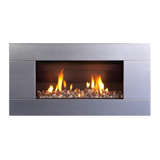
ST900 Direct Vent Gas Fireplace
Installation Manual
NEW ZEALAND EDITION
Important:
The appliance shall be installed in accordance with;
• This installation instruction booklet
• Local gas fitting regulations
• Municipal building codes
• Electrical wiring regulations
• NZS 5261, Gas installations
• Any other relevant statutory regulations.
• Must be installed by a qualified person
Manufactured by: Escea Ltd, PO Box 5277 Dunedin NZ, Ph: 03 479 0302, e:
630001_11_Manual_Installation‐Service_ST900_NZ
info@escea.net
Advertisement
Table of Contents

Related Manuals for Escea ST900


Summary of Contents for Escea ST900
- Page 1 • Municipal building codes • Electrical wiring regulations • NZS 5261, Gas installations • Any other relevant statutory regulations. • Must be installed by a qualified person Manufactured by: Escea Ltd, PO Box 5277 Dunedin NZ, Ph: 03 479 0302, e: info@escea.net...
- Page 2 • Gas pipe placement to the front left of the cavity. • The ST900 electronic control system is designed to work within the temperature range of 0°C to 60°C, with a humidity level that is non condensing. This is to ensure safe operation of the electronic and gas control system.
- Page 3 630001_11_Manual_Installation‐Service_ST900_NZ Recommended Installation Process: The following diagram illustrates the steps required to install your gas fire, and the trades required at each stage. The sequence in which you choose to do these tasks will vary depending on your individual scenario.
-
Page 4: Table Of Contents
630001_11_Manual_Installation‐Service_ST900_NZ Contents: Product Description Creating the Cavity Hearth and Floor Clearances Wall Linings Vertical Clearances Corner Installations Laying Gas Pipe Connecting Gas Pipe Power Supply 10.0 Fixing Fire to Wall 11.0 Removing the Firebox Glass 12.0 Installing the Flue system 13.0 Fitting the Flue Restrictor 14.0... -
Page 5: Product Description
The dimensioned drawing below shows the size of opening that must be created to fit the ST900. The wall directly above the fire should be finished / gibbed / lined after the fire has been installed, unless there is an access hatch or the chase is open to the ceiling cavity, which allows the flue to be installed after the wall has been lined. -
Page 6: Hearth And Floor Clearances
The drawings below are suggestions that may be used as a GUIDE for those consumers who do decide to locate their TV above an ST900 gas fire. These drawings show ways to reduce the amount of warm air rising off the fireplace and onto the TV. - Page 7 The diagram to the right shows the minimum and maximum allowable size for mantles or protruding surfaces mounted above the ST900. Note: Escea does not recommend placement of items on the mantles shown in the diagram to the right. This is because of the potential for items placed on or above the mantle to be affected by the heat rising from the appliance.
-
Page 8: Corner Installations
Soft copper should be run directly to fire and connected onto the regulator with flare nut (3/8” BSP thread). The regulator that is supplied with the fire MUST NOT BE REMOVED. Removal of the regulator, or replacing it with one not intended for use with an Escea fire, will void the limited appliance warranty. -
Page 9: Power Supply
This appliance will draw a maximum of 100mA from a 240V supply. If desired, an optional battery-pack can be purchased which will allow the ST900 to run without mains power, allowing the fire to run in the event of a power cut. This battery pack uses 3x D cell batteries. -
Page 10: Removing The Firebox Glass
630001_11_Manual_Installation‐Service_ST900_NZ 10.0 Fixing the Fire to the base and wall: It is a requirement that this fire be securely fastened to the wall and base. Once the fire has been pushed back into the correct position, use wood screws (or other suitable fasteners) to fix the fire to the cavity through each of the four holes in the corners, as shown in the diagram to the right. -
Page 11: Installing The Flue System
630001_11_Manual_Installation‐Service_ST900_NZ 12.0 Installing the Flue System: Ensure all flue components are Simpson Duravent Direct Vent Pro 5” x 8,” no other flue types may be used. Note: Consult section 12.13 to ensure correct length of flue is calculated. There are two basic types of Balanced Flue System installations: •... - Page 12 630001_11_Manual_Installation‐Service_ST900_NZ 12.5 Vertical Only Flue Diagram: Use this diagram to determine what percentage of flue restriction in required to ensure safe and correct operation of the ST900 decorative gas fireplace. ...
- Page 13 630001_11_Manual_Installation‐Service_ST900_NZ 12.6 Horizontally Terminating Flue Diagram: Use this diagram to determine what percentage of flue restriction in required to ensure safe and correct operation of the ST900 decorative gas fireplace. ...
- Page 14 630001_11_Manual_Installation‐Service_ST900_NZ 12.7 Vertically Terminating flue with a Horizontal Offset: Use this diagram to determine what percentage of flue restriction in required to ensure safe and correct operation of the ST900 decorative gas fireplace. ...
- Page 15 630001_11_Manual_Installation‐Service_ST900_NZ 12.8 Standard Flueing Configurations: The following flue components are available from escea in kitset form. DVF‐H DVF‐V...
- Page 16 630001_11_Manual_Installation‐Service_ST900_NZ 12.9 Locating the Flue Terminal: The flue terminal must be located using the information given in the following diagram and table based on NZS 5261...
- Page 17 630001_11_Manual_Installation‐Service_ST900_NZ Table 16 – Minimum clearances required for flue terminals shown in figure 3 Ref. Item Minimum Clearances (mm) Natural draught assisted Below eaves, balconies and other projections: Gas appliances up to 50 MJ/h input Gas appliances over 50 MJ/h input From the ground, above a balcony or other surface (see note 6) From a return wall or external corner (see note 6) From a gas meter (M) (see 2.5.4.9 for vent terminal location of...
- Page 18 630001_11_Manual_Installation‐Service_ST900_NZ 12.11 Sealing ‘through roof’ and ‘through wall’ penetrations: For ‘through roof’ penetrations, use a Deck-tite flashing or equivalent to create a weather- tight seal between the flue and the roof cladding. For ‘through wall’ penetrations, this will require the use of a Wall Thimble. The Wall Thimble will ensure you have suitable clearance from combustibles as well as sealing the penetration.
- Page 19 630001_11_Manual_Installation‐Service_ST900_NZ 12.13 Points to note when planning the Installation of the Escea DV flue: This flue system cannot be cut to length. Correct lengths must be selected for each installation. For a full list of available flue lengths, contact your Escea retailer.
-
Page 20: Fitting The Flue Restrictor
630001_11_Manual_Installation‐Service_ST900_NZ 13.0 Fitting the Flue Restrictor: If your flueing configuration requires that you fit a flue restrictor (see graph in section 12.5, 12.6 & 12.7 of this manual to find out if your configuration requires a flue restrictor), follow the instructions below. -
Page 21: Converting To Natural Gas
630001_11_Manual_Installation‐Service_ST900_NZ 14.0 Converting to Natural Gas: Where a conversion to natural gas is needed, the following steps should be followed 14.1 First you need to remove the burner by removing the screw holding it in place on the left hand side of the firebox (Fig. 1). Then remove the 1.3mm burner jet (Fig. - Page 22 630001_11_Manual_Installation‐Service_ST900_NZ Finally, put the sticker supplied in the conversion kit in onto the dataplate of the ST900 in the position shown. The sticker must be signed and dated by the installer who has converted the fire.
-
Page 23: Placing The Fuel Bed
630001_11_Manual_Installation‐Service_ST900_NZ 15.0 Placing the Fuel Bed Media: Your ST900 Gas fire will be supplied with a Fuel Bed kit. Follow the instructions below for the Fuel Bed kit that applies to you. 15.1 Driftwood Fuel Bed: First scatter one layer of the supplied white stones evenly across the base of the firebox, ensuring there are no stones or driftwood pieces inside the pilot flame surround guard. -
Page 24: Checking Operating Pressure
Checking Operating Pressure: WARNING: The regulator that is supplied with the fire MUST NOT BE REMOVED. Removal of the regulator, or replacing it with one not intended for use with an Escea fire, will void the limited appliance warranty. The regulator is factory set (not adjustable) to supply the correct operating pressures based on the minimum and maximum inlet pressure in the table below for the relevant gas type. -
Page 25: Covering Up The Fire
The ST900 fascia uses these four hooks for attaching to the fire. Do this by lining up the fascia hooks with the receptacles on the sides of the fire. Lift the fascia so that the hooks are above the receptacles, and let it drop down into position until it is secure and free from movement. - Page 26 18.3 Cleaning the ST900 Fascia: The fascia must be cold before starting any form of maintenance or cleaning. If your Stainless Steel fascia requires cleaning, 3M Stainless Steel cleaner is recommended. If your Powder Coated (Painted) fascia requires cleaning, you must only use a damp cloth to give it a gentle wipe.
-
Page 27: Operating Instructions
Note: If this is the first time running the ST900 the air will need to be purged from the gas lines. To do this, follow the instructions below to switch the fire on and then switch it off. - Page 28 To turn off the ST900, push the ON/OFF button (13) and the OFF display (6) will start blinking. Push the SET button (14) again to shut down the gas flow to the ST900 and switch it off. The OFF display (6) will now appear in the display.
- Page 29 630001_11_Manual_Installation‐Service_ST900_NZ 19.5 Adjusting desired temperature in Thermostat mode: When you want to change the set room temperature while In the AUTOMATIC mode and the AUTO display (9) is showing, you can push the UP button (12) or the DOWN button (15).
- Page 30 To turn on the ST900, push the ON/OFF button on the touch pad. The LED will start to blink while the pilot starts to spark. The pilot should be lit within a few seconds, during which time the LED will blink while the ignition process takes place.
-
Page 31: Sounds And Smells
Similarly, if ‘Flame Down’ is pressed while the unit is in the ‘pilot’ flame position, nothing will happen. To shut down the gas flow to the ST900, press the On/Off button and the LED will begin to blink. If while using the Remote control in the Manual mode, you push any button on the Touch Control, the unit will receive the command of the touch control and follow it. -
Page 32: Annual Service Check
630001_11_Manual_Installation‐Service_ST900_NZ 21.0 Annual Service Check: The ST900 Fireplace should be serviced annually to ensure it continues to operate in a safe manner. This annual service check should involve the following • Replace thermocouple • Check glass assembly gasket • Clean pilot and main burner jets •... -
Page 33: Warranty Terms And Conditions
630001_11_Manual_Installation‐Service_ST900_NZ WARRANTY TERMS & CONDITIONS: 24.0 Provided that the Product is installed as per ESCEA’s Installation Manual and the step by step warranty procedure has been followed as per instructions issued by ESCEA, (documented in the Agent Manual), and the product is operated and maintained in accordance with ESCEA operating and maintenance instructions, then for the first period of twelve (12) months from the date of purchase ESCEA will pay the cost of repairing or replacing any part of the Product that is deemed by ESCEA to be faulty. For the second period of twelve (12) months from the date of purchase ESCEA will supply replacement parts only, without charge. Parts and Labour for the first twelve (12) months: a) ESCEA, at its sole discretion, may modify, adjust, repair, or replace the faulty products. The warranty period on parts and labour shall be for twelve (12) months from the date of purchase. b) Labour costs will only be reimbursed when ESCEA specified procedure has been followed, and ESCEA has authorised service work before it was carried out. Parts Only for the second twelve (12) months: a) ESCEA, at its sole discretion, will provide replacement parts to the Distributor, retailer or repair service. Faulty parts MUST be returned to ESCEA. The parts only warranty period shall be for twelve (12) months and will commence twelve (12) months after the acceptance date of the Products by the ESCEA retailer. General Terms and Exclusions: 1. All repairs made within the Limited Warranty period shall be covered by this Limited Warranty for a period of three (3) months from the date of completion of the repair, or for the remainder of the overall Limited Warranty period, whichever is the longer. 2. If the buyer or any other party modifies any part of the Product within the Limited Warranty period without the prior written consent of ESCEA then the Limited Warranty shall be void. ESCEA may, at its sole discretion, decide that the Limited Warranty is void in relation to any part of the product, which has been modified. ESCEA must be notified of all claims under this Limited Warranty as soon as possible, but in any event not later than two (2) weeks of the claimant becoming aware of the circumstance giving rise to the claims. No ESCEA Distributor, retailer, employee or other third party is authorized to make any modification, extension, or addition to this Limited Warranty, whether verbal or written. ESCEA reserves the right to discontinue products or make substitutions, in such event, the buyer may receive ...
Need help?
Do you have a question about the ST900 and is the answer not in the manual?
Questions and answers