Escea DL850 Installation And Service Manual
Gas fireplaces
Hide thumbs
Also See for DL850:
- User manual (12 pages) ,
- Installation & service manual (56 pages) ,
- User instructions (14 pages)

Related Manuals for Escea DL850


Summary of Contents for Escea DL850
- Page 1 Installation / Service Guide DL850 / DL1100 Gas Fireplaces For the latest documentation, visit www.escea.com 630241_1 630203_4...
- Page 3 Failure to follow these instructions could cause a malfunction of the heater, which could result in death, serious bodily injury, and/or property damage. Failure to follow these instructions may also void your fire insurance and/or warranty. Who can install this product: Installation must be carried out by a registered installer who, on completion of the instal- lation, must issue a: AUS: Certificate of Compliance NZ: Energy Work Certificate in accordance with national and/or local codes. If these are not issued then the Escea war- ranty may be void. Warranty Repair and Annual Servicing: Warranty repair work must be carried out by a recognised Escea Gas Fire Technician. It is recommended that recognised Escea Gas Fire Technicians are also used to carry out an- nual servicing requirements (particularly during the warranty period). For contact details of authorised Escea Gas Fire Technicians in your area, please contact the retailer from whom the appliance was purchased.
-
Page 4: Table Of Contents
Contents Installation Process and Product Description Recommended Installation Process: Product Description: Product Dimensions: Creating the Cavity Cavity Shape: Flue Configuration (If less than 4m flue length): Fascia: Cavity Base: Hearth: Wall Linings: Mantle Clearance: Television Clearances: Corner Installations: B10 Distance from Fireplace base to Fascia base: Installing the Electricity and Gas to the Appliance Power Supply: Network Cable: Gas Pipe Sizing: Gas Pipe Position: Gas Isolating Valve: Pressure Test Point: Installing the flue Horizontal Powerflue Description Installing in Accordance with Relevant Codes: Creating the Hole in the Outside Wall... - Page 5 Fixing the Appliance to the Base and Wall: Fixing Appliance to Base: Fixing Appliance to Wall: Removing the Glass Converting the Appliance Gas Type Checking the Pilot Ignition E10 Log Fuel Bed Installation E11 River Stone or Coal (Pebbles) Fuel Bed Installation E12 Crystalight Fuel Bed Installation E13 Crystalight and Driftwood Fuel Bed Installation E14 Checking the Operating Pressure E15 Home Automation Setup Fitting the Fascia and Finishing Installation Fitting the Fascia Panels: Fitting the Velo Four Sided Fascia Panels Fitting the Quadrato Fascia Panels Fitting the Rado Fascia Panels Locating Wall Mount Cradle for Wireless Control: Operating the Appliance for the First Time: Normal Operating Sounds and Smells: Cleaning the glass Installation Checklist Service Manual Error Codes: Serial Number: Checking Operating Pressure: Cleaning the Log Set and Glass: Servicing the Horizontal Powerflue Wall Terminal Removing or Cleaning Fan Replacing Electronic Drawer...
-
Page 6: Installation Process And Product Description
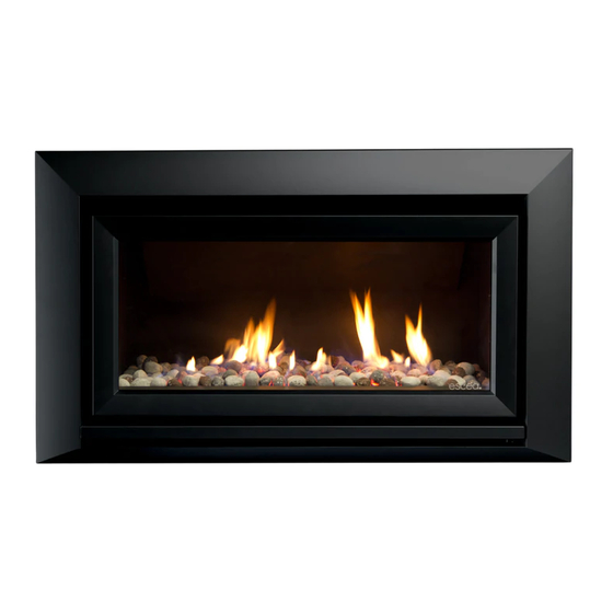
Create the Cavity Install electrical / gas Install appliance and Finish installation, connections and flue finish cavity fit fascia and test system appliance Section B Section C, D Section E Section F Product Description: The Escea DL series gas fire is a room sealed gas appliance designed to be built into a cavity. These appliances are flued using co-linear flexible aluminium flue connected to a powerflue terminal. The user will control their fire with the Radio Frequency (RF) remote that will normally be left in its wall mount cradle. In addition to the RF remote the appliance has a single auxiliary On/Off button on the unit. When not in operation it is in a standby mode unless it is physically isolated from the mains supply. -
Page 7: A3 Product Dimensions
Product Dimensions: Creating the Cavity Cavity Shape: The DL850/DL1100 is suitable for both timber framed and masonry cavities. For a masonry cavity the inside width of the cavity must be at least 960mm (DL850) or 1260mm (DL1100) to fit the appliance and must be at least 600mm deep to accommo- date the flue connections. A timber framed cavity can be shaped to suit. The cavity shape will be dependent on two things: -the flue configuration (section B2) -the fascia (section B3) - Page 8 Flue Configuration (If less than 4m flue length is required): If your flue system is less than 4m long (as shown in diagrams below), then a simple flex- ible flue is required. If you wish to install a longer flue run, up to 12m, see section B3. Horizontally Terminated: (utilises the escea horizontal power flue enclosure kit) The horizontal offset of the terminal can be any amount up to the total flue length listed below. Please consult with Escea’s technical staff if your intended flue configuration steps outside of the bounds of the flue configurations shown below. Y Maximum = 1.5m Y Minimum = 0m X Maximum = 4m X Minimum = 0m X + Y Maximum = 4m Y Maximum = 4m Y Minimum = 0m...
- Page 9 Overall flue length: 400mm Min. 4m Max. Vertically Terminated: (utilises the escea vertical power flue enclosure kit) 1.2m Co-axial flue: Vertical Powerflue Enclosure X Max = 4m Y Max = 4m X + Y Max = 4m...
-
Page 10: B2 Flue Configuration (If Less Than 4M Flue Length)
Flue Configuration (If more than 4m flue length is required): f your flue system is greater than 4m long (as shown in diagrams below), then a flexible flue with condensate trap and rigid PP tube flue lengths is required. If you wish to install a longer flue run, up to 12m, see section B3 1.2m Co-axial Flue Vertical Powerflue Ø80mm / Ø100mm PP Tube Ø100mm Condensate Trap Ø80mm / Ø100mm Flexible Flue 12m MAX ESCEAWALL TERMINAL Ø80mm / Ø100mm PP Tube Ø100mm Condensate Trap Ø80mm / Ø100mm... - Page 11 Installing a Condensation Trap (If more than 4m flue length) Internal condensate drainage pipework must be a minimum of 19mm ID (typically 22mm OD) plastic pipe and this should “fall” at least 45mm per metre away from the condensate collector, taking the shortest practicable route to the termination point. The first component of the condensate discharge system should be a ‘U’ trap or syphon with a mini- mum trap height of 75mm. The use of a syphon would be the preferred method when discharging to an external termination point. However care must be taken when installing the syphon to ensure that it is mounted to manufacturer’s instructions. In order to minimise the risk of freezing during prolonged periods of very cold weather, one of the following methods of terminating condensate drainage pipe should be adopted: 1: INTERNAL TERMINATION: Wherever possible, the condensate drainage pipe should be terminated at a suitable internal foul water discharge point such as (a) an internal soil and vent stack or (b) an internal kitchen or bathroom waste pipe, washing machine waste pipe etc. A suitable permanent connection to the foul waste pipe should be used. If connecting into the waste of a sink or basin the ‘U’ trap or syphon should be at least 100mm above the height of the sink or basin. The possibility of waste pipes freezing downstream of the connection point should be considered when determining a suitable connection point - e.g. a slightly longer pipe run to an internal soil stack may be preferable to a shorter run connecting into a kitchen waste pipe discharging directly through the wall to an external drain. Where “gravity discharge” to an internal termination is not physically possible (e.g. the discharge point is above the appliance location, or access is obstructed by a doorway), or where very long internal pipe runs would be required to reach a suitable discharge point, the following measures may be adopted - 2: USE OF A CONDENSATE PUMP (TO AN INTERNAL TERMINATION): Condensate can be removed using a proprietary condensate pump.
-
Page 12: B3 Fascia
Fascia: The cavity shape is dependent on the fascia type. There are three fascia types available with the DL850 and DL1100: Velo (4 Sided) Rado Quadrato The Velo and Quadrato fascias sit proud of the finished wall surface and have a simple cavity shape. The cavity may be constructed from combustible materials. The Rado fascia sits flush with, or inset from, the finished wall surface and has a more complex cavity shape. The cavity framing and wall facing for a minimum of 300mm directly above the Rado fascia must be constructed from non-combustible materials. Please check the style of fascia before commencing the building of the cavity to the dimensions shown below. The cavity for Velo and Quadrato fascias may be constructed from combustible timber framing materials. Note: It is not necessary to line the sides, top or back of the cavity. Cavity for Velo or Quadrato Fascia Cavity for Rado Fascia Ideal Cavity Dimensions (mm): DL850: (min) (max) (min) (max) -
Page 13: B5 Hearth
Gibbing damage or distort vinyl wall coverings. For durability of finishes and surfaces you should contact the relevant manufacturer for their specification. Wall Finish RADO For more detail on cavity construction, view the “Drawings for Architects” in the technical section of the Escea website. Mantle Clearance: Please refer to the diagram to the right. Man- tles or protruding ledges mounted above the heater that are made from combustible materials, must not extend outside of the dimensions shown. -
Page 14: B10 Television Clearances
B11 Corner Installations: If a cavity is to be created in a corner, the following draw- ing gives the minimum sized interior wall dimensions. 45º Minimum corner install dimensions (mm): DL850 DL1100 1145 1260 B12 Distance from Fireplace base to Fascia base: The following side-on views show the measurement from the base of the fireplace to the base of the Fascia. VELO QUADRATO... -
Page 15: Installing The Electricity And Gas To The Appliance
Installing the Electricity and Gas to the Appliance Power Supply: Whilst the cavity is being created consideration should be given to appropriate location of a standard 3 pin, EARTHED 230/240V power outlet. This must be within 1.0m of the rear bottom left hand corner of the appliance. IMPORTANT: Locating the power outlet within the cavity makes the installation very neat but the provision MUST be made to be able to switch the power supply off and on (electrical isolation switch) and MUST be accessible after the heater has been installed. This is normal- ly done by means of a separate switch which must be located adjacent to the appliance as per AS/NZS 5601.1.2010. -
Page 16: C3 Gas Pipe Sizing
Gas Pipe Sizing: Gas pipe should be sized as per the requirements of AS/NZS 5601. The pipe sizing must be sufficient to deliver the following volume of gas to the heater with all other gas appli- ances in the home running at the same time: DL850 Gas Consumption = 38MJ/hr DL1100 Gas Consumption = 43Mj/hr Gas Pipe Position: Regulator Inlet gas connection Gas pipe entry positions The DL850 / DL1100 has 2 possible entry points for gas pipe, on the rear right corner and the front right. Each is sealed by a ‘knock-out’ . Remove only the knock-out which you re- quire, and place the supplied rubber plug into the hole. You will need to make a small cut into the rubber plug to allow the gas pipe to pass through, keeping the plug as air-tight as possible. The gas connection on the appliance is a ½” female BSP at the very front right of the ap- pliance. This section of the piping will need to be flexible to allow for pipe disconnection and firebox removal. Gas Isolating Valve: It is recommended that a gas isolating valve be installed as close to the regulator on the gas inlet side as possible with easy access if the fascia is removed. This will allow for easier... -
Page 17: Installing The Flue
Installing the flue For Horizontally terminated flue, see section D1. For Vertically terminated flue, see section D1 Horizontal Powerflue Description Note: The appliance is designed only to operate using the approved flexible flue supplied by Escea. Other brands of flue may not fit, and this will affect the appliance warranty. The Horizontal Powerflue Wall Terminal must be installed in the correct orientation. This allows for the correct operation of the flue system and prevents the ingress of rain. The Horizontal Powerflue Wall Terminal must be weather-tight when installation is com- plete to prevent damage to the dwelling. It must be installed by a suitably qualified person. Access to the powerflue from the outside must be provided for servicing, and this should be taken into consideration when installing in tall buildings. -
Page 18: D2 Installing In Accordance With Relevant Codes
D2 Installing in Accordance with Relevant Codes: The location of the Horizontal Powerflue Wall Terminal must be installed in accordance with AS/NZS 5601 and any other relevant building codes. If possible, avoid installing the Horizontal Powerflue Wall Terminal in areas exposed to high winds and extreme weather. Some of the minimum clearances for a fan assisted wall terminal are listed below; please refer to AS/NZS 5601 Gas installation standard for full guidance on the design of the flue system. Where possible allow a greater clearance. Below eaves, balconies and other projections 200mm From the ground, above a balcony or other surface 300mm From a return wall or external corner 300mm From a gas meter or regulator vent 1000mm From electricity meter or fuse box 500mm From a drain pipe or soil pipe 75mm Horizontally from any building structure or obstruction 500mm... -
Page 19: D3 Creating The Hole In The Outside Wall
D3 Creating the Hole in the Outside Wall When cutting the hole in the outside wall, be mindful of how the installation Horizontal Powerflue Wall Terminal will be finished, the installation must be weatherproof. Ideal hole/cavity size for Horizontal Powerflue Without Side Brackets With Side Brackets 298mm 360mm 298mm 298mm 175mm Excluding allowance for flue which exits here The Horizontal Powerflue Wall Terminal can be attached to the wall in two ways, A) From the front of the terminal: B) By attaching the optional Wall Terminal Installation Brackets to the sides of the cavity and attaching the Horizontal Powerflue Wall Terminal to these, from the front: D4 Installing the Horizontal Powerflue Wall Terminal Attach the Ø100mm and Ø75mm flexible aluminium flues to the spigots on the rear of the Horizontal Powerflue Wall Terminal using the hose band clamps supplied. Plug the powerflue electrical cable into the back of the Horizontal Powerflue Wall Terminal. Ensure that the electrical cable is firmly secured to the wall terminal or building to pre- vent damage or disconnection if pulled... -
Page 20: D5 Vertical Power Flue
Fit the Horizontal Powerflue Wall Terminal into the hole and fix in place, making sure the installation is sealed appropriately to prevent the ingress of water from outside the wall cladding. NOTE: It is the responsibility of the installer to ensure the Horizontal Powerflue Wall Terminal is installed to all relevant building codes to ensure weather tightness. This may nesesitate the use of appropriate flashing material where appropriate. IMPORTANT: Ensure that flashings do not restrict the air intake slot around the periphery of the cowl D5 Vertical Power Flue The Vertically terminated flue kit is intended for use within an accesable roof space or accesable ‘chimney’ construction. Service access must be provided. Typical Installation Vertical High Wind Terminal Ø203mm / 8” Co-axial Flue ‘Decktite’ or similar flashing Roof Space Ensure Power Flue unit is securely braced using integral brackets. Hose band clamps Power cord to appliance... -
Page 21: D6 Installation The Restrictor Plate (Vertical Power Flue Only)
D7 Running the Flue Run the Ø100mm and Ø75mm flexible aluminium hoses from the cavity to the rear of where the Horizontal or Vertical Powerflue Terminal will be installed. The flue system for the DL850 / DL1100 is zero rated, so no spaces are required between the flue and any timber framing. Allow enough stretch in the flexible aluminium flue to allow it to be able to protrude through the wall/ceiling to enable it to be connected to the Powerflue Terminal. It is advisable to secure the flexi flue at regular intervals to prevent vibration and move- ment. Steel wire or ‘builders strapping’ may be used for this purpose. -
Page 22: Installing The Appliance
Note: Ensure the wall has been lined and finished (gib stopped/painted/covered) before starting the appliance install. Plug the powerflue electrical cable into the appliance in the back right hand side. With the appliance electrical cord plugged into the outlet in the cavity, carefully place the appliance on the cavity base and push it into the cavity. Bring the gas connection through the outer shell of the appliance and connect it to the regulator on the bottom right hand side of the appliance. The gas pipe should have already been tested as per section C. Regulator Inlet gas connection Gas pipe entry positions Note: The regulator that is supplied with the fire MUST NOT BE REMOVED. Removal of the regulator, or replacing it with one not intended for use with an Escea fire, will void the limited appliance warranty. Connecting the Network Cable If a network cable is being installed for a wired connection to an internet router/network (as per Section C2) then bring the cable through the chassis as described earlier and attach it to the correct socket inside the electronic tray. Remove the electronic tray by unscrewing the two screws at the... -
Page 23: E3 Connecting The Flue
Replace the lid and electronic tray by reversing the steps above. Ensure the network cable does not interfere with the pressure switch hoses beneath the firebox and does not rest against the firebox bottom surface. Connecting the Flue Remove the lid of the appliance by removing the two screws on either side of the top front of the appliance. If there is not enough room to reach into the cavity the appliance may need to be pulled forward slightly out of the cavity. Reach through into the cavity and connect both the inlet flue (Ø75mm) and the exhaust flue (Ø100mm) to their respective spigots on the rear of the appliance. Orientate and position the hose band clamps to provide easy access from the front of the appliance. Tighten the flue onto the spigots by the use of the hose clamps (provided). Ensure the flue connection is as sound as possible and that the flue connection is air tight. Fixing the Appliance to the Base and Wall: There are several ways that the appliance can be fixed against movement: It is a require- ment that this appliance be securely fastened to the wall and base. Note: It is important that the outer fascia is used during this process to ensure that the appliance is located in the appropriate position within the cavity. Fixing Appliance to Base: The Appliance has several holes along the front edge of the base panel that have been provided to allow installers to screw the appliance to the floor. Because of a lack of access for drilling it may be necessary to mark the appropriate location for these screws and then remove the appliance and drill holes into hard flooring. Alternatively a socket set can be used to drive in hex headed screws. Fixing Appliance to Wall: The installer must also fix the appliance to the sides of the cavity using the brackets on the side of the appliance shown below. These flanges can be bent to accommodate the installation. -
Page 24: E7 Removing The Glass
Note that the fibreglass tape around the glass can mark carpet and furnishings. Converting the Appliance Gas Type This appliance has been factory set to operate on Natural Gas only. To convert the appli- ance to operate on propane or ULPG, proceed as follows: □ Remove the 2 screws securing the burners in place and lift out the burners as shown. □ Remove the 2 screws securing the pilot guard shown below and lift it out. Jets DL850 Front DL850 Rear DL1100 Front DL1100 Rear Ø2.5mm Ø2.3mm Ø2.6mm Ø2.6mm Propane Ø1.4mm Ø1.3mm Ø1.4mm Ø1.3mm ULPG Ø1.2mm Ø1.1mm... -
Page 25: E9 Checking The Pilot Ignition
Turn the restrictor indicator to the vertical position as shown. □ Remove the regulator screw cap and screw out the nylon adjuster screw to remove the existing spring. □ Replace the spring with the blue spring supplied in the conversion kit and reassemble the regulator □ Adjust operating pressure to 2.3kPa for DL1100 (Propane / ULPG) and the DL850 (Propane) OR 2.6kPa for DL850 (ULPG) by turning the nylon adjustor screw whilst the appliance is running on maximum. □ Adhere the Conversion label over the top of the Natural Gas data on the appliance data plate. □ Adhere the ‘Propane’ or ‘ULPG’ label over the top of the existing Natural Gas label on the side of the appliance (if accessable). Checking the Pilot Ignition The placement of the electrode is CRITICAL to the opera- tion of the fire. The gap is factory set but in the event that... -
Page 26: E10 Log Fuel Bed Installation
E10 Log Fuel Bed Installation Note: There are several types of fuel bed for the DL850 and DL1100. Please check which fuel bed you have been supplied with and follow the installation instructions for that fuel bed carefully. Starting at the right hand side, place the ‘v’ shaped log in place, using the pins on the rear burner to line up with the holes in the base of the log. Ensure the port pattern follows the log shape: Place the other logs using the same method as above, using the diagrams below to ensure correct log placement DL850 DL1100 Pour the supplied ‘embers’ into all the visible gaps around the front of the logs, being careful to avoid letting any fall down between the pilot head, spark electrode and pilot guard. If possible keep the area where the pilot hood flame is directed at the burner ports clear. -
Page 27: E11 River Stone Or Coal (Pebbles) Fuel Bed Installation
Replace the glass and the three glass retainers. Note: Improper positioning of logs may create carbon build-up and will alter the unit’s performance. Malfunctioning due to improper log placement is not covered under war- ranty. E11 River Stone or Coal (Pebbles) Fuel Bed Installation Note: There are several types of fuel bed for the DL850 and DL1100. Please check which fuel bed you have been supplied with and follow the installation instructions for that fuel bed carefully. Place all the River Stones or Coals in a single layer atop the burners, covering the entire area. Be careful to avoid letting any fall down between the pilot head, spark electrode and pilot guard, and if possible keep the area where the pilot hood flame is directed at the burner ports clear to aid reliable ignition. Replace the glass and the three glass retainers. Note: Improper positioning of Stones/Coals/Pebbles may create carbon build-up and will alter the unit’s performance. Malfunctioning due to improper Stone/Coal/Pebble place- ment is not covered under warranty. E12 Crystalight Fuel Bed Installation Note: There are several types of fuel bed for the DL850 and DL1100. Please check which fuel bed you have been supplied with and follow the installation instructions for that fuel bed carefully. Place all the Crystalight pieces in a SINGLE LAYER atop the burners, covering the entire area. Be careful to avoid letting any fall down between the pilot head, spark electrode and pilot guard, and if possible keep the area where the pilot hood flame is directed at the burner ports clear. Replace the glass and the three glass retainers. Note: Improper positioning of Crystalight may create carbon build-up and will alter the unit’s performance. Malfunctioning due to improper Crystalight placement is not covered under warranty... -
Page 28: E13 Crystalight And Driftwood Fuel Bed Installation
E13 Crystalight and Driftwood Fuel Bed Installation As per E12, and then once Crystalight has been evenly spread across the base of the firebox place the supplied driftwood on top of the Crystalight as shown: DL850 DL1100 E14 Checking the Operating Pressure WARNING: The regulator that is supplied with the fire MUST NOT BE REMOVED. Removal of the regulator, or replacing it with one not intended for use with an Escea fire, will void the limited appliance warranty. Check the operating pressure at the regulator located at the front RH corner of the appli- ance. This is best done before the fascia panels have been fitted to avoid fascia damage. A pressure test point is available for the operating test pressure (as shown below). A = Operating Pressure test point Maxitrol B = Pressure adjustment screw (To access first remove metal cap) C = Inlet gas connection ( ½” Female BSPT) □ Check the inlet pressure to the appliance. Attach manometer tube to the first test point upstream of the appliance (typically at the gas utility meter or auto change device for a propane bottle station) -
Page 29: E15 Home Automation Setup
5.0kPa 5.0kPa 5.0kPa Operating pressure 2.30kPa 1.0kPa 2.30kPa E15 Home Automation Setup Escea D-Series fireplaces have a simple interface for connection to a home automation system. Simply put this allows the fireplace to be woken up and started and then shut down. The “Close to wake” connection shown is essentially taking one of the 3.3 volt DC pins on the fireplace micro controller and pulling it down to ground. In order to isolate the fireplace from the automaton system a relay needs to be used as shown. This allows you to use any nominal voltage to drive the relay while keeping the fireplaces 3.3V supply isolated. Required relay Connector Fireplace on fireplace Terminal block +3.3VDC µ From Automation system Connector and terminal block supplied by Escea Note: you will need to match the relay coil voltage with the voltage from your automaton system. - Page 30 The Home Automation connection can be found inside the DL850 and DL1100 electronic tray (for access instructions see section E2). The socket is shown to the right and can be identified by green wires. Home Automation Operation: Relay closed The fireplace will start in a medium setting until it receives a signal from the remote con- trol unit (up to 4 minutes). Once the remote has communicated with the fireplace it will turn on and begin operating the fireplace thermostatically. The remote will use whatever temperature the user has previously set and cannot be altered by the home automation system. The fireplace will continue to operate while the relay is closed. Note: If the fireplace cannot communicate with the remote controller within 10 minutes of the relay contact closure then the fireplace will shut down and return to standby. The remote controller is required to be operating within range of the fireplace for its safe operation. Relay open If the fireplace was operating with a closed relay then upon opening the relay contacts the fireplace will shut down and return the remote controller to its standby mode when it next updates (up to 4 minutes). While the relay is open the fireplace will be in standby mode and available for manual operation by the user. END OF SECTION E By the end of this section, you should have: □ The appliance installed in the cavity □ The appliance fixed to the cavity base and wall lining □ The appliance plugged into a mains electricity supply □ The selected fuel bed installed and glass in place □ The appliance gas supply attached and pressure tested with all other gas appli- ances running □...
-
Page 31: Fitting The Fascia And Finishing Installation
Fitting the Fascia and Finishing Installation Fitting the Fascia Panels: To avoid scratches or knocks to the fascia panels of this heater they must be fitted at the complete conclusion of the installation process. It may be necessary to use the outer fascia to initially locate the heater but then remove it again so that there is no chance of damage. Use the soft gloves provided whenever handling the fascia. Never, ever rub the fascia panels. Refer to cleaning instructions supplied with fascia. There are thee fascia types available with the DL850 / DL1100: Velo (4 Sided) Rado Quadrato The fascia installation will depend on the fascia and cavity type. For: Velo Four Sided, see section F2 Quadrato, see section F3 Rado, see section F4... -
Page 32: F2 Fitting The Velo Four Sided Fascia Panels
Fitting the Velo Four Sided Fascia Panels Step 1: Ensure the glass and all glass retain- ers are securely fitted. Note: If the glass gasket requires a replacement, call your nearest Escea agent who will ensure the part is replaced with the correct type. In the event that the glass is broken by impact, purchase the replacement from an authorised Escea agent only. Step 2: Attach the Velo Outer Fascia Bracket to the top lid as shown below: Step 3: Fit the Velo Outer Fascia brackets to the bottom left and right sides of the appliance as shown. STEP 8 STEP 8... - Page 33 Step 4: Wearing the fabric gloves supplied with your fascia kit, hang the Outer Fascia from the Velo Outer Fascia Bracket attached to the top lid as shown Step 5: Check that the Outer Fascia is centred on the chassis. Screw the Outer Fascia to the chassis at the bottom left and right of the Outer Fascia as shown Step 6: Attach the two inner fascia brackets as shown: Step 7: Hang the Inner Fascia from the metal bracket on the front of the firebox. Centre the Inner Fascia relative to the Outer Fascia. Step 8: Screw the Inner Fascia to the bottom left and right of the firebox as shown...
-
Page 34: F3 Fitting The Quadrato Fascia Panels
Step 9: Push the supplied magnet brackets into position. Place the bottom fascia trim onto the magnets. If this panel does not fit, adjust the outer fascia side to side or the ap- pliance in/out until the trim fits well. Fitting the Quadrato Fascia Panels Step 1: Ensure the glass and all glass retainers are securely fitted Note: If the glass gasket requires a replacement, call your nearest Escea agent who will ensure the part is replaced with the correct type. In the event that the glass is broken by impact, purchase the replacement from an authorised Escea agent only. Step 2: Attach the Quadrato Outer Fascia Bracket to the top lid as shown below Step 3: Screw the two Quadrato Outer Fascia studs into the two brackets at the bottom left and right of the appliance as shown below. Step 4: Attach the two inner fascia brackets as shown: Step 5: Hang the Inner Fascia from the metal bracket on the front of the firebox. - Page 35 Step 6: Screw the Inner Fascia to the bottom left and right of the firebox as shown below. Step 7: The Outer Fascia is now fitted over the top of the Inner Fascia. Hang the Outer Fascia (larger one) from the 30 degree flange at the top of the fireplace, being very care- ful not to damage either the Inner or Outer Fascias as there is not a lot of room to fit the Outer over the Inner. Once the Fascia is hung on this flange and clear of the Inner Fascia it will swing down and press firmly into place. TAKE CARE: When securing the outer fascia, ensure it does not hit the inner fascia. Step 8: Once it has clipped onto the fireplace check that the Fascia is parallel with the wall. The fascia installation is now complete.
-
Page 36: F4 Fitting The Rado Fascia Panels
Fitting the Rado Fascia Panels Step 1: Ensure the glass and all glass retainers are securely fitted. Note: If the glass gasket requires a replacement, call your nearest Escea agent who will ensure the part is replaced with the correct type. In the event that the glass is broken by impact, purchase the replacement from an authorised Escea agent only. Step 2: Attach the Rado Outer Fascia Bracket to the top lid as shown below. Note: Ensure the cor- rect orientation of the bracket. If the bracket is installed upside down, the fascia will not fit. Step 3: Fit the Rado Outer Fascia brackets to the bottom left and right sides of the appliance as shown below. STEP 8 STEP 8... - Page 37 Step 4: Attach the lower foot to the fascia by screwing it in the positions shown below. STEP 4 STEP 5 + 6 STEP 7 + 8 STEP 9 Step 5: Hang the Outer Fascia from the magnet bracket attached to the top of the fire- box. Insert the fascia so that it is parallel with the front of the gas fireplace. The Hex-nuts attaching the magnets to the fascia will locate in the holes on the magnet bracket, secur- ing the Outer Fascia in the correct position. If this fascia does not fit, check to make sure the magnet bracket installed above is in the correct orientation. Step 6: Fit the two screws at the base of each side of this fascia. The heater may have to be adjusted in or out of the cavity to ensure fascia fits correctly.
- Page 38 Step 7: Attach the inner fascia brackets to the Inner Fascia as per the instruction page sup- plied with the fascia. Hang the top edge of the Inner Fascia from the lip that extends at 45 degrees from the top of the firebox. This fascia is attached to the fire at its base by two screws. Leave the screws loose enough to be able to adjust the Inner Fascia. Step 8: Check that the Inner Fascia is centred. If this panel is not centred, adjust the Inner Fascia side to side un- til the spaces on either side are even. Tighten the screws to fix the Inner Fascia in place. Step 9: Push the supplied magnet brackets into position. Place the bottom fascia trim onto the magnets. If this panel does not fit, adjust the outer fascia side to side or the ap- pliance in/out until the trim fits well.
-
Page 39: F5 Locating Wall Mount Cradle For Wireless Control
The appliance’s remote contains the thermostat that will sense the room temperature and communicate this back to the heater via radio frequency. A wall mount cradle has been provided for the wireless control and where possible the control should be housed in this cradle. The location of this cradle should be decided by taking into account the following factors; Simple, convenient access for the user Away from air flow and drafts through the room The parts of the room that people are likely to spend time Away from direct sun light A suitable distance away from the heater. Ideally 1.2m to 1.5m from the floor The radio frequency signal will go through some walls but for best results Escea suggest that the cradle position is between 1 and 5 metres away from the heater. Please ensure that cradle is screwed firmly onto the wall using the screws provided. Operating the Appliance for the First Time: Remove the battery cover on the rear of the remote. Insert the new “AA” size batteries, paying attention to the polarity. You should now see on the display of the remote the time showing “0:00”. To turn the fire on, press the “POWER” button once, and within a few seconds the appli- ance will begin its startup sequence. NOTE: The appliance begins its startup with a thirty second pre-start purge, where the combustion fan runs on its own to clear the firebox before it tries to ignite. During the pre-purge the remote will alternately show the remote’s “Set” temperature and a rotating segment indicator to show that the fire is in start up mode and will try to ignite. -
Page 40: F7 Normal Operating Sounds And Smells
Normal Operating Sounds and Smells: Note: Each time the fire is lit from cold the glass may fog up with condensation. This is normal and the condensation will disappear within a few minutes once the glass heats Sounds It is possible that you will hear some sounds from your gas appliance. This is perfectly normal due to the fact that there are various types of materials used within your appli- ance. Listed below are some examples. These are all normal operating sounds and should not be considered as defects in your appliance. • Fan: Escea gas appliances use electric fans to push heated air further into the room. It is not unusual for the fan to make a “whirring” sound when ON. This sound will increase or decrease in volume depending on the speed setting of your fan. • Gas Control Valve: As the gas control valves turn ON and OFF, a dull clicking sound may be audible, this is the normal operation of a valve. When the fire is switched off after being run for a while, there may be popping and fluttering noises as the residual gas in the burners burns away. These are normal and should be no cause for concern. • Unit Body/Firebox: Different types and thicknesses of steel will expand and contract at different rates resulting in some “cracking” and “ticking” sounds being heard throughout the heat- ing and cool down processes. Smells: The first few times the unit is operated, the unit may release an odour and the flames will appear orange caused by the curing of the paint, the burning off of the starch in the gas logs and the oils in the metal. This is a temporary curing process which will disappear with use. Cleaning the glass A deposit on the inside of the glass, caused by the starch in the logs, may appear as a build up after several uses. If this film is not removed, it will bake on and may become... -
Page 41: Installation Checklist
Installation Checklist Go through the following checklist to ensure you have installed the appliance correctly □ Correctly sized cavity to suit your fascia and flue configuration □ Correct clearances to combustibles and mantles around the fascia □ An electrical isolating switch to the appliance, accessible after finished installation □ Correctly sized gas supply with a pressure test point, ensuring adequate supply with all other gas appliances in the dwelling running □ A weather-tight installed Horizontal or Vertical Powerflue Terminal with clearance as specified by AS/NZ5601 □ Reasonable access to the outside face of the Horizontal Powerflue Wall Terminal for maintenance purposes OR □ Access to the Vertical Power Flue Enclosure for maintenance purpose □ Flue attached to the rear/bottom of the Powerflue Terminal leading back to the appli- ance □ The electrical cable from the Powerflue Terminal attached to the rear of the installa- tion and run back to the appliance cavity in an electrically safe manner □ The appliance fixed to the cavity base and wall lining □ The appliance plugged into a mains electricity supply □ All gas joints and pressure points leak tested, and soapy water and drop tests com- pleted on gas pipework □ Gas type conversion process carried out if required □ Log, coal, river stone or crystalight fuel bed correctly installed □ Glass correctly fitted □ A completely fitted fascia □... -
Page 42: S Service Manual
Service Manual IMPORTANT: • This appliance must be serviced every 12 months. • Any service operation should be carried out only by a suitably qualified and trained person. • Gas and electricity supply MUST be isolated before any service operation is carried out on this appliance. • This manual should be left with the appliance. • DO NOT MODIFY THIS APPLIANCE. Error Codes: This gas fire has been designed to show error codes to help explain and identify any fault situation that occurs. These codes will appear on the wireless remote control in the form of a large letter “E” with a number beside it. Codes can normally be reset by turning the heater off then on again at the mains power wall switch. -
Page 43: S2 Serial Number
The bimetallic snap disk mounted on the spigot seal plate at the rear of the fire has tripped. The possible causes for this could include: • Possibly fascia panels installed incorrectly resulting in restricted air flow at the top of the fire. Appliance Over • Room air fans may be slowed or stalled. Remove firebox, check that Temperature fans are plugged in, cleaned, and free turning Sensor Trip • The gas regulator being set too high resulting in excess heat build- • The inlet flue not being connected and the appliance drawing warm air from the cavity. Check flues are securely connected at both ends. The valve solenoids have failed the pre-ignition test. This is to detect a faulty valve solenoid. However, it is possible a wire has dislodged. • Check that the connections to each solenoid are secure and in place. It may be that the connections on the ends of the wires need to be Valve Solenoid tightened a little (e.g. with a pair of pliers) to ensure a robust con- Check Failure nection to the valve terminal. • Disconnect and reconnect the firebox connectors ensuring they are firmly pushed into place. • It could also be that one of the solenoids on the valve inside the fire has failed. If this is the case the valve will need to be replaced. The remote cannot communicate with the fire. Reasons for this could include: •... -
Page 44: S3 Checking Operating Pressure
NEVER RUB THE FASCIA. The outside of the fascia’s must only be cleaned with a clean damp cloth, dry off after cleaning. The high temp silver powder coating that is used on Escea fascia parts contains certain amounts of aluminium that when rubbed too hard will oxidise leaving a black smudge that cannot be removed. - Page 45 directly outwards. Note: Be careful of any flash- ing that may have been installed above the terminal. Removing this plate gives complete access to the fan for servicing or replacement. Check that all the seals are still intact. Check the fan electrical terminals, motor and impellor are not corroded. Ensure there is no signs of leakage in or around the terminal. When reassembling the terminal, line up the round silicon grommets with the outlet tube of the fan and push the cowl back into place. Ensure all seals are still in place and replace all of the screws to hold the cowl in the correct position. Servicing a vertical Powerflue: If the vertical Powerflue needs servicing the fan can be accessed without disturbing the final twin walled flue length or roof terminal. To gain access to the fan and electrical terminals remove the eight screws that hold the base of the Powerflue to the lid, making sure to support the base while removing the screws. Note: When inspecting or working on the Powerflue take care not to damage the two flexible flue pipes that connect to the Powerflue base. Once the base has been removed clean away any dust or debris found and check that the fan electrical terminals, motor and impellor are not corroded. Also check for signs of leak- age in or around the Powerflue.
-
Page 46: S6 Removing Or Cleaning Fan
Removing or Cleaning Fan As part of regular service procedure, it is recommended that the fan is removed for clean- ing. Dust will build up on the fan rotor and in the cavity where the fan is located. This can be removed by the service person using a hearth brush and a vacuum cleaner. ISOLATE THE POWER AND GAS SUPPLY TO THE FIRE BEFORE COMMENCING THIS PROCEEDURE Step 1: Remove the inner/outer fascia, front glass, and log set as described in section S4. Step 2: Remove the guard covering the electrical connections and earth lead by removing the 3 screws. Step 2: Disconnect the gas supply from the fire and unplug the three wiring looms connecting the valve and spark electrode on the bottom right of the fire box. Unscrew the earth strap Step 3: Remove the 2 screws holding the pressure switch bracket. Carefully pull the switch out and remove the hoses from the rear of it. Step 5: Remove outer shell top by removing the screws in each corner and sliding out. 630203_1... - Page 47 Step 6: Reach in and loosen the clamps holding the flexible inlet and outlet tubes and detach them from the fire. Step 7: Remove firebox from heater by taking out the screws from the bottom corners, lifting the firebox over the chassis lip and pulling firebox directly outwards (as shown). Note: Proceed with caution as the firebox assembly is heavy. Be aware of the components on the underside of the firebox that could easily be damage. Step 8: Take out the 4 screws on top of fan plate assembly. Step 9: Unplug wires lift the fan unit up and out to fully remove fan assembly. Step 10: Clean fans, removing all dust build up. Step 11: Replace fan assembly and firebox by repeating these steps in reverse order. NOTE: □ Ensure the earth strap is reconnected (Screwed) into the electrical guard (step 2) □ Ensure the Pressure Switch hoses are connected to the correct nozzles without any kinks or restrictions. These can be identified by an “H” (high) and “L” (low) labelled on the hoses and the pressure switch. (step 3)
-
Page 48: S7 Replacing Electronic Drawer
If an ethernet / network cable is con- nected the lid of the drawer will have to be removed and the cable unplugged before the drawer is completely extracted from the fire. Reverse this procedure to refit. Ensure drawer is fully seated into the draw housing. Replacing a Wireless Control: If the wireless control becomes lost or damaged, a new one can be ordered from any Escea retail agent. When you have the new remote, the following procedure needs to be followed to “teach” the remote FLAME to only communicate with that fire. EFFECT ON LY BOOST 1. Ensure the fire and remote are set to “Off” (only the time is dis- played on the remote). 2. Press the – (minus), + (plus) and the Fan Boost buttons simultane- SET TIME ously until all the characters on the display light up. This will put the... -
Page 49: S9 Annual Service Procedure
3. Press and hold the – (minus) button until the two large temperature digits reading 00 start to flash slowly. Release the – (minus) button. The remote control is now ready to be addressed to the fire. 4. Press and hold the red auxiliary on/off button (found on the front face of the fireplaces electronic drawer, shown on the left with an arrow) for a minimum of eight seconds, or until the two large temperature digits start counting upwards from 00 to 99 repeatedly on the remote control. Note: Pressing the red auxiliary button on/off button will start the fire. Once the remote control is counting the fire can be turned off by pressing the red auxiliary button again. 5. Press the large power button in the middle of the remote control to exit the test mode and return to normal operation. The remote should only be displaying the time. Check the fire will start using the remote control by pressing the large power button. Turn it off again using the remote control. 6. The fire is now re-addressed to the remote control. Annual service procedure: □ Isolate power and gas supply to fire. □ Remove front glass and clean inside of glass. □ Remove fuel bed and brush off any soot. □ Clean electrode and pilot hood of any carbon build up and ensure correct gaps between electrode and pilot hood □ Remove burners and blow compressed air through the burner ports. □ Remove jets and clean injector hole with solvent. □ Remove firebox to give access to fan, brush and vacuum any dust build up from fan blades. □ Vacuum any dust from the cavity that houses the fan and from the underside of the fire box around the valve and solenoids. -
Page 50: S10 Wiring Diagram
S10 Wiring Diagram: 630203_1... -
Page 51: S11 Warranty
S11 Warranty 1 This document sets out the express warranties that apply in respect of Escea products purchased in either: (a) Australia with the exception of Western Australia, provided by Glen Dimplex Australia Pty Limited ABN 69 118 275 460 of Unit 2, 205 Abbotts Road, Dandenong, Victoria 3175 (Phone number 1300 556 816) (we, us our). (b) Western Australia, provided by Airgroup Australia of 28 Division Street, Welshpool, Perth, WA 6106 (Phone number 893 502 200) (we, us our). (c) New Zealand, provided by Escea The express warranties in this document apply to the particular Escea product which this warranty has been included in the packaging for or otherwise supplied with (the Escea product). 2 Escea express warranty Subject to the exclusions in section 3, we warrant under this express warranty that the below parts of the Escea product will be free from defects of materials or workmanship for the periods specified below (with each of the below periods commencing on the date the Escea product was purchased by you as a brand new product from a retailer located in the regions outlined in section 1): Part Type of express warranty Firebox and Heat Exchanger 10 years parts and labour warranty* All other parts 1 year parts and labour warranty followed im- mediately by 1 year parts only warranty* * Where a Escea product is covered by a parts and labour warranty, the warranty covers both the repair of the defective part or the provision of a spare part to replace the defec- tive part and the installation of that part. - Page 52 (b) the Escea product requires repairs due to damage resulting from accident, misuse, incorrect installation, cleaning or maintenance, unauthorised modification, tampering or unauthorised repairs by any persons, use of defective or incompatible accessories or exposure to abnormally corrosive conditions; (c) the defective part relates to a consumable part of the Escea product which require routine replacement; (d) you are unable to provide us with reasonable proof of purchase for the Escea product; (e) the breakdown occurs after the expiry of the express warranty period set out in sec- tion 2; or (f ) the Escea product was not purchased in any of the regions outlined in section 1 as a brand new product. Escea is not responsible for any staining or smoke damage caused by flue products discharged through the flue cowl. 4 Consumer Guarantees Our goods come with guarantees that cannot be excluded under the Australian Consum- er Law. You are entitled to a replacement or refund for a major failure and for compensa- tion for any other reasonably foreseeable loss or damage. You are also entitled to have the goods repaired or replaced if the goods fail to be of acceptable quality and the failure does not amount to a major failure. 5 How to make a claim You may make a claim under this warranty by contacting us by: For New Zealand, contact the dealer you purchased the fire from to file a claim.
- Page 53 6 Warranty claims If you make a valid claim under a parts and labour warranty and none of the exclusions set out in section 3 apply, we will, at our election, either: (a) repair the relevant part of the Escea product; or (b) replace the relevant part of the Escea product with a product of identical specification (or where the product is superseded or no longer in stock, with a product of as close a specification as possible). We will also arrange for the relevant repaired or replacement part to be installed at no charge to you. If you make a valid claim under a parts only warranty and none of the exclusions set out in section 3 apply, we will, at our election, repair or replace the relevant part. You ac- knowledge that installation is not covered under a parts only warranty, however, we may, for a fee, install the repaired or replacement part for you. We will, on request, provide you with a quote for the installation of the repaired or replacement part. Goods presented for repair may be replaced by refurbished goods of the same type rather than being repaired. Refurbished parts may be used to repair the goods. Escea products are designed and supplied for normal domestic use. We will not be liable to you under this warranty for business loss or damage of any kind whatsoever. 7 Costs of warranty claim in Australia (excluding Western Australia) Where you make a claim under this warranty, an authorised repairer may need to attend your premises to inspect the Escea product. We may charge you a service call fee if a repairer will be required to travel more than 30 kilometers from the nearest Glen Dimplex service centre to your location. You may obtain details on the location of our service cen- tres and our service call fees by visiting our website (www.glendimplex.com.au) or calling our customer care line (1300 556 816).
- Page 54 630203_1...
Need help?
Do you have a question about the DL850 and is the answer not in the manual?
Questions and answers