Sign In
Upload
Download
Table of Contents
Contents
Add to my manuals
Delete from my manuals
Share
URL of this page:
HTML Link:
Bookmark this page
Add
Manual will be automatically added to "My Manuals"
Print this page
×
Bookmark added
×
Added to my manuals
Manuals
Brands
PEUGEOT Manuals
Engine
satelis 125 cc
Workshop manual
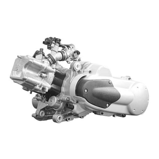
PEUGEOT 125 CC Workshop Manual
4-stroke engine
Hide thumbs
Also See for 125 CC
:
Owner's manual
(18 pages)
1
2
Table Of Contents
3
4
5
6
7
8
9
10
11
12
13
14
15
16
17
18
19
20
21
22
23
24
25
26
27
28
29
30
31
32
33
34
35
36
37
38
39
40
41
42
43
44
45
46
47
48
page
of
48
Go
/
48
Contents
Table of Contents
Bookmarks
Table of Contents
Table of Contents
Characteristics
Capacities
Special Important Points
Oil and Fuel
Tightening Torque
Special Tools
Disassembly
Putting the Engine on the Stand
Removal of the Primary Transmission Cover
Removal of the Drive Pulley
Removal of the Driven Pulley
Removal of the Rocker Cover
Removal of the Chain Tensioner
Removal of the RH Cover / Ignition Coil and Sensor
Removal of the Rotor
Removal of the Cylinder Head
Removal of the Temperature Sensor
Removal of the Thermostat
Removal of the Camshaft And/Or Rockers
Removal of the Valves or Valve Stem Seals
Removal of the Cylinder
Removal of the Piston
Removal of the Oil Pump
Removal of the RH Crankcase Half
Removal of the Oil Discharge Valve
Removal of the Water Pump
Removal of the Crankshaft
Checking the Crankshaft and Conrod Assembly
Removal of the Secondary Transmission Cover
Removal of the Secondary Transmission
Refitting Specific Components
Installing the Crankshaft LH Bearing
Installing the Water Pump Inside the RH Crankcase
Assembly of the Engine Casings
Installing the Piston Rings on the Piston
Fitting the Piston
Fitting the Cylinder
Fitting the Cylinder Head
Setting the Timing
Installing the Valve Clearance
Checking the Valve Clearance
Refitting the Rocker Cover
Miscellaneous Operations
Removal of the Oil Filter
Removal of the Water Inlet Pipe
Fitting the Drive Pulley Assembly
Changing the Drive Pulley Bearings
Removal of the Clutch Lining Assembly
Refitting the Clutch Lining Assembly
Advertisement
Quick Links
1
Table of Contents
2
Oil and Fuel
3
Removal of the Oil Filter
Download this manual
See also:
Owner's Manual
WORKSHOP MANUAL
TECHNICAL NETWORK LEADERSHIP
WORKSHOP MANUAL
-
125 CC/150 CC 4-STROKE ENGINE
Table of
Contents
Previous
Page
Next
Page
1
2
3
4
5
Advertisement
Table of Contents
Need help?
Do you have a question about the 125 CC and is the answer not in the manual?
Ask a question
Questions and answers
Related Manuals for PEUGEOT 125 CC
Scooter PEUGEOT Satelis Owner's Manual
(18 pages)
Engine PEUGEOT 150 CC Workshop Manual
4-stroke engine (48 pages)
Engine PEUGEOT 50 CC Workshop Manual
4-stroke engine 2 valves air cooling (44 pages)
Engine PEUGEOT XP6 50 Manual
(35 pages)
Engine PEUGEOT XS1P37QMA-2 Workshop Manual
50cc engine 4 stroke 2 valves sym (48 pages)
Engine PEUGEOT XS1P52QMI-3B Workshop Manual
Addition for the sym evo 2 valve 4 stroke 125/151 cc engine (20 pages)
Engine PEUGEOT MOTOR ENGINE Workshop Manual
(40 pages)
Engine PEUGEOT XS1P52QMI-4 Workshop Manual
125/151 cc 4-stroke engine 2 valves sym (48 pages)
Engine PEUGEOT TSDI Workshop Manual
50 cc injection engine (43 pages)
This manual is also suitable for:
150 cc
Table of Contents
Save PDF
Print
Rename the bookmark
Delete bookmark?
Delete from my manuals?
Login
Sign In
OR
Sign in with Facebook
Sign in with Google
Upload manual
Upload from disk
Upload from URL


Need help?
Do you have a question about the 125 CC and is the answer not in the manual?
Questions and answers