Table of Contents
Advertisement
Quick Links
Advertisement
Table of Contents

Subscribe to Our Youtube Channel
Related Manuals for FireBird Bio-Tec


Summary of Contents for FireBird Bio-Tec
- Page 1 Bio-Tec Wood Gasification Boiler...
-
Page 2: Table Of Contents
6.3 Plumbing connections 6.4 Assembly of tank insulation 6.5 Laddomat Pump Charging System 6.6 Flue Installation 6.7 Wiring instructions Commissioning Maintenance Spare Parts Tables Firebird 200mm twin wall flue system Resistance Chart – NTC25/5k Resistance Chart – Pt2000 Page 2... -
Page 3: Introduction
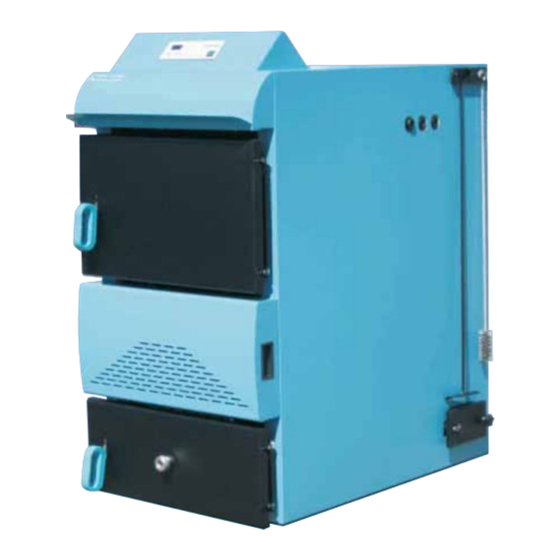
1. INTRODUCTION We would like to thank you for purchasing your high efficiency Firebird Bio-Tec wood gasification boiler. The Bio- Tec wood gasification boiler represents the very latest in high efficiency wood burning. It has a rated thermal output of 35kW and is produced in compliance with the EN 303-5 and 304 standards. -
Page 4: Health And Safety
2. HEALTH AND SAFETY When installing, commissioning or servicing a Firebird Bio-Tec boiler you must comply with all relevant health and safety regulations and recommendations. Proper safety and protective clothing should be worn, including hats, boots gloves and appropriate eye protection. -
Page 5: Technical Specification
3. TECHNICAL SPECIFICATIONS Specification Bio-Tec 35 Unit Nominal thermal output Total weight Boiler water content Litre Max. operating pressure Max. operating temperature ºC Boiler connections Inlet and outlet 1 ½ “ Inch Filling and draining ½ “ Inch Flue gas temperature (avg.) ºC... - Page 6 Hard woods such as Ash, Oak and Beech enable a longer burn time, raising the temperature quicker. Firebird sells a wood moisture meter which measures the woods moisture content. To use simply insert the two probes into the wood, along the grain a wait a few seconds for a reading.
-
Page 7: Operating Instructions
5. OPERATING INSTRUCTIONS This appliance is not intended for use by children, or persons with reduced physical, sensory or mental capabilities, or lack of experience and knowledge. 5.1 Householder User Guide: Important! Before starting the fire make sure the lower chamber door is closed. A. - Page 8 B. Filling or re-filling Once glowing embers have formed, the chamber can be filled with larger logs. Close the door after filling. You should check the upper chamber from time to time and refill if necessary. The fuel warning light will also indicate when the more wood is required.
-
Page 9: Controller Functions
5.2 Controller Functions The following is a brief explanation of the main controller buttons and icons labelled above: 1. The “ON/OFF” switch is used to switch on mains electric power switch. 2. The LED display shows boiler temperatures and other system information explained in section 5.3 3. -
Page 10: Advanced Controller Information
11. PUMP No. 1 LED – this indicates that the boiler pump (normally the Laddomat) is running. This pump is used to charge the accumulation tank. 12. PUMP No. 2 LED – indicates that the central heating pump is operating 13. - Page 11 Temperature at which the boiler cooling will be activated Parameter Factory Description set-up Boiler temperature at which boiler pump (Laddomat) will be activated Maximum flue gases temperature permitted Flue gases temperature level at which the burning process stops when glow function is not activated Flue gases temperature level at which the burning process stops when glow function is activated Boiler warming up period (minutes).
-
Page 12: Installation
Sample schematic for an open vented heating system: The following diagram represents one method of connecting the Bio-Tec boiler to the accumulation tank and heating circuit in an open vented heating system. This boiler/tank connection is often called a serial connection. In this set-up the accumulation tank charging circuit (boiler to tank via boiler pump/Laddomat) is ‘decoupled’... -
Page 13: Locating The Boiler
The recommended sizing of the accumulation tank is a minimum of 50 litres of water storage per 1kW of rated boiler output, i.e. a 35kW boiler will require a minimum tank size of 1750 litres. The Bio-Tec boiler should only be operated when connected to an appropriately sized accumulation tank. -
Page 14: Flue Installation
½ “ 6.4 Flue Installation A properly sized and insulated twin wall flue is critical to the safe and efficient operation of the Bio-Tec boiler. Table 1 shows the components of the flue system provided by Firebird. Key considerations with the installation of the Bio-Tec flue are;... - Page 15 Bring the two sides of the insulation together as so that they almost meet. Step 4. Firebird recommends that you tie three belts around the insulation jacket as shown. Tie one around the upper half, one around the middle area and the other around the lower area.
- Page 16 6.6 Laddomat 21 Firebird recommends that a Laddomat 21 pump charging system is fitted with every Bio-Tec installation. The Laddomat 21 is installed as shown in the schematic in section 6.2 The key benefits of the Laddomat 21 are; •...
- Page 17 (if connected) Sensor & Stat Connections - Right hand terminal block The table below identifies the different sensors used on the Bio-Tec boiler and the sensor type. Two types of resistant sensors are used – PT1000 and a NTC 5k/25 sensor.
- Page 18 5 terminal connections inside it labelled 1 to 5. These are connected to terminals 11 to 15 respectively on the right terminal block of the Bio-Tec. Terminals 11 to 13 relate to the temperature control; terminals 14 and 15 are for the fuel warning LED.
-
Page 19: Maintenance
7. MAINTENANCE Weekly / Every 20 hours of operation (can be carried out by the householder) • Clean the upper and lower combusting chambers using the cleaning poker provided. • Scrape the ash from the refractory stone using the semi-circular shaped poker. •... - Page 20 iii. Clean the flue gas turbulators at the back of the boiler. To do this remove the rear upper cover of the boiler and unscrew the cover of the upper opening by removing the screws as shown. Pull out the spiral turbulators (spring from spiral bar 5) out of the flue gas tube.
-
Page 21: Spare Parts
9. SPARE PARTS LIST: BIO-TEC 35kW Firebird Part No. Description CM12730 Handle for cleaning system CM12680 Fan flange CM12679 Fan flange gasket CM12677 Combustion chamber refractory stone – upper left CM12676 Combustion chamber refractory stone – upper right CM12675 Combustion chamber refractory stone – upper back CM12674 Combustion chamber refractory stone –... - Page 22 TABLES Page 22...
- Page 23 Table 1 - Firebird 200mm Insulated twin wall flue system The exploded drawing below shows the components supplied with the Firebird 200 insulated twin-wall flue system. Additional lengths and elbows can be ordered separately. Page 23...
- Page 24 Table 2 - Resistance Chart - NTC 5k/25ºC sensor (used for sensors O1, O3, O4, O5) Temperature Resistance (ºC) 48535 36465 27665 21158 16325 12694 9950 7854 6245 5000 4028 3266 2663 2184 1801 1493 1244 1041 Page 24...
- Page 25 Table 3 - Resistance Chart - PT1000C sensor (used for sensors O2 – flue gas temp) Temperature Resistance Temperature Resistance (ºC) (ºC) 1732 1751 1770 1789 1809 1828 1000 1847 1019 1866 1039 1886 1058 1905 1077 1924 1096 1943 1116 1963 1135...
- Page 26 © 2009 Republic of Ireland Northern Ireland United Kingdom Firebird Firebird Products Firebird UK Udaras Industrial Estate Shean East Central Ho. Central Ave. Baile Mhic Ire Forkhill Lee Mill Industrial Estate County Cork Newry Ivybridge, BT35 9SY Devon, PL21 9PE...
Need help?
Do you have a question about the Bio-Tec and is the answer not in the manual?
Questions and answers