
Related Manuals for FireBird Enviromax Popular C12


Summary of Contents for FireBird Enviromax Popular C12
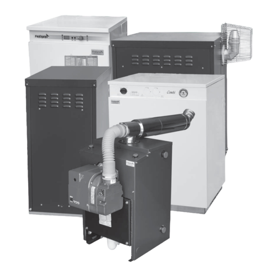
- Page 1 HEATING SOLUTIONS ENVIROMAX CONDENSING BOILERS T EC H NIC AL MAN U AL This manual must remain with the householder once installation is complete Working towards a greener planet...
-
Page 3: Table Of Contents
CONTENTS FOREWORD We would like to thank you for purchasing a high efficiency Firebird condensing oil boiler. This instruction manual is produced for the reference and guidance of qualified installation engineers, preferably OFTEC (Oil Firing Technical Association) registered. EU legislation governs the manufacture, operation and efficiency of all domestic central heating oil boilers. -
Page 4: Standards & Regulations
STANDARDS & REGULATIONS To ensure the highest standards of installation & safety, In addition, the work must comply with relevant it is important that the boiler be installed in compliance building regulations for oil fired boilers and oil with the following regulations where applicable. It is storage tanks. -
Page 5: Safety
SAFETY HEALTH & SAFETY INFORMATION THIS PRODUCT HAS BEEN DESIGNED TO THE FOLLOWING STANDARDS: The installer should be aware of his/her responsibilities under the current, local Health and Safety at Work Act. The This equipment complies with the Low Voltage Directive interests of safety are best served if the boiler is installed 2006/95/EC &... -
Page 6: First Aid
SAFETY FUEL SPILLAGE FIRST AID 1. Switch off all electrical and other ignition sources. If fuel is accidentally swallowed: * Seek medical attention immediately. 2. Remove all contaminated clothing to safeguard Do NOT induce vomiting. against fire risk and skin damage. Wash affected skin If fuel is splashed into eyes: thoroughly with soap and water and remove clothing * Wash out with running water for at least ten... -
Page 7: Householder Instructions
3.1 OPERATING PROCEDURE - HOUSEHOLDER INSTRUCTIONS POPULAR, KITCHEN, SYSTEM, HEATPAC, Thermostat Control SLIMLINE HEATPAC, SYSTEMPAC & SLIMLINE SYSTEMPAC Re-set button Temperature Set at Max 80˚C Set at Mid 70˚C Set at Min 60˚C control Mode LCD display Led power light Error lamp Burner Lockout (Please note that the following applies to the... - Page 8 3.2 KITCHEN DIGITAL CONTROLLER - HOUSEHOLDER INSTRUCTIONS...
- Page 9 OFF THE MAINS SUPPLY TO THE BOILER MAX. MIN. MID. DHW ON. on indicator light. CH. on indicator light. Burner lock out indicator light. Min. = 60˚C. High limit thermostat indicator light. Max. = 80˚C. Knock out for Firebird timer kit.
-
Page 10: Combi Timer
3.4 COMBI TIMER - HOUSEHOLDER INSTRUCTIONS Programming Switching Times Optional Twin Timer Kit Set all tappets between the “on” and “off” times required, to the outer edge of the dial (see figure 1). For example, to set the timer to come on at 8:00 a.m. and to Central heating timer Domestic hot water timer turn off at 1:00 p.m., push tappets on the dial to... - Page 11 Combipac or Heatpac. Grasslin Single Channel 24 Hour Timer The F1 Timer is used to time the central circuit only in the Firebird Slimline Combi Boiler. This means that the combi is switched on 24 hours a day when the domestic hot water is on stand by mode. The timer is simple to use and install.
-
Page 12: Regulations & Guidelines
Firebird accepts no responsibility for failure of plastic passes through the wall, should be surrounded by piping and fittings for whatever reason. -
Page 13: Positioning The Boiler
Sound levels must also be a consideration. Whilst Firebird Enviromax boilers are one of the quietest boilers on the market, some householders are particularly sensitive and the following points should be considered: 1. -
Page 14: Condensate Disposal
4.3 - CONDENSATE DISPOSAL - REGULATIONS & GUIDELINES Firebird condensing boilers, when in condensing mode, extract more heat from the flue products and the resulting condensate which is mildly acidic, needs to be drained from the boiler via a condensate pipe to the drainage system. - Page 15 4.3 - CONDENSATE DISPOSAL - REGULATIONS & GUIDELINES Boiler Boiler Condensate Drain Condensate Drain Sealed Trap Condensate Drain Trap Gully Free Draining Soil Lime Stone Chippings Soak Away Boiler Washing Boiler Machine Stack Discharge pipe Condensate drain Condensate Drain Waste Pipe Trap Condensate drain must have...
-
Page 16: Flue Regulations
450mm from painted eaves. Prevailing winds should be taken into account when siting a flue. FIREBIRD RECOMMENDS AS PER OFTEC RECOMMENDATIONS, THAT THE FLUE SHOULD BE A MINIMUM DISTANCE OF 1 METRE FROM OPENINGS SO THAT IT DOES NOT CAUSE A NUISANCE AND PERMITS THE DISPERSAL OF COMBUSTION PRODUCTS (SEE PAGE 18). - Page 17 4.4 - FLUE REGULATIONS - REGULATIONS & GUIDELINES Clearances advised by BS 5410 Part 1: 2014 Regular Appliance (Open, Low Level Discharge and Balanced) Flue Termination Clearance The basic requirement with regard to flue positioning is that no hazard or nuisance is caused by the flue gases. Diagrams 20a and 20b show clearances advised by BS 5410 Part 1: 2014.
- Page 18 BALANCED FLUE BOILERS The Firebird boiler may be set for room-sealed flue operation using a Firebird condensing balanced flue kit. This kit does not draw combustion air from inside the room. It is drawn from outside, direct to the burner by an air pipe supplied with the boiler.
- Page 19 4.4 - FLUE REGULATIONS - REGULATIONS & GUIDELINES Ventilation and Combustion Air Conventional Flue Boilers An adequate supply of combustion and ventilation air is essential for efficient and safe boiler operation and the openings for this should be positioned to cause least possible draught, with no possibility of being accidentally blocked.
-
Page 20: Flue Systems
IMPORTANT It should be noted that the normal statutory clearances The Firebird condensing boiler must not be installed required around low level flue terminals may not be with existing flue systems. A flue system suitable for wet sufficient to cope with plume dispersal from a condensing flues must be used. -
Page 21: Flue Size
4.5 - FLUE SYSTEMS - REGULATIONS & GUIDELINES INSTALLATION INSTRUCTIONS SUPPLIED WITH ALL FLUE KITS HEATPAC FLUE For right hand flue option, remove the 45˚ terminal should be tilted up two screws securing the flue, rotate the flue to prevent condensate droping and swap the removable side panels from end of flue CONDENSING BOILER CHIMNEY INSTALLATION... - Page 22 4.5 - FLUE SYSTEMS - REGULATIONS & GUIDELINES FIREBIRD ENVIROMAX FLUE SYSTEMS High level vertical & horizontal flue kits = max. flue length 6m Low level flue kits = max. flue length 3m Overall length must take into account bends where 45°...
-
Page 23: Oil Supply & Magnetic Filtration
4.6 - OIL SUPPLY & MAGNETIC FILTRATION - REGULATIONS & GUIDELINES OIL STORAGE TANK SITING FLEXIBLE OIL PIPE(S) Consult OFTEC Manuals A flexible burner oil hose is supplied with the boiler which must be wholly contained with in the appliance It is unlikely that a fire will start at an oil tank. - Page 24 4.6 - OIL SUPPLY & MAGNETIC FILTRATION - REGULATIONS & GUIDELINES TWO PIPE SYSTEMS IMPORTANT: Fire Valves should comply with OFTEC Standards OFS E101. Where installation is such that the bottom of the tank is Fitting of fire valves should comply located below the oil burner pump, a two pipe system is with BS 5410 Part 1: 2014 and required.
-
Page 25: Domestic Heating & Hot Water
The pipe should be as short as possible and may need a The Firebird Combi boilers with built in expansion tundish fitted in a protected position within the vessels have an initial air charge pressure of 1 bar. If building. - Page 26 4.7 - DOMESTIC HEATING & HOT WATER - REGULATIONS & GUIDELINES EXAMPLE: using the table on this page: When the heating system is up to full working temperature, if the pointer on the pressure gauge If total water content of system is - 150 litres should enter the red zone (between 2.5 - 4 bar and initial system pressure required is...
- Page 27 Manual Filling The flow rate of water from individual taps may be The Firebird Combi boiler comes with this system built affected by any of the following: into the appliance. It consists of a flexible hose connection with a butterfly shut off valve at each end Number of taps in use at one time.
- Page 28 Special attention should be given to existing pressure vessel air charge is correct, then fill the system heating systems where a Firebird Combi boiler has with water via the filling system used.Turn off the water replaced an existing unit. Extra effort should be...
-
Page 29: Popular
5.1 - POPULAR - TECHNICAL DETAILS & DIMENSIONS Front View Side View Top View Model Output Weight kg Dimensions(mm) Burner depth Enviromax (incl. burner) Popular C12-18 12-18 Popular C20 15-20 Popular C26 20-26 Popular C35 26-35 Popular C44 35-44 Popular C58 44-58 Popular C73 58-73... -
Page 30: Kitchen
5.2 - KITCHEN - TECHNICAL DETAILS & DIMENSIONS Front View Side View Top View Model Output Weight Dimensions(mm) Enviromax Kitchen C12/18 12-18 Kitchen C20 15-20 Kitchen C26 20-26 Kitchen C35 26-35 Kitchen C44 35-44 1046 Kitchen C58 44-58 1046 Kitchen C73 58-73 1196 851 1024... - Page 31 5.2 - KITCHEN - TECHNICAL DETAILS & DIMENSIONS Boiler Model C12/18 C20 + 26 C44 + 58 Commercial Utility Heat Output 12-18 15-20/20-26 26-35 35-44/44-58 58-73 80-100 Max. BTU/h (‘000) 40-60 50 - 90 90-120 120-200 200-250 270-340 CONNECTIONS Heating Flow 1”...
-
Page 32: Heatpac & Systempac
5.3 - OUTDOOR MODELS - TECHNICAL DETAILS & DIMENSIONS HEATPAC, SYSTEMPAC & COMBIPAC HEATPAC & SYSTEMPAC COMBIPAC C44/58 - 630 C73 - 690 C44/58 - 540 C73 - 600 C12-18 - 440 C26/35 - 520 C12-18 - 500 C26/35 - 600 Dimensions Model Output... - Page 33 5.3 - OUTDOOR MODELS - TECHNICAL DETAILS & DIMENSIONS Combipac Systempac/Slimline Systempac Heatpac / Slimline Heatpac Boiler Model C20+C26 C20+C26 C12/18 C20+C26 C44+C58 Heat Output 15-20/20-26 26-35 15-20/20-26 26-35 35-44 12-18 15-20/20-26 26-35 35-44/44-58 58-73 Max. BTU/h (‘000) 50-90 90-120 50-90 90-120 120-150...
-
Page 34: Combi
5.4 - COMBI & SLIMLINE COMBI - TECHNICAL DETAILS & DIMENSIONS COMBI Front View Side View Rear View Top View 1. Mains feed 2. D.H.W. Model Output Weight Dimensions (mm) 3. 3 bar safety Enviromax valve Combi C20 15-20 845 665 605 750 220 147 335 4. - Page 35 5.4 - COMBI & SLIMLINE COMBI - TECHNICAL DETAILS & DIMENSIONS Boiler Model C20 + C26 Heat Output kW 15-20/20-26 26-35 Max. BTU/h (‘000) 50-90 90-120 CONNECTIONS Heating Flow 22 mm 28 mm Heating Return 22 mm 28 mm Mains Cold Feed (Copper) 15 mm 15 mm Hot Water Delivery (Copper)
-
Page 36: System
5.5 - SYSTEM - TECHNICAL DETAILS & DIMENSIONS System C20, C26 & C35 System C44 Front View Side View Top View Front View Side View Top View Model Output Weight Dimensions(mm) Enviromax System C20 15-20 System C26 20-26 System C35 26-35 System C44 35-44... -
Page 37: Popular
6.1 - POPULAR - PARTS Connector Screw cap Float Cone Frame Condensate trap No. Description C12-18 C100 1 Boiler Shell 312808 312026 312026 312026 311634 311634 311481 312422 2 Heat Deflector 212810 210904 210904 210904 211643 211643 211500 212420 3 Tube Baffle 1 Way 110908 (7 off... -
Page 38: Kitchen
6.2 - KITCHEN - PARTS... - Page 39 6.2 - KITCHEN - PARTS No. Description C12-18 C20/26 C100 1 Boiler Shell 312808 312026 312026 311634 311634 311481 312422 2 Heat Deflector 212810 210904 210904 211643 211643 211500 212420 3 Tube Baffle 1 Way 110908 (7 off ) 110908 (5 off ) 110908 (5 off ) 111502 (8 off ) 111502 (8 off ) 111502 (11 off ) 111502 (10 off ) 4 Tube Baffle 4 Way 110907 (2 off...
-
Page 40: Heatpac & Systempac
6.3 - HEATPAC & SYSTEMPAC - PARTS... - Page 41 6.3 - HEATPAC & SYSTEMPAC - PARTS...
- Page 42 6.4 - COMBIPAC - PARTS...
- Page 43 6.4 - COMBIPAC - PARTS Description Boiler Shell 312135 312135 312135 Tank 310628 310628 310628 Tank Insulation 111431 111431 111431 Heat Deflector 210904 210904 210904 Tube Baffle 1 Way 110908 (5 off ) 110908 (5 off ) 110908 (5 off ) Tube Baffle 4 Way 110907 (4 off...
- Page 44 6.5 - SLIMLINE HEATPAC & SLIMLINE SYSTEMPAC - PARTS...
- Page 45 6.5 - SLIMLINE HEATPAC & SLIMLINE SYSTEMPAC - PARTS Description Slimline Heatpac C20, C26, C35 Slimline Systempac C20, C26, C35 Boiler Shell 312134 312733 Heat Deflector 210904 210904 Tube Baffle 1 Way 110908 (5 off ) 110908 (5 off ) Tube Baffle 4 Way 110907 (4 off...
- Page 46 6.6 - COMBI - PARTS Pipe work 1 Pipe work 2...
- Page 47 6.6 - COMBI - PARTS Description Boiler Shell 312135 312135 312135 Tank 310628 310628 310628 Tank Insulation 111431 111431 111431 Heat Deflector 210904 210904 210904 Tube Baffle 1 Way 110908 (5 off ) 110908 (5 off ) 110908 (5 off ) Tube Baffle 4 Way 110907 (4 off...
- Page 48 6.7 - SLIMLINE COMBI - PARTS Pipe work 1 Pipe work 2...
- Page 49 6.7 - SLIMLINE COMBI - PARTS Description Boiler Shell 312283 312283 312283 Tank 312284 312284 312284 Tank Insulation 112288 112288 112288 Heat Deflector 210904 210904 210904 Tube Baffle 1 Way 110908 (5 off ) 110908 (5 off ) 110908 (5 off ) Tube Baffle 4 Way 110907 (4 off...
- Page 50 6.8 - SYSTEM - PARTS...
- Page 51 6.8 - SYSTEM - PARTS Description Boiler Shell 312133 312133 312133 311783 Heat Deflector 210904 210904 210904 211643 Tube Baffle 1 Way 110908 (5 off ) 110908 (5 off ) 110908 (5 off ) 111502 (8 off ) Tube Baffle 4 Way 110907 (4 off...
- Page 52 7.1 - POPULAR - WIRING ELECTRICAL SUPPLY The boiler and controls require 230V 1 phase 50Hz mains electric supply protected with a 5amp fuse. This appliance must be earthed. A qualified electrician must carry out all electric wiring in accordance with current I.E.E Regulations and any local regulations which may apply.
- Page 53 7.2 - KITCHEN - WIRING ELECTRICAL SUPPLY The boiler and controls require 230V 1 phase 50Hz mains electric supply protected with a 5amp fuse. This appliance must be earthed. A qualified electrician must carry out all electric wiring in accordance with current I.E.E Regulations and any local regulations which may apply.
- Page 54 7.2 - KITCHEN - WIRING S3 T2 S3 T2 Use heat resistant cable. Protect supply with 5amp fuse.
- Page 55 7.3 - HEATPAC & SYSTEMPAC - WIRING ELECTRICAL SUPPLY The boiler and controls require 230V 1 phase 50Hz mains electric supply protected with a 5amp fuse. This appliance must be earthed. A qualified electrician must carry out all electric wiring in accordance with current I.E.E Regulations and any local regulations which may apply.
-
Page 56: Combi, Slimline Combi & Combipac
7.4 - COMBI, SLIMLINE COMBI & COMBIPAC - WIRING N T1 L2 S3 B4... - Page 57 7.4 - COMBI, SLIMLINE COMBI & COMBIPAC - WIRING N T1 T2 S3 B4 Limit Lock out Green CH Green DHW...
-
Page 58: 7.5 - Combi & Slimline Combi - Pcb Panel
Combi PCB Panel DHW On - On indicator light CH - On indicator light Burner lock out indicator light Knock out for Firebird twin timer kit Min = 60˚C High limit thermostat indicator light Max = 80˚C. System pressure gauge MAX. - Page 59 7.6 - SYSTEM - WIRING ELECTRICAL SUPPLY The boiler and controls require 230V 1 phase 50Hz mains electric supply protected with a 5amp fuse. This appliance must be earthed. A qualified electrician must carry out all electric wiring in accordance with current I.E.E Regulations and any local regulations which may apply.
- Page 60 The burner nozzle, pump pressure and air setting may have to be changed from the factory setting to suit sight conditions. KEROSENE SETTINGS FOR FIREBIRD BOILER RANGE USING RDB 2.2 & 4.2 BURNERS Variations in nozzle throughput, flue type & draught, oil viscosity etc. may give results differing from the below laboratory performance figures.
- Page 61 BURNER DEFLECTOR PLATE RESTRICTOR DISC LD2X BLAST TUBE LD2X short blast tube Deflector Restrictor disc plate Part no. 3008768 Part no. 3002447 AIR BOX 1 LD2X RDB T3 RDB T5 Hole to aid Hole to aid Hole to aid photocell photocell photocell light detection...
-
Page 62: System
N The installation certificate and the commissioning CHECKLIST FOR INSTALLING AND certificate within the boiler passport should be completed and posted to Firebird within 28 days of COMMISSIONING A FIREBIRD BOILER installation (this can also be done online on the Firebird website). - Page 63 N Set the air to what is required for the nozzle size +. 5 on and any other instructions. • OFTEC forms CD10 and CD11. the dial - example: the factory setting for a Firebird C26 • The boiler passport. has a Danfoss .65 80° ES nozzle with a pump pressure of 9 bar and air at 2.5.
-
Page 64: Servicing
Replace flexible oil lines every 2 years. and to clean heat exchanger. Combustion Check Cleaning a Firebird condensing boiler: 1. Carry out a combustion analysis. 2. Follow the steps as set out in the burner set-up 1. Remove all baffles, including the tubular baffles in section. -
Page 65: Terms & Conditions Of Warranty
N Correct commissioning will ensure that your boiler is unqualified persons. set to operate at its maximum fuel efficiency. 8. Firebird will not accept any liability in respect of any defect occurring to the product due to limescale N Consumable components, the nozzles and the oil hose build-up and or low return water temperature. - Page 66 NOTES NOTES...
- Page 68 © Copyright applies to all FIREBIRD products. Our policy is one of continual development and we therefore reserve the right to change without prior notice the specification of our products at any time and be without obligation to make similar changes in products previously produced.
Need help?
Do you have a question about the Enviromax Popular C12 and is the answer not in the manual?
Questions and answers