Table of Contents
Advertisement
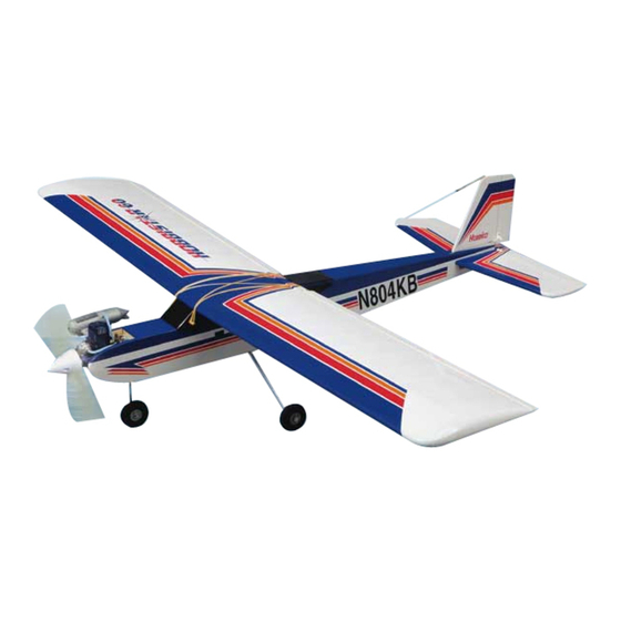
Specifications:
Wingspan: 71 in [1805mm]
Wing Area: 888 sq in [57 dm
Weight: 7 - 8 lb [3180 - 3630g]
Wing Loading: 18 - 21 oz/sq ft [55 - 64 g/dm
Length: 55 in [1400mm]
Radio: 4-channel with 4 servos
Engine: .60 to .65 cu in [10.0 – 10.6cc] two-stroke
Hobbico guarantees this kit to be free from defects in both material and workmanship at the date of purchase. This warranty does not cover any
component parts damaged by use or modification. In no case shall Hobbico's liability exceed the original cost of the purchased kit. Further, Great
Planes reserves the right to change or modify this warranty without notice.
In that Hobbico has no control over the final assembly or material used for final assembly, no liability shall be assumed nor accepted for any damage
resulting from the use by the user of the final user-assembled product. By the act of using the user-assembled product, the user accepts all resulting liability.
If the buyer is not prepared to accept the liability associated with the use of this product, the buyer is advised to return this kit immediately in new
and unused condition to the place of purchase.
READ THROUGH THIS MANUAL BEFORE
STARTING CONSTRUCTION. IT CONTAINS
IMPORTANT INSTRUCTIONS AND WARNINGS
CONCERNING THE ASSEMBLY AND USE OF
THIS MODEL.
© Copyright 2003
ASSEMBLY INSTRUCTIONS
]
2
2
]
WARRANTY
TM
See more of our products at www.hobbico.com
1610 Interstate Drive
Champaign, IL 61822
(217) 398-8970, Ext. 2
airsupport@hobbico.com
HCAZ3064 for HCAA2125 V1.1
Advertisement
Table of Contents

Related Manuals for Hobbico Hobbistar 60 MK III


Summary of Contents for Hobbico Hobbistar 60 MK III
-
Page 1: Assembly Instructions
Planes reserves the right to change or modify this warranty without notice. In that Hobbico has no control over the final assembly or material used for final assembly, no liability shall be assumed nor accepted for any damage resulting from the use by the user of the final user-assembled product. By the act of using the user-assembled product, the user accepts all resulting liability. -
Page 2: Table Of Contents
Introduction INTRODUCTION..........2 Congratulations and thank you for purchasing the SAFETY PRECAUTIONS........3 Hobbico Hobbistar .60 MKIII. You've made the right ADDITIONAL ITEMS REQUIRED......3 decision by purchasing a “real” model airplane that Radio system ............3 uses a .60-size engine and a 4-channel radio. Once Engine ..............3... -
Page 3: Safety Precautions
Protect Your Model, Yourself & Others Items Required Follow these Important Safety Precautions These are the items not supplied with the Hobbistar .60 MKIII that must be purchased separately. Where 1. Your Hobbistar .60 MKIII should not be appropriate, order numbers are provided in parentheses. considered a toy, but rather a sophisticated, working model that functions very much like a full-size RADIO SYSTEM... -
Page 4: Tools, Building Supplies, Accessories
purchase a more powerful ball bearing engine Pliers with wire cutter (HCAR0630) anyway, you’ll have to remember to throttle back to Masking tape (TOPR8018) slow the model while learning to fly. A suitable K & S #801 Kevlar thread (for stab alignment, propeller and spare propellers will also be required K+SR4575) (most two-stroke .60 engines run well with a 12 x 6... -
Page 5: Kit Inspection
Kit Contents list on this page. Product Support: Telephone: (217) 398-8970 Fax: (217) 398-7721 E-mail: airsupport@hobbico.com Parts Photographed 1. Fuselage 8. 1/4" x 1/2" x 10" [6 x 12 x 255mm] 12. -
Page 6: Ordering Replacement Parts
Ordering Replacement Parts To order replacement parts for the Hobbico Hobbistar .60 MKIII ARF, use the order numbers in the Replacement Parts List that follows. Replacement parts are available only as listed. Not all parts are available separately (an aileron cannot be purchased separately, but is only available with the wing kit). -
Page 7: Tighten The Covering
apply epoxy to all mating surfaces. (In other words, Tighten the Covering apply epoxy to both sides of the joiner in the middle and to the inside of both the joiner on the top and the joiner on the bottom.) Hold the joiners together with clamps. -
Page 8: Assemble The Wing
4. Seal the edges of the covering around the 2. Test fit the aileron to the wing with four CA engine compartment with a thin coat of 30-minute hinges but do not glue them in yet. If it is difficult to epoxy. -
Page 9: Join The Wing
drawn into the hinge gap thus gluing the aileron to the wing. Note the CA applicator tip (HCAR3780) on the CA bottle to control and pinpoint the CA that comes out. 7. Stack a few paper towels over each other and cut them into approximately 2"... -
Page 10: Assemble The Fuselage
Make certain the joiner is installed upright (so the Assemble the Fuselage wing tips are higher than the middle of the wing). Make adjustments where necessary for a good fit (sanding the top and bottom of the joiner to even the MOUNT THE STABILIZER AND FIN edges or remove excess epoxy may be required). - Page 11 4. Turn the fuse upside-down. Stick a T-pin 6. Use a fine-point felt-tip pen such as a Top Flite ® through the bottom of the firewall centered side-to- Panel Line Pen (TOPQ2510) to mark the outline of side. Tie a small loop in one end of a 50" [1300mm] the fuselage on the top and bottom of the stab.
- Page 12 12. Use 30-minute epoxy to glue the fin to the fuse. Hold the fin in position with masking tape. Before the epoxy hardens, use a Hobbico Builder's Triangle ® (HCAR0480) to see if the fin is perpendicular to the stab.
-
Page 13: Mount The Landing Gear
MOUNT THE LANDING GEAR 5. Mount the nose wheel to the nose gear wire with a 4mm wheel collar and a 3 x 5mm screw on both sides of the wheel. The same as the main wheels, be certain to file a flat spot on the wire for the outer wheel collar and add a drop of oil to both sides of the wheel to help it spin freely. -
Page 14: Mount The Engine
connector into the hole, then slip on a washer. Add a small drop of threadlocker to the threads, then screw on a thumb nut. Tighten the nut, but not so much as to stop the connecter from rotating in the hole. -
Page 15: Install The Fuel Tank
4. Test fit the muffler to the engine. If necessary, 4. Fit the fuel line to the short aluminum tube. Cut use a Dremel tool with a drum sander or a hobby the fuel line to the correct length so that when the knife to trim the fuselage to accommodate the fuel line weight (“clunk”) is installed, it will be near, muffler. -
Page 16: Hook Up The Controls
7. Connect the other pushrod to the servo arm and the torque rod the same way. 8. Center the servo arm. Adjust the length of the pushrods by turning the clevises in or out until both ailerons are centered. Refer to this photo while mounting the aileron servo. HOOK UP THE CONTROLS 2. - Page 17 7. Mount the elevator control horn to the elevator with two 2 x 20mm Phillips-head screws. 8. Carefully enlarge the holes in the elevator and rudder servo arms with a hobby knife and a #11 blade or a 5/64" [2mm] drill. 5.
- Page 18 one-end wire pushrod to hook up the throttle. A the square hole in the left side of the fuselage for the nylon clevis is used on the aft end of the pushrod to on/off switch. Drill two 3/32" [2.4mm] holes for the connect it to the servo arm and a threaded pushrod switch mounting screws and mount the switch.
-
Page 19: Mount The Muffler, Prop And Spinner
MOUNT THE MUFFLER, PROP AND FUEL LINES + 1/8 Turn 1/2 Turn 4. Install the prop washer and prop nut. Tighten Refer to this photo while mounting the muffler the prop nut “finger-tight,” then use the correct-size and installing the fuel lines. wrench (12mm for most engines) to tighten the prop nut by turning it 1/2 turn, plus another 1/8 turn. -
Page 20: Prepare The Model For Flying
Prepare the Model for Flying This is where the model should balance for the first flights. Later, you may wish to experiment by shifting the C.G. up to 1/2" [13mm] forward or 1/2" [13mm] BALANCE THE MODEL (C.G.) back to change the flying characteristics. Moving the C.G. -
Page 21: Center The Servos
If however, the tail drops, the model is tail heavy and the inside of one of the fuselage sides in front of the the model will require weight on the nose to balance. firewall. Due to the likelihood of fuel coming into Determine how much weight will be required by contact with the double-sided foam tape that holds the temporarily placing varying amounts of Great Planes... -
Page 22: Check The Control Directions
CHECK THE CONTROL DIRECTIONS Note that pulling the elevator stick back moves the elevator up (which, in flight, pushes the tail down, thus raising the nose of the plane to climb). The best way to keep this in mind is to think in Pull Stick Back (Down) terms of a pilot in an actual airplane. -
Page 23: Adjust The Throttle
carburetor is not fully closed, adjust the pushrod at the connector on the carburetor arm or at the clevis on the servo arm until the carburetor is closed. Trim Lever Up Throttle Stick Down 4. Install a silicone retainer on all the clevises (elevator, rudder, ailerons, throttle). -
Page 24: Identify Your Model
Start with the elevator… More Throw More Throw More Throw Moving the pushrod inward on the control horn results in more throw. To get more control surface movement, move the pushrod farther in on the control horn. Moving the pushrod farther out yields less control surface throw. 1. -
Page 25: Checklist
If you do not yet have a propeller balancer, ask your Spare parts: flight instructor or another club member if they will Suitable propellers help you balance your propellers. We use a Top Flite Glow plug Precision Magnetic Prop Balancer (TOPQ5700) in #64 rubber bands (stored in container with talcum ™... -
Page 26: Range Check
3. Turn on the transmitter and receiver. One at a Engine Safety Precautions time, operate each control on the airplane using the transmitter. Make certain each control is responding correctly. This must be done before every flight. Failure to follow these safety precautions may There are several types of malfunctions that can be result in severe injury to yourself and others. -
Page 27: Ama Safety Code
AMA Safety Code (excerpt) Flying Read and abide by the following Academy of Model These flying instructions are not an endorsement for Aeronautics Official Safety Code: learning to fly on your own, but are printed so you can know what to expect and what to concentrate on GENERAL while learning under the tutelage of your instructor. -
Page 28: Taxiing
TAXIING LANDING Remember, it is assumed that your instructor is When ready to land, pull back the throttle stick fully operating the model for you. while flying downwind just before making the 180- degree turn toward the runway. Allow the nose of the Before the model is ready for takeoff, it must first be set model to pitch downward to gradually bleed off up to roll straight down the runway.
Need help?
Do you have a question about the Hobbistar 60 MK III and is the answer not in the manual?
Questions and answers