Table of Contents
Advertisement
Quick Links
Fully licensed through the
Red Bull GmbH - Austria
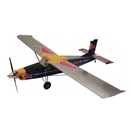
Technical data :Pilatus PC6-L
Wingspan
Length
Take off weight
Wing Area
Wing load
Motor set
Please read the instruction manual carefully and take notice of the safety guidelines.
If the model is given to a third party, always include this instruction manual to the model.
INSTRUCTION MANUAL
FLWA4100 - PILATUS PC6-L
2200 mm
1740 mm
5500 g
86,6 dm²
63,5 g/dm²
FW 5065/330
The Flitework Gmbh assumes no liability in case of misprints. Technical amendments reserved.
Distributed by
www.hobbico.de
Advertisement
Table of Contents

Related Manuals for Hobbico FLWA4100


Summary of Contents for Hobbico FLWA4100
-
Page 1: Instruction Manual
INSTRUCTION MANUAL FLWA4100 - PILATUS PC6-L Fully licensed through the Red Bull GmbH - Austria Technical data :Pilatus PC6-L Wingspan 2200 mm Length 1740 mm Take off weight 5500 g Wing Area 86,6 dm² Wing load 63,5 g/dm² Motor set FW 5065/330 Please read the instruction manual carefully and take notice of the safety guidelines. -
Page 2: Table Of Contents
TABLE OF CONTENTS General informations ............2 Wing assembly ..............12 Environment protection infos ........2 Installation of the landing flaps ........12 Introduction ................2 ESC and battery position..........13 Safety precautions ...............3 Get the model ready to fly ..........13 Recommended accessories ..........4 Check the Control Directions ........13 Recommended drive set ..........4 Balance the Model (C.G.) ..........14 RC Equipments ..............4... -
Page 3: Safety Precautions
SAFETY PRECAUTIONS 7. If you are not already an experienced R/C pilot, you should fly the model only with the help of a competent, experienced 1. Your Pilatus PC6-L should not be considered a toy, but rather R/C pilot. a sophisticated, working model that functions very much like a full-size airplane. -
Page 4: Recommended Accessories
RECOMMENDED ACCESSORIES ADHESIVES AND BUILDING SUPPLIES This is a partial list of items required to finish the Pilatus PC6-L In addition to common household tools and hobby tools, this that may require planning or decision-making before starting is the “short list” of the most important items required to build to build. -
Page 5: Spare Parts For The Pilatus Pc6-L
Tel: 01805 110111 (nur für Deutschland) Tel: 01805 110111 (nur für Deutschland) (Anrufkosten: (Anrufkosten: 14 Cent/Min. a. d. dt. Festnetz; 14 Cent/Min. a. d. dt. Festnetz; Mobilfunk max. 42 Cent/Min.) Mobilfunk max. 42 Cent/Min.) Email: Hobbico-Service@Revell.de Email: Hobbico-Service@Revell.de Order n° Part name FLWA4101... -
Page 6: Content Of Delivery
CONTENT OF DELIVERY PART LIST • 1x Fuselage with magnetic holded canopy • 1x Right wing with fl aps • 1x Cowling with exhaust pipes • 1x Carbon fi bre wing joiner 800 x 16 mm • 1x Rudder complete with carbon fi ber joiner •... -
Page 7: Assembling The Main Gear
ASSEMBLING THE MAIN GEAR ❏ 3. Fix the suspension strut with shims and M4 internal ❏ 1. Degrease the plastic bushings and glue it into the thread bolts together with the threaded rod. If the landing aluminium bearing blocks, using 5 min. epoxy glue. gear is fi xed, lock on both sides with M4 lock nuts. -
Page 8: Installing The 5065 Engine
INSTALLING THE 5065 ENGINE ❏ 3. Screw the 38mm bolts with M4x20 screws to the fi rewall, ❏ 1. Cut out the template from page 14 and fi x it with tape using 20x4mm shims on both sides of the fi rewall frame. on the fi rewall frame of the Pilatus. -
Page 9: Elevator Assembly
ELEVATOR ASSEMBLY ❏ 1. Insert the elevator servos so, that the servo cables are pointing in fl ight direction. If the servos meet together in the middle of the fuselage, take distance plates to get them free. If you are using a S-BUS system like Futaba, dont forget to note the servo IDs before mouting. -
Page 10: Installation Of The Rudder
❏ 4. The fl ap levers should be sanded a little bit. The elevator fl ap levers are not shortend. To avoid glue spots on the fi lm, you can put tape around the slots of the fl aps. Now you can glue the levers into the elevator fl aps. -
Page 11: Installing The Towing Clutch
INSTALLING THE TOWING CLUTCH ❏ 6. Screw the eye bolt into the ball links and mount them to the rudder levers, using M2 screws with shims (Locking ❏ 1. Look for the holes for towing clutch close to the sun on agent!). -
Page 12: Wing Assembly
WING ASSEMBLY INSTALLATION OF THE LANDING FLAPS ❏ 1. Glue the aileron levers into the aileron fl aps. Round the All levers with 3 holes on the bottom are for the main wing. All fl anges and sand it. Cover the slots with tape. lever with 2 holes on the bottom are for landing aps. -
Page 13: Esc And Battery Position
GET THE MODEL READY TO FLY CHECK THE CONTROL DIRECTIONS ❏ 1. Turn on the transmitter and receiver and center the trims. If necessary, remove the servo arms from the servos and reposition them so they are centered. Reinstall the screws that hold on the servo arms. -
Page 14: Balance The Model (C.g.)
BALANCE THE MODEL (C.G.) ❍ 4. IMPORTANT: If you found it necessary to add any weight, recheck the C.G. after the weight has been installed. More than any other factor, the C.G. (balance point) can have the greatest effect on how a model flies and may determine whether or not your first flight will be successful. -
Page 15: Charge The Batteries
CHARGE THE BATTERIES GROUND CHECK Follow the battery charging instructions that came with your Before flight inspect the model to make sure all screws remai- radio control system to charge the batteries. You should always ned tight, the hinges are secure, the prop is secure and all charge your transmitter and receiver batteries the night before pushrods and connectors are secure. -
Page 16: Check-List
❍ 13. Secure the pressure tap (if used) to the muffl er with CHECK-LIST high temp RTV silicone, thread locking compound or During the last few moments of preparation your mind may J.B.Weld. be elsewhere anticipating the excitement of the fi rst fl ight. ❍...
Need help?
Do you have a question about the FLWA4100 and is the answer not in the manual?
Questions and answers