Table of Contents
Advertisement
Quick Links
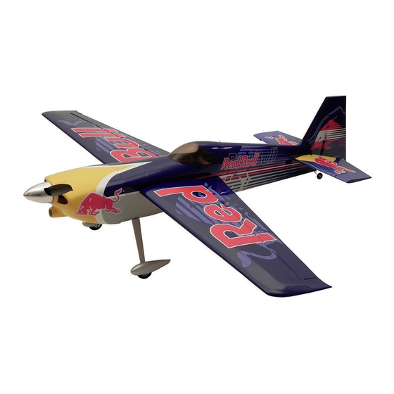
EDGE 540 RB
Fully licensed through
Red Bull GmbH
Austria
Please read the instruction manual carefully and take notice of the safety guidelines.
If the model is given to a third party, always include this instruction manual to the model.
The Flitework Gmbh assumes no liability in case of misprints. Technical amendments reserved.
INSTRUCTION MANUAL
FLWA4140 - Edge 540 RB 1,2 m
Designed in Austria - Made in China
Distributed by :
Technical data : Edge 540 RB
Wingspan
Lenght
Take off weight
Wing Area
Wing loading
Battery
RC Functions
www.hobbico.de
1 290 mm
1 150 mm
1 250 g
28 dm²
44,6 g/dm²
LiPo 3S 2200 mAh
Ailerons, elevator,
rudder, motor
Advertisement
Table of Contents

Subscribe to Our Youtube Channel
Related Manuals for Hobbico Edge 540 RB FLWA4140


Summary of Contents for Hobbico Edge 540 RB FLWA4140
-
Page 1: Instruction Manual
If the model is given to a third party, always include this instruction manual to the model. The Flitework Gmbh assumes no liability in case of misprints. Technical amendments reserved. Designed in Austria - Made in China www.hobbico.de Distributed by :... -
Page 2: Table Of Contents
Kit check ....................4 Set the Control Throws ............14 Spare parts ...................4 Check-List ..................14 Contenu du kit ..................5 Hobbico Service Line Europe ........... 14 Installing the elevator ..............6 Hobbico Service Line USA ............14 Elevator linkage .................7 Flitework Service Line..............14 Mounting the rudder ..............8... -
Page 3: Safety Precautions
SAFETY PRECAUTIONS ADDITIONAL ITEMS REQUIRED ❍ 1. Your Edge 540 1.2m should not be considered a toy, but rather a sophisticated, working model that functions very ❍ 1 x Motorset FW 3545/100 (Référence : FLWA8003) much like a full-size airplane. Because of its performance ❍... -
Page 4: Kit Check
If any parts are missing or are not of acceptable quality, or if you need assistance with assembly, contact Hobbico Product Support. Service center Revell GmbH Henschelstr. -
Page 5: Contenu Du Kit
CONTENU DU KIT Painted motor cowl Rudder 10 Linkage- and screw set Fuselage Wing set 11 Tail landing gear Canopy Carbon fiber wing joiner 460x13mm 12 Main wheels Elevator complete with connection Landing gear bows with axles bracket Wheel pants... -
Page 6: Installing The Elevator
INSTALLING THE ELEVATOR ❏ 1. Put the fleece hinges into the slots of the elevator flaps. ❏ 4. Check the correct placement, measuring the distance Mark the middle of the hinges with a permanent marker. Drill from elevator to a center point of the fuselage on both sides. 1.5mm holes into the marked spots of the flaps. -
Page 7: Elevator Linkage
❏ 10. Remove oozing epoxy glue with cotton buds and look, that the flap gaps are free of glue. ❏ 11. Is the epoxy glue hardened and are the flaps are movable smoothly, you can glue the fleece hinges with thin CAglue. -
Page 8: Mounting The Rudder
MOUNTING THE RUDDER ❏ 2. Put a servo extension cable (300-350mm) to the elevatorservo and fix the connectors with shrinking tube or ❏ 1. 18mm from the bottom of the rudder, drill a 2mm hole adhesive tape. for the tail gear. Make a small groove from the hole to the bottom of the rudder. -
Page 9: Rudder Linkage
RUDDER LINKAGE ❏ 1. Thread the steering wires into the fuselage, using a plastic bowden cable. The wires should be crossed inside the fuselage. ❏ 4. Roughen the steel wire on the adhesive surface and glue it with epoxy glue into the rudder. The wheel axis should be rectangular to the rudder flap. -
Page 10: Installing The Landing Gear
❏ 2. Screw the wheel together with the pants onto the aluminium landing gear bow. ❏ 5. Thread the steering wire into the eye bolts and the clamp sleeves. Adjust the wire so, that the eye bolt can easy reach the linkage carrier of the servo lever. -
Page 11: Installing The Motor
INSTALLING THE MOTOR ❏ 4. Bring the motor cowl in the correct position. Check the position with the spinner base plate. There should be a gap of ❏ 1. Screw the prop adapter and the aluminium cross to the 2mm between the cowling and the spinner. Fix the cowl with motor. -
Page 12: Mounting The Main Wings
❏ 7. On the bottom side of the fuselage you can cut out the opening for cooling air stream. MOUNTING THE MAIN WINGS ❏ 4. Hook the Z-cranked end of the linkage into the servo ❏ 1. Glue the ailerons into the wings, like you did with horn. -
Page 13: Installing The Battery
INSTALLING THE BATTERY CHECK THE CONTROL DIRECTIONS ❍ 1. Turn on the transmitter and receiver and center the As underlay of the battery, a anti-slip mat of the DIY-store is trims. If necessary, remove the servo arms from the servos very useful. -
Page 14: Set The Control Throws
Because of this, you may be more likely to overlook certain checks and procedures that should be HOBBICO SERVICE LINE EUROPE performed before the model is flown. To help avoid this, Service department Revell GmbH a checklist is provided to make sure these important Henschelstr. - Page 15 NOTES...
- Page 16 Flitework GmbH Tel: +43 664 3231059 Geymannstraße 27 Skype: flitework 4713 Gallspach Austria / Europe Mail.: office@flitework.at www.flitework.at...
Need help?
Do you have a question about the Edge 540 RB FLWA4140 and is the answer not in the manual?
Questions and answers