Table of Contents
Advertisement
WARRANTY
Hobbico guarantees this kit to be free from defects in both
material and workmanship at the date of purchase. This warranty
does not cover any component parts damaged by use or
modification. In no case shall Hobbico's liability exceed the
original cost of the purchased kit. Further, Hobbico reserves
the right to change or modify this warranty without notice.
In that Hobbico has no control over the final assembly or material
used for final assembly, no liability shall be assumed nor
accepted for any damage resulting from the use by the user of
the final user-assembled product. By the act of using the
user-assembled product, the user accepts all resulting liability.
If the buyer is not prepared to accept the liability associated
with the use of this product, the buyer is advised to return
READ THROUGH THIS MANUAL BEFORE STARTING CONSTRUCTION. IT CONTAINS IMPORTANT
INSTRUCTIONS AND WARNINGS CONCERNING THE ASSEMBLY AND USE OF THIS MODEL.
© 2015 Flyzone, a Hobbico company.
®
®
I N S T R U C T I O N M A N U A L
I N S T R U C T I O N M A N U A L
this kit immediately in new and unused condition to the
place of purchase.
To make a warranty claim send the defective part or item to
Hobby Services at the address below:
Hobby Services
3002 N. Apollo Dr. Suite 1
Champaign IL 61822 USA
Include a letter stating your name, return shipping address, as
much contact information as possible (daytime telephone
number, fax number, e-mail address), a detailed description of
the problem and a photocopy of the purchase receipt. Upon
receipt of the package the problem will be evaluated as quickly
as possible.
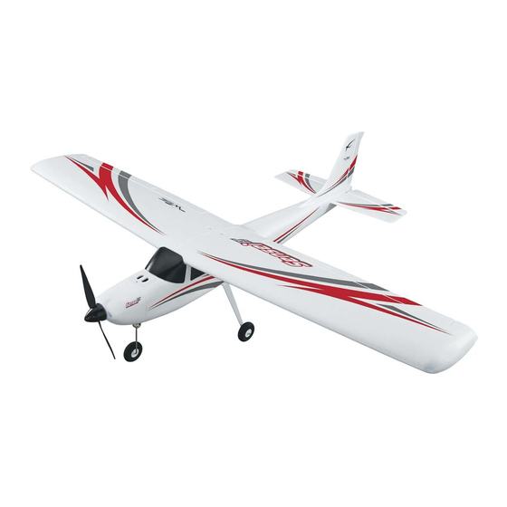
SPECIFICATIONS
SPECIFICATIONS
58 in
58 in
Wingspan:
Wingspan:
[1475mm]
[1475mm]
™
™
2
2
Wing
Wing
566 in
566 in
Area:
Area:
[36.5 dm
[36.5 dm
3.25 lb
3.25 lb
Weight:
Weight:
[1470 g]
[1470 g]
Wing
Wing
13 oz/ft
13 oz/ft
Loading:
Loading:
[40 g/dm
[40 g/dm
48 in
48 in
Length:
Length:
[1220 mm]
[1220 mm]
6-channel
6-channel
Radio:
Radio:
(required)
(required)
FLZA3030RTF/3034RxR Mnl
™
2
2
]
]
2
2
2
2
]
]
Advertisement
Table of Contents

Related Manuals for Hobbico Flyzone Sensei FS


Summary of Contents for Hobbico Flyzone Sensei FS
- Page 1 Hobby Services 3002 N. Apollo Dr. Suite 1 In that Hobbico has no control over the final assembly or material Champaign IL 61822 USA used for final assembly, no liability shall be assumed nor...
-
Page 2: Table Of Contents
For the latest technical updates or manual corrections to 2. You must assemble the model according to the the Sensei visit the Hobbico web site at www.hobbico. instructions. Do not alter or modify the model, as doing com. Open the “Airplanes” link, then select “Sensei”. If so may result in an unsafe or unfl... -
Page 3: Additional Items Required
1. Connect the input power to the charger. The GREEN LED ADDITIONAL ITEMS REQUIRED will be lit, indicating standby mode. The RED LED will be OFF. 2. Connect the battery to be charged to the balance plug. Radio Control System The RED LED will also be lit, and remain RED during the charging. -
Page 4: Ordering Replacement Parts
DESCRIPTION be provided by your hobby dealer or mail-order company. FLZA6166 Fuselage To locate a hobby dealer, visit the Hobbico web site at www. hobbico.com. Choose “Where to Buy” at the bottom of the menu FLZA6167 Wing Set on the left side of the page. Follow the instructions provided on... -
Page 5: Assemble The Sensei
ASSEMBLE THE SENSEI Install the Main Landing Gear ❏ 4. Insert the three guide posts into the three recesses in the top of the horizontal stabilizer. ❏ Attach the main landing gear to the fuselage using two 3x16mm sheet metal screws. Note that the landing gear is angled forward. -
Page 6: Connect The Rudder And Elevator Controls
❏ ❏ 6. Insert the 3 x 25mm machine screw into the hole in the 3. Re-install the 90° pushrod connector on the pushrod. bottom of the fuselage. Thread the 3 x 25mm machine screw Use needle-nose pliers to snap the 90° pushrod connector through the horizontal stabilizer and into the bottom of the onto the wire. -
Page 7: Install The Wing Joiner
Install the Wing Joiner ❏ 3. Insert the plastic wing connector in the top of the wing. Note that the connector is angled to match the angle of the top of the wing. When correctly installed, the connector should be fl ush with the top of the wing. ❏... -
Page 8: Rx-R Version
RX-R VERSION Install the Receiver All of the wires have been properly connected to the WISE gyro stabilization unit at the factory. All you need to do are the fi nal connections to your receiver. The connections shown in the following illustration are for channel assignments of Tactic and Futaba brand radio components. -
Page 9: Radio System
switch SE for ‘CTRL’. OFFSET should remain 0% and travel should be +100% for both values. ❏ 3. Position the throttle stick (left stick) to idle (all the way down) and switch on the transmitter. The power indicator light should be glowing a steady red. A fl ashing red light and an audible tone indicates low voltage. - Page 10 ❏ 6. You do not need to remove the receiver from the fuselage to bind it to the transmitter. Make sure the throttle stick is down in the idle position and the transmitter is switched ON. Insert a small screwdriver or paperclip through the hole marked “LINK” and press the pushbutton until the LED on the receiver glows red and then turns off after about one second.
-
Page 11: Check The Control Throws
Check the Control Throws One major factor that determines how an airplane handles in the air is the control surface throw, or how far each control surface (aileron, elevator and rudder) moves up and down or left and right. If the throw is too much, the plane will respond too quickly. -
Page 12: Check The Stabilization System
An LED light on the WISE gyro will indicate which stabilization mode is selected: Double-check that the 3-position fl ight mode switch corresponds to the expected fl ight mode as indicated by LED color on the WISE gyro. MODE LED COLOR BEGINNER BLUE INTERMEDIATE... -
Page 13: Mount The Propeller
❏ 3. Checking the rudder direction is different than the elevator and ailerons. The WISE gyro corrects heading by detecting sudden changes in yaw (the direction the nose is pointing). In ❏ 3. Install the spinner backplate on the prop adapter, followed order to check this, hold the plane level with one hand near the by the propeller, prop washer and prop nut. -
Page 14: Important Esc Information
❏ 3. If the Sensei does not balance between the lines, determine the amount of weight required to balance it by ❏ 2. On the underside of the wing there are plastic aileron placing segments of Great Planes stick-on weight (GPMQ4485) servo covers which have circular decals on them. -
Page 15: Wise Gyro Stabilization System
● The motor and ESC come already connected and the motor rotation should be correct. However, if you have to disconnect the ESC from the motor and when you reconnect it, the motor is rotating in the wrong direction, swapping any two of the three motor wires will change the direction of rotation of the motor. -
Page 16: Climb Assist
Climb Assist The WISE gyro is equipped with a climb assist function which automatically applies a small percentage of up elevator control for all throttle settings above 50%. The climb assist feature makes taking off virtually hands-free. At full throttle the WISE gyro will add enough elevator for a smooth, gradual lift off and will continue to climb as long as the throttle is above 50%. -
Page 17: Get The Model Ready To Fly
To range check the Tactic TTX610 radio control system, switch GET THE MODEL READY TO FLY on the transmitter and connect the motor battery to the ESC. Set the model on the ground and have an assistant hold the Identify Your Model model. -
Page 18: Takeoff
TAKEOFF The WISE gyro stabilization system will automatically add the CAUTION (THIS APPLIES TO ALL R/C AIRPLANES): If, necessary up elevator to lift off the runway and begin to climb while fl ying, you notice an alarming or unusual sound such as to a safe altitude. -
Page 19: Landing
LANDING Flare sitting in the cockpit. If you fi nd this diffi cult, try turning your rudder control appears backwards. Moving the stick to the back to the plane when it is fl ying toward you and watch the left will make it appear as if the plane is moving to the right plane by looking over your shoulder. -
Page 20: Improving Your Piloting Skills
If you have made any signifi cant trim changes (more than 4 clicks Improving Your Piloting Skills of one or more trim buttons), do not switch back to BEGINNER or INTERMEDIATE mode until after you have landed the plane. After you have made several fl ights in BEGINNER mode you can When landed, unplug the fl...
Need help?
Do you have a question about the Flyzone Sensei FS and is the answer not in the manual?
Questions and answers