Advertisement
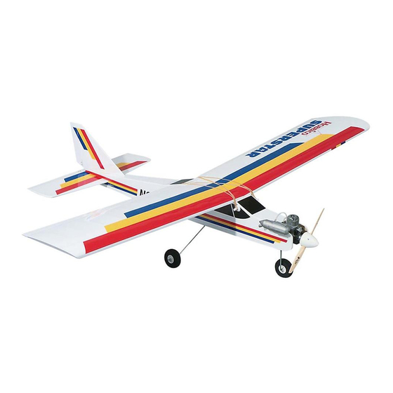
Wingspan: 60 in [1524mm]
Wing Area: 660 sq in [42.6dm
Weight: 5.5 lbs [2495g]
Wing Loading: 19 oz/ sq ft [58 g/dm
Engine: .40 cu in [6.5cc] two-stroke
Radio: 4-channel, 4 servos
Hobbico
®
guarantees this kit to be free from defects in both material and workmanship at the date of purchase. This warranty
does not cover any component parts damaged by use or modification. In no case shall Hobbico's liability exceed the original cost
of the purchased kit. Further, Hobbico reserves the right to change or modify this warranty without notice.
In that Hobbico has no control over the final assembly or material used for final assembly, no liability shall be assumed nor
accepted for any damage resulting from the use by the user of the final user-assembled product. By the act of using the
user-assembled product, the user accepts all resulting liability.
If the buyer is not prepared to accept the liability associated with the use of this product, the buyer is advised to return
this kit immediately in new and unused condition to the place of purchase.
READ THROUGH THIS MANUAL BEFORE STARTING CONSTRUCTION. IT CONTAINS IMPORTANT
INSTRUCTIONS AND WARNINGS CONCERNING THE ASSEMBLY AND USE OF THIS MODEL.
© Copyright 2002
2
]
2
]
See more of our products at www.hobbico.com
™
WARRANTY
1610 Interstate Drive Champaign, IL 61822
(217) 398-8970, Ext. 2
airsupport@hobbico.com
HCAZ3084 for HCAA2020 V:1.0
Advertisement
Table of Contents

Related Manuals for Hobbico Superstar 40 ARF


Summary of Contents for Hobbico Superstar 40 ARF
- Page 1 Further, Hobbico reserves the right to change or modify this warranty without notice. In that Hobbico has no control over the final assembly or material used for final assembly, no liability shall be assumed nor accepted for any damage resulting from the use by the user of the final user-assembled product. By the act of using the user-assembled product, the user accepts all resulting liability.
-
Page 2: Important Safety Precautions
AMA, the governing body of model aeronautics in the United States, provides insurance to Congratulations and thank you for purchasing the Hobbico members who comply with the Safety Code. You must be a SuperStar .40 ™... -
Page 3: Additional Items Required
to make the CA harden right away. Activator (also known as Additional Items Required “accelerator”) is usually sprayed out of a small bottle. One accessory recommended for applying CA is CA Applicator Tips (HCAR3780). These small tips fit on the top of the bottle and help direct and control the amount of CA that comes out. -
Page 4: Kit Inspection
Before beginning assembly, inspect the parts in this kit to make sure they are of acceptable quality. If any parts are defective or damaged, or if you need assistance with assembly, contact Product Support. Hobbico Product Support: Phone: (217) 398-8970 Fax: (217) 398-7721 E-mail: airsupport@hobbico.com When ready to fly, you’ll need the equipment to fuel the plane... -
Page 5: Parts List
Parts List 1. Wing 11. Plywood fuselage servo tray 2. Fuselage (nose gear factory installed) 12. Plywood wing joiners 3. Fin with rudder 13. 2" spinner 4. Stabilizer with elevator 14. These parts not used 15. Hardware (see detailed list below) 5. -
Page 6: Assemble The Wing
Assemble the Wing Hinge the Ailerons Start with the right wing first. 1. Carefully remove the masking tape holding the aileron to the wing. Also remove the protective foam block on the aileron torque rod. 5. Remove the aileron from the wing and take out the hinges. - Page 7 3. Lay one wing panel flat on your workbench. Measure the distance between the bottom of the raised end of the wing and the workbench. The measurement should be 3-1/4" to 4-1/4" [80mm to 110mm]. 9. Position the aileron so there is a small gap between the aileron and the wing–just enough to see light through or to slip a piece of paper through.
- Page 8 3. Use wire cutters to cut two of the arms off a four-arm servo arm. Install the arm on the aileron servo. 4. Drill 1/16" [1.6mm] holes through the servo mount for the servo mounting screws, then temporarily mount the servo using 7.
-
Page 9: Assemble The Fuselage
2. Mount the wheels to the landing gear with a 5/32" wheel collar on both sides of each wheel. Add a small drop of non- permanent thread locking compound (such as Great Planes Threadlocker GPMR6060) to two 6-32 set screws and thread 7. - Page 10 Mount the Stab and Fin 1. Use 30-minute epoxy to securely glue in the 1/4" [6mm] wing dowels. The longer dowel goes in front. After positioning the dowels, lightly coat them with epoxy so they will be fuelproofed. 4. Use a fine-point felt-tip pen to mark both ends of the stab where the leading edge meets the tip under the covering.
- Page 11 into the balsa beneath. Cutting too deep will weaken the structure, possibly causing the stab to break during flight. An alternate way to cut the covering over the stabilizer is to use a soldering iron. This way, you will not risk accidentally cutting into the balsa.
- Page 12 followed by the metal plates and the screw. Bend one of the tubes upward so it will be near the top of the tank when the stopper is inserted. This tube will be connected to the muffler and serves both as an overflow line (to signify when the tank is full) and as a pressure line to provide muffler pressure to the tank.
- Page 13 3. Guide the tubes through the holes up through the fuselage into the radio compartment. 9. Mount the radio tray in the fuselage with the #2 x 3/8" [10mm] screws. Mount the Servos 1. Make two 18" [460mm] pushrod tubes from the 3/16" [4.8mm] gray pushrod tubes supplied with this kit.
- Page 14 arm, to a hole that is as close to 17/32" [13mm] as possible). mounting the horn. Mount the horn with two 2-56 x 1/2" [13mm] Secure the connector with a nylon retainer. screws and the mounting plate. 7. Place the servos in the servo tray as shown in the photo at step 5.
- Page 15 the servo tray as shown. Use thin or medium CA to glue the pushrod tubes to the brace and the fuselage where they exit. Let’s hook up the throttle... 17. Cut a 12" [300mm] pushrod tube from any remaining 3/16" [4.8mm] gray pushrod tubing. Roughen one end of the tube with coarse sandpaper so glue will adhere.
-
Page 16: Prepare The Model For Flight
Prepare the Model for Flight The batteries must be charged to continue. Check the Control Directions The first thing that has to be done is to center the controls and make sure they all move in the right direction. 1. Connect the aileron servo wire coming from the wing to 4. - Page 17 Note that pulling the elevator stick back moves the elevator up (which, in flight, pushes the tail down, thus increasing the angle of the wing thereby making the model climb). The best way to keep this in mind is to think in terms of a pilot in an airplane.
- Page 18 Control Throws Chart: Ailerons: 7/16" [11mm] up 7/16" [11mm] down Elevator: 1/2" [13mm] up 1/2" [13mm] down Rudder: 1" [25mm] right 1" left [25mm] left 1. With the transmitter and receiver on, move the throttle trim lever and the throttle stick all the way down. Rotate the arm on the carburetor to fully close the carburetor.
- Page 19 on the landing gear as shown. If the model does not sit level, 4. If you are not able to achieve these settings, more or less or, if after a hard landing the main landing gear has bent movement may be required from the throttle pushrod. The upward, remove the main landing gear and use a bench vise same as the control surface throws, this is done by relocating or pliers to bend it back down to achieve the correct ground...
- Page 20 Check List Now it’s time to do a final check before taking the model to the field. Take the time now to do these checks and make certain your model is ready to fly. 1. Make sure the screws on all the wheel collars are fully tightened.
-
Page 21: Preflight Checks
Mount the Wing adequate operational range. Mount the wing to the fuselage with 12 #64 Hobbico or similar rubber bands. Install them from front to back, crisscrossing 1. Turn on the transmitter and receiver. Leave the transmitter the last two. -
Page 22: Engine Safety Precautions
by the model and tell you what the controls are doing to confirm Flying that they operate correctly. You should be able to walk approximately 100 feet from the model and still have control The following flying instructions are in no way an endorsement without any “glitching”... - Page 23 If going too fast, smoothly advance the throttle “Where to Buy.” If this kit is missing parts, contact Hobbico and allow the model to gain airspeed, then apply elevator to Product Support.
- Page 24 BUILDING NOTES Kit Purchased Date: _______________________ Date Construction Finished: _________________ Where Purchased:_________________________ Finished Weight: __________________________ Date Construction Started: __________________ Date of First Flight: ________________________ FLIGHT LOG...
Need help?
Do you have a question about the Superstar 40 ARF and is the answer not in the manual?
Questions and answers