Table of Contents
Advertisement
Quick Links
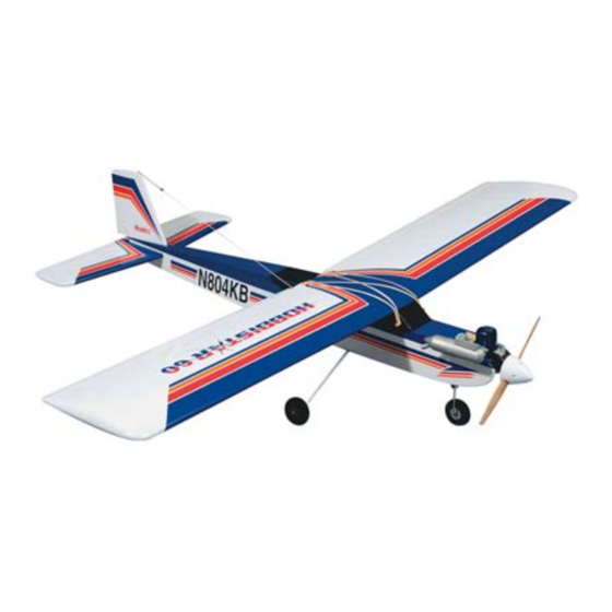
ALMOST READY-TO-FLY RADIO CONTROLLED MODEL AIRPLANE
-
ALL AIRFRAME PARTS ARE FACTORY ASSEMBLED FOR PERFECT ALIGNMENT AND
QUICK ASSEMBLY.
-
ALL PRE-ASSEMBLED COMPONENTS ARE FACTORY COVERED.
•
CLASSIC DESIGN WITH DURABLE BALSA AND PLYWOOD CONSTRUCTION.
•
SEMI-SYMMETRICAL AIRFOIL GIVES THE HOBBISTAR 60 AEROBATIC CAPABILITIES.
ENTIRE CONTENTS © 1990,
V1.0
Advertisement
Table of Contents

Subscribe to Our Youtube Channel
Related Manuals for Hobbico Hobbistar 60


Summary of Contents for Hobbico Hobbistar 60
- Page 1 ALL AIRFRAME PARTS ARE FACTORY ASSEMBLED FOR PERFECT ALIGNMENT AND QUICK ASSEMBLY. ALL PRE-ASSEMBLED COMPONENTS ARE FACTORY COVERED. • CLASSIC DESIGN WITH DURABLE BALSA AND PLYWOOD CONSTRUCTION. • SEMI-SYMMETRICAL AIRFOIL GIVES THE HOBBISTAR 60 AEROBATIC CAPABILITIES. ENTIRE CONTENTS © 1990, V1.0...
- Page 2 If the Hobbistar 60 is not quite what you expected, return it to your dealer in New and Unused condition. However, we think you will agree with us that the Hobbistar 60 kit is one of the finest models of its type and will offer you many hours of enjoyment.
-
Page 3: Table Of Contents
PARTS LIST Before assembly match the parts in the exploded view of the Hobbistar with the parts in the kit. Check off each part on the parts list. If any parts are missing or damaged return the kit to your hobby dealer. R i g h t W i n g ................ -
Page 4: Wing Joiners
PRE-ASSEMBLY Locate the #4 vertical stabilizer and #5 horizontal stabilizer. The Locate part #6 wing joiners. Join the three wing joiners together rudderis temporarily attached to the vertical stabilizer. The elevator using a light coat of epoxy. They should form a "V" shape as shown is temporarily attached to the horizontal stabilizer. - Page 5 10. Remove the aileron and apply epoxy to the hinges and the part of the Using the same procedure for epoxying the hinges that was used in torque rod that is inserted into the aileron. Also force a small amount Step 6, epoxy the three hinges into the horizontal stabilizer.
- Page 6 WING JOINER INSTALLATION When you are satisfied with the fit of the wing joiner, remove the Using the wing joiner assembled in Step 1 of pre-assembly, insert wings from the joiner. Mix a batch of 30 minute epoxy and using the the wing joiner into the wing panel temporarily.
-
Page 7: Aileron Servo
Note: You may proceed with fuselage preparation and come back to here after the wing is ready. Remove the servo tray and, following the picture, remove the 7. After the epoxy has fully cured (overnight) remove the masking tape covering from area "A". and apply the blue center tape. -
Page 8: Main Landing Gear
FUSELAGE PREPARATION The elevator exit hole is located on the left side of the fuselage, On the side at the rear of the fuselage use your finger to locate the 61/2" forward of the tail post and approximately 1 inch above the stabilizer cutouts. - Page 9 HORIZONTALSTABILIZER IMPORTANT: This next series of steps will determine how well your Hobbistar 60 will fly. So please read and reread these steps so that you are totally familiar with its sequence. Locate the horizontal stabilizer. Slide the stabilizer into the slot prepared in the previous section.
- Page 10 INSTALLATION OF VERTICAL STABILIZER Now if we have done a good job with the wing-stabilizer relationship, the installation of the rudder should be easy. The vertical stablilizer is 90' to the wing. A drafting triangle would be helpful here. 4. Using the same scrap of plywood, apply an even coat of epoxy to the top and bottom of the horizontal stabilizer in the area where you removed the covering.
-
Page 11: Main Landing Gear Installation
MAIN LANDING GEAR INSTALLATION 3. If using the Snap 'R' Keeper make a 90" bend 5/16" from the end of the 17 3/4" control rod as shown. If using the E-Z connector, install the connector on the bottom of the nose gear control horn following Place a small bead of silicone sealant in the groove, then insert the the manufacturer's instructions. -
Page 12: Engine Installation
ENGINE INSTALLATION 4. Make a "z" bend in the 17 3/4" throttle control rod and install on the Temporarily install the two mounting pads to the engine mount using throttle arm of engine. Next, cut one white tube so it is 9" long. Rough four 4mm x 15mm screws. -
Page 13: Fuel Pipe
RADIO INSTALLATION Wrap the fuel tank with natural foam to insulate it from vibration. 1. Using your radio switch as a guide, make the necessary opening for Install the fuel tank so that the cap is through the hole in the firewall. mounting the switch on the left side of the fuselage, as viewed from above looking toward the engine, and 2"... -
Page 14: Clevis
CONTROL HORN INSTALLATION Plug the servos and switch into the receiver and the receiver battery into the switch. Then wrap the receiver and the receiver battery in Caution: When installing control horns the center line of the control natural foam. Use the rubber bands to loosely hold the foam in place. horn holes must be the same as the center line of the hinge joint. -
Page 15: Radio Installation
CONTROL ROD ADJUSTMENT RADIO INSTALLATION 1. Be sure that your radio system is fully charged and the servos are 4. If using the Snap 'R' Keeper mark on the push rods where the hole plugged into the receiver. Turn on the transmitter then receiver. Set in the servo arm is. -
Page 16: Aileron Servo Installation
AILERON SERVO INSTALLATION Drill a 1/16" hole in the side of the fuselage and the upper portion of the vertical stabilizer. Install the strain relief close to the receiver. Route Route the servo wire through the side of the tray as shown. Using the receiver antenna through the holes as shown. -
Page 17: Engine Maintenance
STARTING ENGINE Engine Maintenance Always check the engine mounting bolts, muffler, glow plug, propeller and Turn the radio on and open the throttle to full open Place your finger spinner, etc., before attempting to start the engine. Check for loose bolts, over the air intake on the carburetor while turning the prop counter nuts or screws which may come off when the engine is running and cause clockwise a few time? Notice the fuel line It no fuel is reaching the... - Page 18 On the ground, the rudder is more effective. A transition will need to be made once the plane Fully Assembled Hobbistar 60 leaves the ground. That transition, from using the rudder on the ground to using the ailerons once it leaves the ground, will take a little practice.
-
Page 19: Your First Flight
YOUR FIRST FLIGHT Hobbico Inc. is proudly known as being the nation's number ONE Pre-Flight Checklist supplier for ARF type airplane kits. Below are a few of the fine kits that are available from your dealer. Before leaving for the flying field go through the pre-flight checklist This will help prevent you from forgetting to take things with you. - Page 20 ASAP AIRPLANE KITS HCAA2580 - Telstar 40 HCAA2050 - Flightstar 40 HCAA2520 - Telstar 25 HCAA2530 - Cherekee 25 HCAA2600 - Extra 300 HCAA2590-Cessna 182 Inc. Entire contents © 1990, - 2 0 -...
Need help?
Do you have a question about the Hobbistar 60 and is the answer not in the manual?
Questions and answers