Table of Contents
Advertisement
Quick Links
Advertisement
Table of Contents

Related Manuals for ADLINK Technology PCI-7200


Summary of Contents for ADLINK Technology PCI-7200
- Page 1 PCI-7200 / cPCI-7200 12MB/S High Speed Digital Input/ Output Card...
- Page 3 Trademarks PCI-7200 and cPCI-7200 are registered trademarks of ADLink Technology Inc., Other product names mentioned herein are used for identification purposes only and may be trademarks and/or registered trademarks of their respective...
-
Page 4: Table Of Contents
Installation ........5 What You Have..............5 Unpacking .................6 Device Driver Installation for Windows 95 .......6 PCI-7200’s Layout .............8 PCI-7200 Installation Outline .......... 10 2.5.1 Hardware configuration ......... 10 2.5.2 Slot selection............10 2.5.3 Installation Procedure ..........10 2.5.4 Running the 7200UTIL.EXE........11 Connector Pin Assignment .......... - Page 5 CHAPTER 4 Operation Theorem ..... 23 4.1 Direct Program Control ............23 4.2 Timer Pacer Mode............... 24 4.3 External Trigger ..............26 4.4 Handshaking............... 27 4.5 Timing Characteristic ............29 CHAPTER 5 C/C++ & DLL Libraries ....33 Installation............... 33 5.1.1 Installation ..............
- Page 6 5.26 _7200_DO_DMA_Status ..........64 5.27 _7200_DO_DMA_Stop............. 65 5.28 _7200_DI_Timer............... 66 5.29 _7200_DO_Timer............. 68 CHAPTER 6 Double Buffer Mode Principle..71 CHAPTER 7 Limitation ........73 Appendix A. 8254 Programmable Interval Timer ............75 The Intel (NEC) 8254............75 The Control Byte ............. 76 Mode Definition ...............
-
Page 8: How To Use This Guide
How to Use This Guide This manual is designed to help you use the PCI-7200 and cPCI-7200. The functionality of PCI-7200 and cPCI-7200 are the same except that cPCI-7200 has 4 auxiliary digital input and output. Therefore, the “PCI- 7200” represents both PCI-7200 and cPCI-7200 if not specified. -
Page 10: Chapter 1 Introduction
The PCI-7200 performs high-speed data transfers using bus mastering DMA via 32-bit PCI bus architecture. The maximum data transfer rates can be up to 12MB per second. It is very suitable for interface between high speed peripherals and your computer system. -
Page 11: Applications
• Digital pattern generator • Waveform and pulse generation • BCD interface driver 1.2 Features The PCI-7200 high-speed DIO Card provides the following advanced features: • 32 TTL digital input channels • 32 TTL digital output channels • Transfer up to 12M Bytes per second •... -
Page 12: Specifications
1.3 Specifications ♦ Digital I/O (DIO) • Channel: 32 TTL compatible inputs and outputs • Device: TTL74F273 and TTL74F373 • FIFO: 8 words (32-bit) (for PCI-7200) 2K + 8 words (32-bit) (for cPCI-7200) • Input Voltage: Low: Min. 0V; Max. 0.8V High: Min. - Page 13 • Storage Temperature: -20° C ~ 80° C • Humidity: 5 ~ 95%, non-condensing • Connector: PCI-7200: one 37-pin D-type and one 40-pin ribbon connector cPCI-7200: one 100-pin SCSI-type connector • Dimension: PCI-7200: Compact size, only 98mm (H) X 147mm (L)
-
Page 14: Chapter 2 Installation
Installation This chapter describes how to install the PCI-7200. At first, the content of the package and the unpacking information that you should be careful are described. Because the PCI-7200 is a plug and play device, there is no more jumper or DIP switch setting for configuration. The Interrupt number and I/O port address are assigned by the system BIOS during system boot up. -
Page 15: Unpacking
You are now ready to install your PCI-7200. 2.3 Device Driver Installation for Windows 95 While you first plug PCI-7200 card and enter Windows 95, the system will detect this device automatically and show the following dialog box that prompts you to select the device information source. - Page 16 Place ADLink’s “Manual & Software Utility” CD into the appropriate CD driver. Type “X:\Software\NuDAQPCI\7200\Win95” in the input field (X indicates the CD ROM driver) and then click OK. The system will start the installation of PCI-7200. Installation • • 7...
-
Page 17: Pci-7200'S Layout
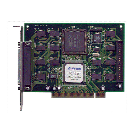
2.4 PCI-7200’s Layout Figure 2.1 PCI-7200 Layout Diagram 8 • • Installation... - Page 18 Figure 2.1a PCI-7200 Layout Diagram Installation • • 9...
-
Page 19: Pci-7200 Installation Outline
CompactPCI peripheral slot. 7. Secure the PCI-7200 in place at the rear panel of the system unit using screw removed from the slot (for PCI-7200), or screw the cPCI-7200 in place at the front panel of the CompactPCI system. -
Page 20: Running The 7200Util.exe
By using the 7200UTIL.EXE, you can get the above values and they are displayed by this utility. A testing program is included in this utility, you can check if your PCI-7200 can work properly. Refer Section 5.2 for further detailed information. 2.6 Connector Pin Assignment 2.6.1 PCI-7200 Pin Assignment... - Page 21 DI 16 DO16 DI 17 DO17 DI 18 DO18 DI 19 DO19 DI 20 DO20 DI 21 DO21 DI 22 DO22 DI 23 DO23 DI 24 DO24 DI 25 DO25 DI 26 DO26 DO27 DI 27 DI 28 DO28 DO29 DI 29 DI 30 DO30...
-
Page 22: Cpci-7200 Pin Assignment
2.6.2 cPCI-7200 Pin Assignment (1) DO0 (26) O_TRG (51) DO1 (76) GND (51) (52) (2) DO2 (27) O_REQ (52) DO3 (77) GND (53) (3) DO4 (28) O_ACK (53) DO5 (78) GND (4) DO6 (29) AUXIN2 (54) DO7 (79) AuxOut2 (5) DO8 (30) AUXIN3 (55) DO9 (80) AuxOut3 (6) DO10... - Page 23 The internal timer/counter 8254 on the PCI-7200 is configured as above diagram (figure 2.4). User can use it to generate the timer pacer for both digital input and digital output trigger. The digital input timer pacer is from OUT0 (Timer 0), and the digital output timer pacer is from OUT1 (Timer 1).
-
Page 24: Chapter 3 Register Structure & Format
Register Structure & Format 3.1 I/O Registers Format The PCI-7200 occupies 8 consecutive 32-bit I/O addresses in the PC I/O address space and the cPCI-7200 occupies 9 consecutive 32-bit I/O addresses. Table 4.1 shows the I/O Map Address Read Write... -
Page 25: Digital Input Register (Base + 10)
3.2 Digital Input Register (BASE + 10) 32 digital input channels can be read from this register Address: BASE + 10 Attribute: READ Only Data Format: Byte Base +10 Base +11 DI15 DI14 DI13 DI12 DI11 DI10 Base +12 DI23 DI22 DI21 DI20... -
Page 26: Dio Status & Control Register (Base + 18)
3.4 DIO Status & Control Register (BASE + 18) The data transfer mode of digital input is controlled and status is checked through this register. Address: BASE + 18 Attribute: READ/WRITE Data Format: Byte Base +18 O_ACK DIN_EN I_TRG TRGPL I_FIFO I_TIME0 I_REQ I_ACK... - Page 27 1: I_TRG is Rising Edge Active 0: I_TRG is Falling Edge Active I_TRG: External Trigger Enable 1: Wait until I_TRG signal is active, digital input sampling will begin after a rising or falling edge of I_TRG is coming. 0: Start input sampling immediately (if input control register is set) DIN_EN: Digital Input Enable 1: Digital Input Enable...
-
Page 28: Interrupt Status & Control Register (Base + 1C)
O_TRG: Digital Output Trigger Signal This bit is used to control the O_TRG output of PCI-7200, the signal is on CN1 pin 36 of PCI-7200 or CN1 pin 26 of cPCI-7200 when 1: O_TRG 1 goes High (1) 0: O_TRG 1 goes Low (0) ♦... - Page 29 ♦ ♦ Interrupt Control: In PCI-7200, the interrupt can be triggered by many signal sources such as O_ACK, I_REQ, timer 0, timer 1, and timer 2. The interrupt source is controlled by the following bits: IO_ACK: Interrupt is triggered by O_ACK signal.
- Page 30 ISR. ♦ ♦ Timer Configuration Control: The 8254 timer on the PCI-7200 can be configured as either timer 0 cascaded with timer 2 or timer 1 cascaded with timer2. These configuration are controlled by the following bits:...
- Page 31 ♦ ♦ I_REQ Polarity Selection: When the input sampling is controlled by the I_REQ signal only, the I_REQ can be programmed to be rising edge active or falling edge active. REQ_NEG: I_REQ trigger polarity 1: latch input data on falling edge of I_REQ 0: latch input data on rising edge of I_REQ ♦...
-
Page 32: Chapter 4 Operation Theorem
Operation Theorem In PCI-7200, there are four data transfer modes can be used for digital I/O access and control, these modes are: 1. Direct Program Control: the digital inputs and outputs can be read/written and controlled by its corresponding I/O port address directly. -
Page 33: Timer Pacer Mode
The digital OUT operation is: outport (BASE+14, 0xAAAAAAAA ) // (A : 0 ~ F) The digital IN operation is: value = inport (BASE+10) // The input status is save in the // value variable 4.2 Timer Pacer Mode The digital I/O access control is clocked by timer pacer, which is generated by a interval programming timer/counter chip 8254. - Page 34 The operation sequences are: 1. Define the frequency (timer pacer rate) 2. The digital input data are saved in FIFO after a timer pacer pulse is generated. The sampling is controlled by timer pacer. 3. The data saved in FIFO will be transferred to main memory of your computer system directly and automatically.
-
Page 35: External Trigger
4.3 External Clock Mode The digital input is clocked by external strobe, which is from the Pin 19 (I_REQ) of CN2 (PCI-7200) or Pin 24 of CN1 (cPCI-7200). The operation sequence is very similar to Timer Pacer Trigger. The only difference is the clock source. -
Page 36: Handshaking
4.4 Handshaking In PCI-7200, it also supports a handshaking digital I/O transfer mode. That is, after input data is ready, an I_REQ is sent form external device, and I_ACK will go high to acknowledge the data already accessed. I_REQ & I_ACK for Digital Input 1. - Page 37 O_REQ & O_ACK for Digital Output 1. Digital Output Data is moved from PC memory to FIFO of PCI- 7200 by using DMA data mastering data transfer. 2. Move output data from FIFO to digital output circuit. 3. Output data is ready. 4.
-
Page 38: Timing Characteristic
4.5 Timing Characteristic 1. I_REQ as input data strobe (Rising Edge Active) I_REQ IN_REQ valid data valid data DI0~DI31 60ns 60ns 5 PCI CLK Cycle 30ns 2. I_REQ as input data strobe (Falling Edge Active) IN_REQ I_REQ valid data valid data DI0~DI31 60ns 60ns... - Page 39 3. I_REQ & I_ACK Handshaking IN_REQ I_REQ IN_ACK I_ACK valid data valid data DI0~DI31 2 PCI CLK Cycle 60ns 1 PCI CLK Cycle 4. O_REQ as output data strobe OUT_REQ O_REQ D00~D031 valid data valid data 500ns 19ns 2 PCI CLK Cycles 30 •...
- Page 40 5. O_REQ & O_ACK Handshaking OUT_REQ O_REQ OUT_ACK O_ACK valid data valid data DO0~Do31 5 PCI CLK Cycle 1 PCI CLK Cycle 19ns Note: O_ACK must be de-asserted before O_REQ asserts, O_ACK can be asserted any time after O_REQ asserts, O_REQ will be reasserted after O_ACK is asserted.
-
Page 42: Chapter 5 C/C++ & Dll Libraries
X:\> CD NUDAQPCI\7200\DOS X:\NUDAQPCI\7200\DOS> SETUP 4. An installation complete message will be shown on the screen. After installation, all the files of PCI-7200 Library & Utility for DOS are stored in C:\ADLink\7200\DOS directory. C/C++ & DLL Libraries • • 33... - Page 43 2. If autorun setup program is not invoked automatically please execute X:\setup.exe. (X indicates the CD-ROM drive) 3. Select NuDAQ PCI >> Drivers >> Win 95/98 >> PCI-7200 to setup PCI-7200 DLL for Windows 95. After a welcome dialog box, Setup prompts the following dialog box for you to specify the destination directory.
-
Page 44: Running Testing Utility (7200Util.exe)
5.2 Running Testing Utility (7200UTIL.EXE) After finishing the installation of PCI-7200 DOS software, you can execute the utility by the following commands under DOS environment: C> cd \ADLINK\7200\DOS\UTIL C> 7200UTIL The following diagram will be displayed on you screen. You can test the functionality : 1. -
Page 45: Software Driver Naming Convention
Windows library, A capital "W" is put on the head of each function name of the Windows DLL driver. e.g. W_7200_Initial () There are 21 function calls provided by each driver for PCI-7200 Digital I/O cards; all drivers (DOS, Win-95/98) provide the same function capability. - Page 46 @ Syntax Visual C++ (Windows 95/98) int W_7200_Initial (U8 card_number, U16 *base_addresss, U8 *irq_no) Visual Basic (Windows 95/98) W_7200_Initial (ByVal card_number As Byte, base_addresss As Integer, irq_no As Byte) As Long C/C++ (DOS) int _7200_Initial (U8 card_number, U16 *base_addresss, *irq_no) @ Argument card_number : the card number to be initialized, only four cards can be initialized, the card number must be...
-
Page 47: 7200_Switch_Card_No
5.5 _7200_Switch_Card_No @ Description After initialized more than one PCI-7200 cards, this function is used to select which card is used currently. @ Syntax Visual C++ (Windows 95/98) int W_7200_Switch_Card_No (U8 card_number) Visual Basic (Windows 95/98) W_7200_Switch_Card_No (ByVal card_number As Byte) As Long... -
Page 48: 7200_Aux_Di
5.6 _7200_AUX_DI @ Description Read data from auxiliary digital input port of cPCI-7200 card. You can get all 4 bits input data by using this function. @ Syntax Visual C++ (Windows 95/98) int W_7200_AUX_DI (U32 *aux_di) Visual Basic (Windows 95/98) W_7200_DI (aux_di As Long) As Long C/C++ (DOS) int _7200_DI (U32 *aux_di) -
Page 49: 7200_Aux_Di_Channel
5.7 _7200_AUX_DI_Channel @ Description Read data from auxiliary digital input channel of cPCI-7200 card. There are 4 digital input channels on the cPCI-7200 auxiliary digital input port. When performs this function, the auxiliary digital input port is read and the value of the corresponding channel is returned. * channel means each bit of digital input port. -
Page 50: 7200_Aux_Do
5.8 _7200_AUX_DO @ Description Write data to auxiliary digital output port. There are 4 auxiliary digital outputs on the cPCI-7200. @ Syntax Visual C++ (Windows 95/98) int W_7200_AUX_DO (U32 aux_do) Visual Basic (Windows 95/98) W_7200_AUX_DO (ByVal aux_do As Long) As Long C/C++ (DOS) int _7200_AUX_DO (U32 aux_do) @ Argument... -
Page 51: 7200_Aux_Do_Channel
5.9 _7200_AUX_DO_Channel @ Description Write data to auxiliary digital output channel (bit). There are 4 auxiliary digital output channels on the cPCI-7200. When performs this function, the digital output data is written to the corresponding channel. l channel means each bit of digital input port @ Syntax Visual C++ (Windows 95/98) int W_7200_AUX_DO_Channel (U8 do_ch_no, Boolean aux_data) -
Page 52: 7200_Di
5.10 _7200_DI @ Description This function is used to read data from digital input port. There are 32-bit digital inputs on the PCI-7200. You can get all 32 input data from _7200_DI by using this function. @ Syntax Visual C++ (Windows 95/98) -
Page 53: 7200_Di_Channel
@ Description This function is used to read data from digital input channels (bit). There are 32 digital input channels on the PCI-7200. When performs this function, the digital input port is read and the value of the corresponding channel is returned. -
Page 54: 7200_Do
5.12 _7200_DO @ Description This function is used to write data to digital output port. There are 32 digital outputs on the PCI-7200. @ Syntax Visual C++ (Windows 95/98) int W_7200_DO (U32 do_data) Visual Basic (Windows 95/98) W_7200_DO (ByVal do_data As Long) As Long... -
Page 55: 7200_Do_Channel
5.13 _7200_DO_Channel @ Description This function is used to write data to digital output channels (bit). There are 32 digital output channels on the PCI-7200. When performs this function, the digital output data is written to the corresponding channel. l channel means each bit of digital input port... -
Page 56: 7200_Alloc_Dma_Mem
5.14 _7200_Alloc_DMA_Mem @ Description Contact Windows 95/98 system to allocate a block of contiguous memory for single-buffered DMA transfer. This function is only available in Windows 95/98 version. @ Syntax Visual C++ (Windows 95/98) int W_7200_Alloc_DMA_Mem (U32 *buff, U32 *handle, U32 buf_size, U32 *actual_size) Visual Basic (Windows 95/98) W_7200_Alloc_DMA_Mem (buff As Long, handle As Long, ByVal... - Page 57 actual_size: The actual size system allocate for DMA memory. The unit is BYTE. If system is not able to get a block of contiguous memory of specified buf_size, it will allocate a block of memory as large as it can. In this case, this function...
-
Page 58: 7200_Free_Dma_Mem
5.15 _7200_Free_DMA_Mem @ Description Deallocate a system DMA memory under Windows 95/98 environment. This function is only available in Windows 95/98 version. @ Syntax Visual C++ (Windows 95/98) int W_7200_Free_DMA_Mem (U32 handle) Visual Basic (Windows 95/98) W_7200_Free_DMA_Mem (ByVal handle As Long ) As Long @ Argument handle: The handle of system DMA memory to deallocate. -
Page 59: 7200_Alloc_Dbdma_Mem
5.16 _7200_Alloc_DBDMA_Mem @ Description Contact Windows 95/98 system to allocate a block of contiguous memory as circular buffer for double-buffered DMA DI transfer. This function is only available in Windows 95/98 version. For double-buffered transfer principle, please refer to Section 6 “Double Buffered Mode Principle”. -
Page 60: 7200_Free_Dbdma_Mem
5.17 _7200_Free_DBDMA_Mem @ Description Deallocate a system circular buffer DMA memory under Windows 95/98 environment. This function is only available in Windows 95/98 version. For double-buffered transfer principle, please refer to Section 6 “Double Buffered Mode Principle”. @ Syntax Visual C++ (Windows 95/98) int W_7200_Free_DBDMA_Mem (U32 handle) Visual Basic (Windows 95/98) W_7200_Free_DBDMA_Mem (ByVal handle As Long ) As Long... -
Page 61: 7200_Di_Dma_Start
64K max. groups. PCI-7200 bus mastering works as follows: 1. To set up bus mastering, first do all normal PCI-7200 initialization necessary to control the board in status mode. This includes testing for the presence of the PCI BIOS, determining the base addresses, slot number, vendor and device ID's, I/O or memory, space allocation, etc. - Page 62 (not long words!) transferred during the bus master operation and can be a large number up to 64 million (2^26) bytes. Since the PCI-7200 transfers are always long words, this is 16 million long words (2^24). 3. After the input sampling is started, the input data is stored in the FIFO of PCI controller.
- Page 63 @ Syntax Visual C++ (Windows 95/98) int W_7200_DI_DMA_Start (U8 mode, U32 count, U32 handle, Boolean wait_trg, U8 trg_pol, Boolean clear_fifo, Boolean disable_di) Visual Basic (Windows 95/98) W_7200_DI_DMA_Start (ByVal mode As Byte, ByVal count As Long, ByVal handle As Long, ByVal wait_trg as Byte, ByVal trg_pol As Byte, ByVal clear_fifo As Byte, ByVal disable_di As Byte) As Long C/C++ (DOS)
- Page 64 di_buffer (DOS): If double buffer mode is disabled, this is the start address of the memory buffer to store the DI data. If double buffer mode is enabled, this memory buffer is actually of no use. But the buffer size still must be larger than the number of count (that is, count*4 bytes).
-
Page 65: 7200_Di_Dma_Status
5.19 _7200_DI_DMA_Status @ Description Since _7200_DI_DMA_Start function executed background, you can issue this function to check its operation status. This function only works when double-buffer mode is set as disable. @ Syntax Visual C++ (Windows 95/98) int W_7200_DI_DMA_Status (U8 *status, U32 *count) Visual Basic (Windows 95/98) W_7200_AD_Status (status As Byte, count As Long ) As Long C/C++ (DOS) -
Page 66: 7200_Di_Dma_Stop
5.20 _7200_DI_DMA_Stop @ Description This function is used to stop the DMA data transferring. After executing this function, the _7200_DI_DMA_Start function is stopped. The function returns the number of the data which has been transferred, no matter if the digital input DMA data transfer is stopped by this function or by the DMA terminal count ISR. -
Page 67: 7200_Dblbuffermode
5.21 _7200_DblBufferMode @ Description This function is used to enable or disable double buffer mode for DMA DI operation. @ Syntax Visual C++ (Windows 95/98) int W_7200_DblBufferMode (Boolean db_flag) Visual Basic (Windows 95/98) W_7200_DblBufferMode (ByVal db_flag As Byte) As Long C/C++ (DOS) int _7200_CheckHalfReady (Boolean db_flag) @ Argument... -
Page 68: 7200_Checkhalfready
5.22 _7200_CheckHalfReady @ Description When you use _7200_DI_DMA_Start to sample digital input data and double buffer mode enable. must _7200_CheckHalfReady to check data ready (data half full) or not in the circular buffer, and using _7200_DblBufferTransfer to get data. @ Syntax Visual C++ (Windows 95/98) int W_7200_CheckHalfReady (Boolean * halfReady) Visual Basic (Windows 95/98) -
Page 69: 7200_Dblbuffertransfer
5.23 _7200_DblBufferTransfer @ Description Using this function to copy the input data in the circular buffer to the transfer buffer. It copies half of the circular buffer, either first half or second half, to the transfer buffer. @ Syntax Visual C++ (Windows 95/98) int W_7200_DblBufferTransfer (U32 *userBuffer) Visual Basic (Windows 95/98) W_7200_DblBufferTransfer (userBuffer As Long) As Long... -
Page 70: 7200_Getoverrunstatus
5.24 _7200_GetOverrunStatus @ Description When you use _7200_DI_DMA_Start to convert Digital I/O data with double buffer mode enabled, _7200_DblBufferTransfer to move converted data then the double buffer overrun will occur, using this function to check overrun count. @ Syntax Visual C++ (Windows 95/98) int W_7200_GetOverrunStatus (U32 * overrunCount) Visual Basic (Windows 95/98) int W_7200_GetOverrunStatus (overrunCount As Long) As Long... -
Page 71: 7200_Do_Dma_Start
5.25 _7200_DO_DMA_Start @ Description The function will perform digital output N times with DMA data transfer by using the following four sampling modes : 1. pacer trigger (internal timer trigger, TIME 1) 2. Internal timer pacer with O_REQ enable 3. O_REQ & O_ACK handshaking It will takes place in the background which will not be stop until the Nth conversion has been completed or your program execute _7200_DO_DMA_Stop function to stop the process. - Page 72 handle (Win 95/98): the handle of system DMA memory. In Windows environment, before calling W_7200_DO_DMA_Start, W_7200_Alloc_DMA_Mem must called allocate a contiguous DMA memory and get the handle of it. Also W_7200_Alloc_DMA_Mem will attach a buffer to DMA memory. The DO data is stored in the buffer attached to this handle.
-
Page 73: 7200_Do_Dma_Status
5.26 _7200_DO_DMA_Status @ Description Since _7200_DO_DMA_Start function executed background, you can issue the function _7200_DO_DMA_Status to check its operation status. @ Syntax Visual C++ (Windows 95/98) int W_7200_DO_DMA_Status (U8 *status, U32 * count) Visual Basic (Windows 95/98) W_7200_DO_Status ( status As Byte, count As Long ) As Long C/C++ (DOS) int _7200_DO_DMA_Status (U8 *status , U32 *count) @ Argument... -
Page 74: 7200_Do_Dma_Stop
5.27 _7200_DO_DMA_Stop @ Description This function is used to stop the DMA DO operation. After executing this function, the _7200_DO_DMA_Start function is stopped. The function returns the number of the data which has been transferred, no matter if the digital output DMA data transfer is stopped by this function or by the DMA terminal count ISR. -
Page 75: 7200_Di_Timer
5.28 _7200_DI_Timer @ Description This function is used to set the internal timer pacer for digital input. There are two configuration for the internal timer pacer : 1. Non-cascaded (One COUNTER 0 only) 8254 Timer/Counter 4MHz Input Counter 0 CLK0 GATE0 OUT0 Digital Input Trigger... - Page 76 C/C++ (DOS) int _7200_DI_Timer (U16 c0, U16 c2, Boolean mode) @ Argument c0 : frequency divider of Counter #0. Valid value ranges from 2 to 65535. c2 : frequency divider of Counter #2. Valid value ranges from 2 to 65535. mode : TIMER_NONCASCADE or TIMER_CASCADE @ Return Code...
-
Page 77: 7200_Do_Timer
5.29 _7200_DO_Timer @ Description This function is used to set the internal timer pacer for digital output. There are two configuration for the internal timer pacer : 1. Non-cascaded (One COUNTER 0 only) 8254 Timer/Counter 4MHz Input Counter 1 CLK0 GATE0 OUT0 Digital Output Trigger... - Page 78 C/C++ (DOS) int _7200_DO_Timer (U16 c1, U16 c2, Boolean mode) @ Argument c1 : frequency divider of Counter #1 c2 : frequency divider of Counter #2 mode : TIMER_NONCASCADE or TIMER_CASCADE @ Return Code ERR_NoError ERR_InvalidBoardNumber ERR_InvalidTimerMode ERR_BoardNoInit C/C++ & DLL Libraries • • 69...
-
Page 80: Chapter 6 Double Buffer Mode Principle
Double Buffer Mode Principle The data buffer for double-buffered DMA DI operation is a circular buffer logically. It logically divided into two equal halves. The double-buffered DI begins when device starts writing data into the first half of the circular buffer (Figure 6-1a). After device begins writing to the second half of the circular buffer, you can copy the data from the first half into the transfer buffer (Figure 6- 1b). - Page 81 Empty Buffer Untransferred Data Transferred Data Figure 6-1 The PCI-7200 double buffer mode functions were designed according to the principle described above. If you use _7200_DblBufferMode() to enable double buffer mode, the following _7200_DI_DMA_Start() will perform double-buffered DMA DI. You can call _7200_CheckHalfReady() to check if data in the circular buffer is half full and ready for copying to the transfer buffer.
-
Page 82: Chapter 7 Limitation
Limitation 1. The 12 MB/sec data transfer rate can only be possibly achieved in a system in which the PCI-7200 card is the only device using the bus, but the speed can not be guaranteed due to the limited FIFO depth. -
Page 84: Appendix A. 8254 Programmable Interval Timer
Appendix A. 8254 Programmable Interval Timer Note : The material of this section is adopted from “Intel Microprocessor and Peripheral Handbook Vol. II --Peripheral” A.1 The Intel (NEC) 8254 The Intel (NEC) 8254 contains three independent, programmable, multi-mode 16 bit counter/timers. The three independent 16 bit counters can be clocked at rates from DC to 5 MHz. -
Page 85: The Control Byte
A.2 The Control Byte The 8254 occupies 8 I/O address locations in the PCI-7200 I/O map. As shown below. Base + 0 LSB OR MSB OF COUNTER 0 Base + 4 LSB OR MSB OF COUNTER 1 Base + 8... -
Page 86: Mode Definition
• M2, M1 & M0 - Select Operating Mode (Bit 3, Bit 2, & Bit 1) MODE • BCD - Select Binary/BCD Counting (Bit 0) BINARY COUNTER 16-BITS BINARY CODED DECIMAL (BCD) COUNTER (4 DECADES) Note: 1. The count of the binary counter is from 0 up to 65,535. 2. - Page 87 Rewriting a counter register during counting results in the following: (1) Write 1st byte stops the current counting. (2) Write 2nd byte starts the new count. • Mode 1 : Programmable One-Shot. The output will go low on the count following the rising edge of the gate input.
- Page 88 • Mode 3 : Square Wave Rate Generator. Similar to MODE 2 except that the output will remain high until one half the count has been completed (or even numbers) go low for the other half of the count. This is accomplished by decrement the counter by two on the falling edge of each clock pulse.
- Page 89 • Mode 5 : Hardware Triggered Strobe. The counter will start counting after the rising edge of the trigger input and will go low for one clock period when the terminal count is reached. The counter is re-triggerable. the output will not go low until the full count after the rising edge of any trigger.
-
Page 90: Product Warranty/Service
Product Warranty/Service Seller warrants that equipment furnished will be free form defects in material and workmanship for a period of one year from the confirmed date of purchase of the original buyer and that upon written notice of any such defect, Seller will, at its option, repair or replace the defective item under the terms of this warranty, subject to the provisions and specific exclusions listed herein.
Need help?
Do you have a question about the PCI-7200 and is the answer not in the manual?
Questions and answers