
Related Manuals for ADLINK Technology PCIe-U300 Series


Summary of Contents for ADLINK Technology PCIe-U300 Series
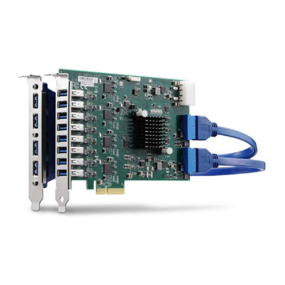
- Page 1 PCIe-U300 Series 4/8/12-ch PCI Express® x4 Gen2 USB3 Vision Top Performing Frame Grabbers User’s Manual Manual Rev.: Revision Date: December 11, 2020 Part No: 50-11268-1010 Leading EDGE COMPUTING...
-
Page 2: Revision History
Leading EDGE COMPUTING Revision History Revision Release Date Description of Change(s) 1.00 2019-10-22 Initial release Add PCIe-U312 version; rename to PCIe-U300 Series; update PCIe-U304/U308 2020-12-11 to "A2" PCB revision (refer to user’s manual Rev. 1.00 for "A1" PCB revision info) Revision History... -
Page 3: Preface
PCIe-U300 Series Preface Copyright © 2019, 2020 ADLINK Technology Inc. This document contains proprietary information protected by copy- right. All rights are reserved. No part of this manual may be repro- duced by any mechanical, electronic, or other means in any form without prior written permission of the manufacturer. - Page 4 Leading EDGE COMPUTING California Proposition 65 Warning WARNING: This product can expose you to chemicals including acrylamide, arsenic, benzene, cadmium, Tris(1,3-dichloro-2-propyl)phosphate (TDCPP), 1,4-Diox- ane, formaldehyde, lead, DEHP, styrene, DINP, BBP, PVC, and vinyl materials, which are known to the State of California to cause cancer, and acrylamide, benzene, cadmium, lead, mercury, phthalates, toluene, DEHP, DIDP, DnHP, DBP, BBP, PVC, and vinyl materials, which are known to the State of California to cause...
-
Page 5: Table Of Contents
PCIe-U300 Series Table of Contents Revision History..............ii Preface ..................iii List of Figures ............... vii List of Tables................ix 1 Introduction ................ 1 Overview................1 Features................2 Applications ................. 3 Specifications............... 4 USB Power ................6 1.5.1 Overcurrent Protection ..........6 1.5.2... - Page 6 Leading EDGE COMPUTING 3 Getting Started ..............23 Unpacking Checklist ............23 Installation................23 Important Safety Instructions..........25 Getting Service ..............27 Table of Contents...
-
Page 7: List Of Figures
Figure 2-5: PCIe-U312 Connector, Jumper and LED Locations ..17 Figure 2-6: PCIe-U312 USB Port Assignment ......... 18 Figure 2-7: 4-pin 12V Power Connector........... 19 Figure 2-8: Card ID Switch............... 20 Figure 2-9: PCIe-U300 Series Status LEDs........21 List of Figures... - Page 8 Leading EDGE COMPUTING This page intentionally left blank. viii List of Figures...
-
Page 9: List Of Tables
Table 2-4: USB 3.0 Type-A Port Pin Assignment ......19 Table 2-5: 4-pin 12V Power Connector Pin Assignment....19 Table 2-6: Card ID Switch Settings..........20 Table 2-7: Card ID Switch Legend..........20 Table 2-8: PCIe-U300 Series Status LED Legend......21 List of Tables... - Page 10 Leading EDGE COMPUTING This page intentionally left blank. List of Tables...
-
Page 11: Introduction
PCIe-U308 - 8 USB ports (shared bandwidth) PCIe-U312 - 12 USB ports (shared bandwidth) The PCIe-U300 Series delivers 5V and up to 1500mA per port for external USB3 Vision® industrial cameras. To ensure industrial- grade high-bandwidth performance for each port, the card uses four independent Fresco FL1100 USB 3.1 Gen 1 Host Controllers... -
Page 12: Features
Leading EDGE COMPUTING 1.2 Features PCI Express x4 Gen2 interface 4 Independent Fresco FL1100 USB 3.1 Gen 1 Host Control- lers Data Transfer Rates: SuperSpeed (5.0 Gbps), High Speed (480.0 Mbps), Full Speed (12.0 Mbps) and Low Speed (1.5 Mbps) 4/8/12 USB 3.0 Type-A connectors 5V, up to 1500mA per port Up to 20/60W power supply from PCIe bus / 4-pin Molex... -
Page 13: Applications
PCIe-U300 Series 1.3 Applications The PCIe-U300 Series is ideally suited for frame grabbing in a wide variety of applications including: Machine Vision Inspection systems Factory Automation Quality Assurance The PCIe-U300 Series Function Library Reference and driver can be downloaded from http://www.adlinktech.com... -
Page 14: Specifications
4-pin Molex Max. 20W USB Power req’d for extension ports Power Connector Delivery PCIe Slot w/ Capacity Max. 30W Max. 60W 4-pin Molex Max. 78W USB Power (at PSE) USB Power USB Power Connector Table 1-1: PCIe-U300 Series Specifications Introduction... -
Page 15: Table 1-1: Pcie-U300 Series Specifications
167.65 mm x 111.15 mm Dimensions (W x L) (6.59" x 4.37") Operating Temperature 0°C to 60°C (32° to 140°F) Humidity 5% to 90% RHNC Storage Temperature -40°C to 85°C (-40°F to 185°F) Safety Compliance CE/FCC, Class A Table 1-1: PCIe-U300 Series Specifications Introduction... -
Page 16: Usb Power
Leading EDGE COMPUTING 1.5 USB Power The PCIe-U300 Series provides a choice of 4, 8 or 12 USB 3.0 ports supporting Type-A USB3.0 connections on the front panel, with 5V at 1500mA per port and extension port with 5V at 900mA per port. -
Page 17: Pcb Layout And Dimensions
PCIe-U300 Series 1.6 PCB Layout and Dimensions All dimensions areshown in mm. NOTE: NOTE: 1.6.1 PCIe-U304 Layout 167, 65 106, 65 Figure 1-1: PCIe-U304 Top View Dimensions Figure 1-2: PCIe-U304 Side View Introduction... -
Page 18: Figure 1-3: Pcie-U304 Bottom View
Leading EDGE COMPUTING Figure 1-3: PCIe-U304 Bottom View Figure 1-4: PCIe-U304 Front and Rear View Introduction... -
Page 19: Pcie-U308 Layout
PCIe-U300 Series 1.6.2 PCIe-U308 Layout 167, 65 106, 65 Figure 1-5: PCIe-U308 Top View Dimensions Figure 1-6: PCIe-U308 Side View Introduction... -
Page 20: Figure 1-7: Pcie-U308 Bottom View
Leading EDGE COMPUTING Figure 1-7: PCIe-U308 Bottom View Figure 1-8: PCIe-U308 Front and Rear View Introduction... -
Page 21: Pcie-U312 Layout
PCIe-U300 Series 1.6.3 PCIe-U312 Layout 167, 65 106, 65 Figure 1-9: PCIe-U312 Top View Dimensions Figure 1-10: PCIe-U312 Side View Introduction... -
Page 22: Figure 1-11: Pcie-U312 Bottom View
Leading EDGE COMPUTING Figure 1-11: PCIe-U312 Bottom View Figure 1-12: PCIe-U312 Front and Rear View Introduction... -
Page 23: Board Interfaces
PCIe-U300 Series Board Interfaces 2.1 PCIe-U304 Interface Layout Figure 2-1: PCIe-U304 Connector, Jumper and LED Locations USB Type-A connectors Card ID Switch (SW1) LED Status Indicators 4-pin 12V Connector Table 2-1: PCIe-U304 Connector, Jumper and LED Legend Board Interfaces... -
Page 24: Figure 2-2: Pcie-U304 Usb Port Assignment
Leading EDGE COMPUTING Port 1 Port 2 Port 3 Port 4 Figure 2-2: PCIe-U304 USB Port Assignment Board Interfaces... -
Page 25: Pcie-U308 Interface Layout
PCIe-U300 Series 2.2 PCIe-U308 Interface Layout Figure 2-3: PCIe-U308 Connector, Jumper and LED Locations USB Type-A connectors Card ID Switch (SW1) Status LEDs 4-pin 12V Connector Table 2-2: PCIe-U308 Connector, Jumper and LED Legend Board Interfaces... -
Page 26: Figure 2-4: Pcie-U308 Usb Port Assignment
Leading EDGE COMPUTING Port 1 Port 2 Port 3 Port 4 Port 5 Port 6 Port 7 Port 8 Figure 2-4: PCIe-U308 USB Port Assignment Board Interfaces... -
Page 27: Pcie-U312 Interface Layout
PCIe-U300 Series 2.3 PCIe-U312 Interface Layout Figure 2-5: PCIe-U312 Connector, Jumper and LED Locations USB Type-A connectors Card ID Switch (SW1) Status LEDs 4-pin 12V connector Internal 20-pin header for USB 3.0 Ports 9-12 Extension Table 2-3: PCIe-U312 Connector, Jumper and LED Legend... -
Page 28: Figure 2-6: Pcie-U312 Usb Port Assignment
Leading EDGE COMPUTING Port 1 Port 9 Port 2 Port 3 Port 10 Port 4 Port 5 Port 11 Port 6 Port 7 Port 12 Port 8 Figure 2-6: PCIe-U312 USB Port Assignment Board Interfaces... -
Page 29: Connector, Jumper And Led Definitions
PCIe-U300 Series 2.4 Connector, Jumper and LED Definitions 2.4.1 USB Ports Signal Signal VBUS SSRX- SSRX+ GND_DRAIN SSTX- SSTX+ Table 2-4: USB 3.0 Type-A Port Pin Assignment 2.4.2 4-pin 12V Power Connector (CN10) Figure 2-7: 4-pin 12V Power Connector Signal... -
Page 30: Card Id Switch (Sw1)
Leading EDGE COMPUTING 2.4.3 Card ID Switch (SW1) D I P Figure 2-8: Card ID Switch Setting Definition 1 (Default) Table 2-6: Card ID Switch Settings The Card ID default setting is at 15 (0x1111). Card ID Table 2-7: Card ID Switch Legend Board Interfaces... -
Page 31: Status Leds
1/3/4/5 Normal (default) Abnormal: PCIe switch upstream function (to PCIe slot) is disabled 2/6/7/8 PCIe x4 Gen2 (default) Blinking Insufficient bandwidth Normal (default) Abnormal: PCIe switch has experienced an unexpected error Table 2-8: PCIe-U300 Series Status LED Legend Board Interfaces... - Page 32 Leading EDGE COMPUTING This page intentionally left blank. Board Interfaces...
-
Page 33: Getting Started
NOTE: NOTE: 3.2 Installation The following describes installation of the PCIe-U300 Series card on a PCI Express bus. 1. Remove the computer cover according to the computer manual. A vacant PCI Express slot is required for installation of the card;... - Page 34 NOTE: NOTE: PCIe-U300 Series cards may not fit some consumer PC cases with non-standard PCIe slots. It is not recommended to install PCIe-U300 Series cards into a PC with a PCIe slot width less NOTE: NOTE: than 13.25mm (0.512"). Getting Started...
-
Page 35: Important Safety Instructions
PCIe-U300 Series Important Safety Instructions For user safety, please read and follow all instructions, Warnings, Cautions, and Notes marked in this manual and on the associated device before handling/operating the device, to avoid injury or damage. S'il vous plaît prêter attention stricte à tous les avertissements et mises en garde figurant sur l'appareil , pour éviter des blessures... - Page 36 Leading EDGE COMPUTING A Lithium-type battery may be provided for uninterrupted backup or emergency power. Risk of explosion if battery is replaced with one of an incorrect type; please dispose of used batteries appropriately. Risque d’explosion si la pile est remplacée par une autre de CAUTION: type incorrect.
-
Page 37: Getting Service
San Jose, CA 95138, USA Tel: +1-408-360-0200 Toll Free: +1-800-966-5200 (USA only) Fax: +1-408-360-0222 Email: info@adlinktech.com ADLINK Technology (China) Co., Ltd. 300 Fang Chun Rd., Zhangjiang Hi-Tech Park Pudong New Area, Shanghai, 201203 China Tel: +86-21-5132-8988 Fax: +86-21-5132-3588 Email: market@adlinktech.com ADLINK Technology GmbH Hans-Thoma-Straße 11...
Need help?
Do you have a question about the PCIe-U300 Series and is the answer not in the manual?
Questions and answers