Table of Contents
Advertisement
Quick Links
Advertisement
Table of Contents

Related Manuals for ADLINK Technology NuDAQ PCI-7258


Summary of Contents for ADLINK Technology NuDAQ PCI-7258
- Page 1 NuDAQ PCI-7258 PhotoMos Relay Cards User’s Guide Recycled Paper...
- Page 3 Trademarks NuDAQ is registered trademarks of ADLINK Technology Inc. Other product names mentioned herein are used for identification purposes only and may be trademarks and/or registered trademarks of their respective companies.
- Page 4 Customer Satisfaction is the most important priority for ADLINK Tech Inc. If you need any help or service, please contact us. ADLINK Technology Inc. Web Site http://www.adlinktech.com Sales & Service Service@adlinktech.com NuDAQ + USBDAQ nudaq@adlinktech.com Automation automation@adlinktech.com Technical Support NuIPC nuipc@adlinktech.com...
-
Page 5: Table Of Contents
Table of Contents Tables and Figures..............iii How to Use This Guide............iv Introduction ................1 Features ................. 2 Applications ..............2 Specifications ..............2 Software Support ............4 1.4.1 Programming Library..............4 1.4.2 PCIS-LVIEW: LabVIEW® Driver..........4 1.4.3 PCIS-VEE: VEE Driver............5 1.4.4 PCIS-OCX: ActiveX Controls..........5 1.4.5 PCIS-DDE: DDE Server and InTouch .......5... - Page 6 Operation Theory ..............20 PhotoMos Relay Output ..........20 Isolated Digital Input ............22 Interrupt Architecture............. 22 C/C++ DOS Libraries ............23 Programming Guide ............23 5.1.1 Naming Convention..............23 5.1.2 Data Types................24 _7258 Initial ..............25 _7258_DO..............26 _7258_DO_Read_Back..........26 _7258_DI ..............
- Page 7 Data Types and Range ..............24 Figures Figure 1: PCI-7258 PCB Layout..............9 Figure 2: Board ID Dipswitch...............11 Figure 3: Pin Assignment of PCI-7258 CN1..........12 Figure 4: PhotoMos relay schematic............20 Figure 5: PhotoMos relay wiring diagram ..........21 Figure 6: Protection circuit for an Inductive load........21 Figure 7: Photo-Coupler................22...
-
Page 8: How To Use This Guide
How to Use This Guide This manual is intended to assist users to configure the PCI-7258 PhotoMos Relay Card. It is divided into 5 chapters. Chapter 1, “Introduction”, gives an overview of the product features, applications, and specifications. Chapter 2, “Getting Started”, describes how to install the PCI-7258. -
Page 9: Introduction
Introduction The PCI-7258 PhotoMos relay card is a basic Digital I/O card for PCI bus computers used in industrial applications. This PCI-7258 provides 32 PhotoMos relay actuators and 2 opto-isolated digital inputs. All relays are of Form A type and is very suited for constant ON/OFF control devices. -
Page 10: Features
Features The PCI-7258 PhotoMos relay actuator and D/I Card provides the following advanced features: 32-bit PCI-Bus, Plug and Play 32 PhotoMos relay actuator outputs 2 opto-isolated digital inputs On-board relay driving circuits Digital input channel 0 & 1 interrupt Board ID... - Page 11 Input Voltage: Up-to 24 V or 24V Logic Low: 0~2V Logic High 5~24V Input impedance: 2.4 K / 0.5W Isolated voltage: 2,500 V channel-to-system Relay Output Output channels: 32 Relay type: 32 SPST (Form A) Load voltage (peak AC): 350V Continuous load current (peak AC): 0.12A Peak load current: 0.3A I/O isolation voltage: 1,500 V AC...
-
Page 12: Software Support
Software Support ADLINK provides versatile software drivers and packages for users’ different approach to building a system. ADLINK not only provides programming libraries such as DLL for most Windows based systems, but also provide ® drivers for other software packages such as LabVIEW , VEE , InTouch InControl... -
Page 13: Pcis-Vee: Vee Driver
1.4.3 PCIS-VEE: VEE Driver The PCIS-VEE includes user objects, which are used to interface with the VEE software package. PCIS-VEE supports Windows 95/98/NT. The VEE drivers are shipped free with the board. You can install and use them without a license. For more information about PCIS-VEE, please refer to the user’s guide in the CD. -
Page 14: Pcis-Icl: Incontrol
1.4.7 PCIS-ICL: InControl Driver PCIS-ICL is the InControl driver, which supports Windows NT. The PCIS-ICL is included in the ADLINK CD. It is not free and requires a license. Please contact ADLINK dealers or ADLINK to purchase the license. 1.4.8 PCIS-OPC: OPC Server PCIS-OPC is an OPC server, which can be used to link with other OPC clients. -
Page 15: Getting Started
Getting Started This chapter describes how to install and setup the PCI-7258. The contents in the package and unpacking information that you should be aware of are outlined first. What you have In addition to the User’s Manual, the package should include the following... -
Page 16: Unpacking
Unpacking The card contains electro-static sensitive components that can be easily be damaged by static electricity. Therefore, the card should be handled on a grounded anti-static mat. The operator should be wearing an anti-static wristband, grounded at the same point as the anti-static mat. Inspect the card module carton for obvious damages. -
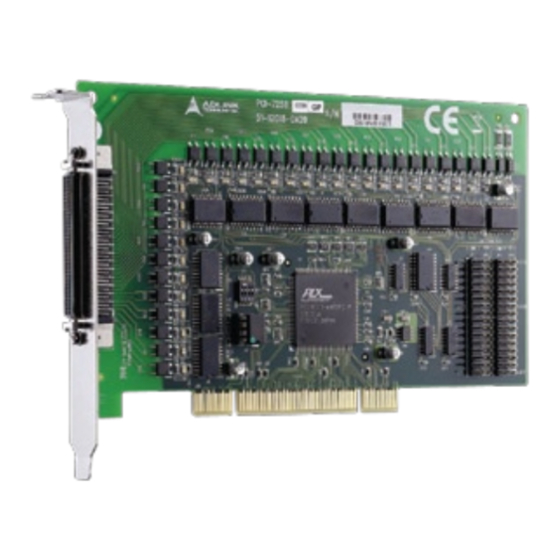
Page 17: Pcb Layout
PCB Layout The location of the connectors and switches on the PCI-7258 are shown in figure 1 below. Descriptions are o utline in the proceeding sections. Figure 1: PCI-7258 PCB Layout Getting Started 9... - Page 18 Figure 2: PCI-7258 External LED connector The PCI-7258 card is designed with 32 LEDs, each indicating the operation status of the 32 relays. In addition, there are also 32 external LED connectors available for users’ to use as so pleases. Utilizing the external LEDs connecting to JP1 or JP2, users can have a visual status of each relay displayed on a chassis, panel or on any apparatus.
-
Page 19: Board Id
Board ID When two or more data acquisition cards are installed in a system, it can be tedious trying to identify a specific card. For easier identification, the PCI- 7258 implemented a Board ID function. By setting the Dipswitch located at S1, users can assign an ID address to a specific card and access the card through software programming. -
Page 20: Connector Pin Assignments
Connector Pin Assignments The PCI-7258 card is equipped with a 68-pin SCSI connector (CN1). Figure 3 defines the pin assignment for the connector. NO18 COM1 COM18 NO19 COM2 COM19 NO20 COM3 COM20 NO21 COM4 COM21 NO22 COM5 COM22 NO23 COM6... -
Page 21: Termination Board Connection
The available termination board for the 68-pin SCSI connector is the DIN- 68S/1S. The DIN-68S/1S is a general-purpose 68-pin screw terminal with a DIN socket. It is also equipped with a 68-pin SCSI cable that allows for easy installation of the PCI-7258. Getting Started 13... -
Page 23: Registers
However, we suggest users to have an understanding of the PCI interface before starting any low-level programming. I/O Address Map The PCI-7258 registers are all 16-bits long. Users can access these registers by 16-bit I/O instructions only. The controls for the relays and status of the isolated inputs are by means of accessing these registers. -
Page 24: Relay Output Control Register
Relay Output Control Register There are 32 PhotoMos relays on the PCI-7258; each bit of the register corresponds to a relay channel. Writing “1” to the register will cause the relay to close and “0” will cause it to open. -
Page 25: Relay Output Read Back Register
Relay Output Read Back Register The status of the PhotoMos relay can be read back from the readback register. If the relay is in the close position, the corresponding bit value is ‘1’. If the relay is open, then the bit value is ‘0’. Address: BASE + 0x00 Attribute: Read RBK8... -
Page 26: Isolated Digital Input Register
Isolated Digital Input Register There are 2 isolated input channels on PCI-7258 card. The status of the 2 channels can be read from the isolated input register. Each bit corresponds to each channel. A “1” means the input logic is high and “0” means the input logic is low. -
Page 27: Handling Pci Controller Registers
PCI bus. When users want to develop their own interrupt function driver, both interrupt registers in the PCI- 9030 and in PCI-7258 have to work together. For more information about the interrupt control register in the PCI-9030, refer to the PCI-9030 data book. -
Page 28: Operation Theory
Operation Theory PhotoMos Relay Output The PhotoMos relay has LED inputs and MOSFET outputs that provide input- output isolation. When a signal current flows into the LED input pin, the emitted light from the LED is detected by the photoelectric element (solar cell), which is mounted opposite to the LED. - Page 29 Furthermore, dithering problems is eliminated. The PCI-7258 is equipped with 32 PhotoMos relays, which are all form A type. The load voltage can either be AC or DC. The basic wiring diagram is shown in figure 5 below.
-
Page 30: Isolated Digital Input
0 to 24V. Interrupt Architecture PCI-7258 has a powerful dual interrupt routing scheme and t h e interrupt sources are on the digital input channels 0 and 1. Using these interrupts will make handling complicated digital information much easier and relief your computer from the heavy burden of dealing with digital input data. -
Page 31: C/C++ Dos Libraries
The functions of the NuDAQ PCI or NuIPC CompactPCI card software drivers uses full-names to represent the functions' real meaning. The naming convention rules are: _{hardware_model}_{action_name}. e.g. _7258_Initial() . All functions in the PCI-7258 drivers are with 7258 as {hardware_model}. C/C++ Libraries 23... -
Page 32: Data Types
Data Types We have defined some data types in the ACL_PCI.h header file. These data types are used by the NuDAQ Cards’ library. We suggest you use these data types in your application programs. The following table shows the data type names and their range. -
Page 33: 7258 Initial
@ Description The PCI-7258 cards are initialized according to the card number. Because the PCI-7258 is designed with the PCI bus architecture and meets the plug and play specifications, the IRQ and base_address (pass-through address) are assigned by system BIOS directly. Every PCI-7258 card has to be initialized by this function before using any other functions. -
Page 34: 7258_Do_Read_Back
_7258_DO @ Description @ Syntax U16 _7258_DO (U16 boardID, U16 Group, U16 doData) @ Argument boardID: Board ID for the specific board. Group: group 0 represents DO channel 1~16, group 1 represents DO channel 17~32. doData: value which will be written to digital output port. @ Return Code ERR_NoError, ERR_BoardNoInit, ERR_InvalidDOChannel _7258_DO_Read_Back... -
Page 35: 5.6 _7258_Int_Control
ERR_NoError, ERR_BoardNoInit 5.6 _7258_INT_Control @ Description This function is used to control the interrupt source of the PCI-7258. The interrupt source can be the digital input of channel 0, 1 or both. @ Syntax U16 _7258_INT_Control (U16 boardID, U16 int1Flag, U16 int2Flag) -
Page 36: 7258_Clr_Irq
_7258_CLR_IRQ @ Description This function is used to clear the interrupt request. @ Syntax U16 _7258_CLR_IRQ (U16 boardID) @ Argument boardID: Board ID for the specific board. @ Return Code ERR_NoError, ERR_BoardNoInit 5.10 _7258_GET_IRQ_Status @ Description This function is used to obtain the interrupt status. @ Syntax U16 _7258_GET_IRQ_Status (U16 boardID, U16 *int1Status, U16 *int2Status) -
Page 37: Warranty Policy
Warranty Policy Thank you for choosing ADLINK. To understand your rights and enjoy all the after-sales services we offer, please read the following carefully. Before using ADLINK’s products, please read the user manual and follow the instructions carefully. When sending in damaged products for repair, please attach an RMA application form. - Page 38 . Damaged products with RMA forms attached receive priority. For further questions, please contact our FAE staff. ADLINK: service@adlinktech.com Test & Measurement Product Segment: NuDAQ@adlinktech.com Automation Product Segment: Automation@adlinktech.com Computer & Communication Product Segment: NuPRO@adlinktech.com; NuIPC@adlinktech.com 30 Warranty Policy...
Need help?
Do you have a question about the NuDAQ PCI-7258 and is the answer not in the manual?
Questions and answers