
Subscribe to Our Youtube Channel
Related Manuals for ADLINK Technology PCIe-GIE62


Summary of Contents for ADLINK Technology PCIe-GIE62
- Page 1 PCIe-GIE62 2-CH Gigabit Ethernet Vision (GigE Vision) Interface Card User’s Manual Manual Rev. 2.00 Revision Date: July 31, 2007 Part No: 51-18015-0A10 Advance Technologies; Automate the World.
- Page 2 Copyright 2008 ADLINK TECHNOLOGY INC. All Rights Reserved. The information in this document is subject to change without prior notice in order to improve reliability, design, and function and does not represent a commitment on the part of the manufacturer.
- Page 3 Getting Service from ADLINK Customer Satisfaction is top priority for ADLINK Technology Inc. Please contact us should you require any service or assistance. ADLINK TECHNOLOGY INC. Web Site: http://www.adlinktech.com Sales & Service: Service@adlinktech.com TEL: +886-2-82265877 FAX: +886-2-82265717 Address: 9F, No. 166, Jian Yi Road, Chungho City,...
-
Page 5: Table Of Contents
Features................2 Applications ................. 2 2 Hardware Reference............3 PCIe-GIE62 ................. 3 PCIe-GIE62 Specification ..........3 PCIe-GIE62 Connectors & Pin Definitions ...... 4 3 Installation Guide ............. 13 Hardware Installation ............13 Driver Installation ............... 14 4 Function Library ............... 21 Function List .............. -
Page 6: List Of Tables
List of Tables Table 2-1: J2 RJ-45: LAN 1 Port ..........5 Table 2-2: J3 RJ-45: LAN 2 Port ..........5 Table 2-3: LED1: LAN 1 status LED .......... 6 Table 2-4: LED2: LAN 2 status LED .......... 6 Table 2-5: SW1: Card ID Select ..........7 Table 2-6: Card ID Select Table .......... -
Page 7: List Of Figures
List of Figures Figure 2-1: PCIe-GIE62 Layout ..........4 List of Figures... -
Page 9: Introduction
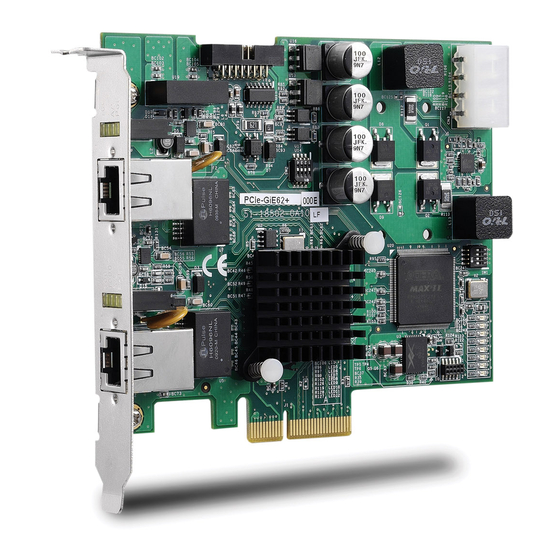
Introduction The ADLINK PCIe-GIE62 is a PCI Express x4 lane, Gigabit Ether- net (GbE) network interface card (NIC), which supports 2 indepen- dent Gigabit Ethernet ports for multiple GigE Vision device connections with data transfer rates up to 1000 Mb/s, like most of the GigE Vision cameras. -
Page 10: Features
1.1 Features Supports two independent GbE ports Supports jumbo frames (9 KByte) PCI Express x4 compliant Provides Industrial screw lock connector 2 isolation digital inputs/outputs 2 isolation TTL level programmable trigger output pulses Supports windows XP/XP embedded/Vista 1.2 Applications Machine Vision Inspection System Scientific Research Instrumentation Medical Research Instrumentation Introduction... -
Page 11: Hardware Reference
W x L: 129.5 x 111.15 mm Operating Environment Temperature: 0 to 55°C Humidity: 5 to 90% RHNC Storage Environment Temperature: 0 to 85°C Humidity: 0 to 95% RHNC Power Requirements PCIe-GIE62: +12 V max @ 0.2 A, +3.3 V max @ 1.5 A Hardware Reference... -
Page 12: Pcie-Gie62 Connectors & Pin Definitions
2.1.2 PCIe-GIE62 Connectors & Pin Definitions Figure 2-1: PCIe-GIE62 Layout Hardware Reference... -
Page 13: Table 2-1: J2 Rj-45: Lan 1 Port
J2, J3 RJ-45 Ethernet Port J2 RJ-45: LAN 1 Port Pin Signal Pin Signal MDI0+ MDI2- MDI0- MDI1- MDI1+ MDI3+ MDI2+ MDI3- Table 2-1: J2 RJ-45: LAN 1 Port J3 RJ-45 : LAN 2 port Pin Signal Pin Signal MDI0+ MDI2- MDI0- MDI1-... -
Page 14: Table 2-3: Led1: Lan 1 Status Led
LED1: LAN 1 status LED LED Color Color Function Table 1: Orange Table 2: 1000Mbps Bi color Green 100Mbps (Speed status) 10Mbps Link Green Link off (Link status) Blinking Data transfer in progress LED1: LAN 1 status LED Table 2-3: LED2 : LAN 2 status LED LED Color Color... -
Page 15: Table 2-5: Sw1: Card Id Select
SW1: Card ID Select Card ID Max. support 4 cards Pin no Signal Name Default Board ID Select 0 Board ID Select 1 Non use Non use Table 2-5: SW1: Card ID Select Card ID Board ID Select 0 Board ID Select 1 Table 2-6: Card ID Select Table Hardware Reference... -
Page 16: Table 2-7: Cn3: Gpio & Trigger
CN3: GPIO & Trigger PIN NAME TYPE PIN PIN NAME TYPE In01 ComI01 In02 ComI02 Out01 ComO01 Out02 ComO02 TrgIn1 10 TrgComI01 TrgIn2 12 TrgComI02 TrgOut1 TrgOut2 Frame Ground Table 2-7: CN3: GPIO & Trigger Digital Input Circuit Digital Output Circuit Hardware Reference... - Page 17 Trigger Input Circuit Trigger Output Circuit Hardware Reference...
- Page 18 Function Electronic Specification Isolated Digital Input Photo Coupled Input x 2 ch Input voltage range 0 to 25V Low level 0 to 0.5V High Level 2 to 25V Isolated Digital Output Photo Coupled Output x 2 ch Load voltage range 3 to 24V Output sink current 80mA (Max)
- Page 19 Trigger Control Timing Chart Trigger Busy Control Hardware Reference...
-
Page 20: Table 2-8: Extension Cable Connector: D-Sub 15 Pin Female
Trigger Enable Control Extension Cable Connector: D-sub 15 Pin Female PIN NAME TYPE PIN PIN NAME TYPE In01 ComI01 In02 ComI02 Out01 ComO01 Out02 ComO02 TrgIn1 13 TrgComI01 TrgIn2 14 TrgComI02 TrgOut1 TrgOut2 Frame Ground Table 2-8: Extension Cable Connector: D-sub 15 Pin Female Hardware Reference... -
Page 21: Installation Guide
5. Press the board firmly, but carefully into the connector. 6. Anchor the board by replacing the screw. 7. Connect device via a Gigabit Ethernet connector. 8. Turn on the computer. Note: The PCIe-GiE62 can be installed in a PCI express x4, x8, and x16 slot. Installation Guide... -
Page 22: Driver Installation
3.2 Driver Installation 1. Double Click PRO2KXP.exe (for 2K/XP) or PRO- VISTA.exe (for Vista) to start driver installation of Intel network chipsets according to your operating system. Installation Guide... - Page 23 2. Click “Next” to continue driver installation. Installation Guide...
- Page 24 3. Click “Install” to start installing. Installation Guide...
- Page 25 4. Click “Finish” to end driver installation. Installation Guide...
- Page 26 5. Go to the “Device Manager” and check “Network adapt- ers”. You should see the following items: Intel(R) PRO/100 S Server Adapter Intel(R) PRO/1000 EB Network Connection with I/O Acceleration Intel(R) PRO/1000 EB Network Connection with I/O Acceleration #2 Intel(R) PRO/1000 PT Dual Port Server Adapter Intel(R) PRO/1000 PT Dual Port Server Adapter #2 Installation Guide...
- Page 27 6. Double Click GiE62_SetupDisk_1001.exe to start driver installation of ADLINK GiE62. 7. Click “Next” to continue driver installation. Installation Guide...
- Page 28 8. Click “Install” to start installing. 9. Click “Finish” to end driver installation. Installation Guide...
-
Page 29: Function Library
Function Library 4.1 Function List Function name Description System Functions Load the driver of GiE62 card. You must call this GiE62_Initialize function before any other functions GiE62_GetTotalDeviceNum Get the number of GiE62 cards in your system Get the CardID(s) of each GiE62 cards in your GiE62_GetTotalDeviceID system GiE62_OpenDevice... -
Page 30: Functions
4.2 Functions 4.2.1 GiE62_Initialize Description Load the driver of GiE62 card. You must call this function before any other functions. Syntax int GiE62_Initialize(); Function Library... -
Page 31: Gie62_Gettotaldevicenum
4.2.2 GiE62_GetTotalDeviceNum Description Get the number of GiE62 cards in your system. Syntax int GiE62_GetTotalDeviceNum(); Function Library... -
Page 32: Gie62_Gettotaldeviceid
4.2.3 GiE62_GetTotalDeviceID Description Get the CardID(s) of each GiE62 cards in your system. Syntax int GiE62_GetTotalDeviceID(int *DeviceID); Parameters DeviceID [out] Pointer to a 32-bit integer array which stores the read out CardID(s). Function Library... -
Page 33: Gie62_Opendevice
4.2.4 GiE62_OpenDevice Description Open GiE62 card to the default status. Syntax int GiE62_OpenDevice(int CardID); Parameters CardID [in] Card ID of GiE62. The card ID could be 0, 1, 2 and 3. It is defined by the DIP switch on GiE62. Function Library... -
Page 34: Gie62_Resetdevice
4.2.5 GiE62_ResetDevice Description Reset GiE62 card and set it to the default state. Syntax int GiE62_ResetDevice(int CardID); Parameters CardID [in] Card ID of GiE62. The card ID could be 0, 1, 2 and 3. It is defined by the DIP switch on GiE62. Function Library... -
Page 35: Gie62_Getfirmwareversion
4.2.6 GiE62_GetFirmwareVersion Description Get the firmware version of GiE62 card. Syntax int GiE62_GetFirmwareVersion(int CardID, char *FirmwareVersion, int StringSize); Parameters CardID [in] Card ID of GiE62. The card ID could be 0, 1, 2 and 3. It is defined by the DIP switch on GiE62. port [out] Pointer to a character array which stores the read out firmware version. -
Page 36: Gie62_Setdostatus
4.2.7 GiE62_SetDOStatus Description Set general purpose digital output status. Syntax int GiE62_SetDOStatus(int CardID, int port, int status); Parameters CardID [in] Card ID of GiE62. The card ID could be 0, 1, 2 and 3. It is defined by the DIP switch on GiE62. port [in] Port number of GiE62. -
Page 37: Gie62_Getdistatus
4.2.8 GiE62_GetDIStatus Description Get general purpose digital input status. Syntax int GiE62_GetDIStatus(int CardID, int port, int *status); Parameters CardID [in] Card ID of GiE62. The card ID could be 0, 1, 2 and 3. It is defined by the DIP switch on GiE62. port [in] Port number of GiE62. -
Page 38: Gie62_Settriggerdelaytime
4.2.9 GiE62_SetTriggerDelayTime Description Set the delay time of output triggers. Syntax int GiE62_SetTriggerDelayTime(int CardID, int port, int DelayTime); Parameters CardID [in] Card ID of GiE62. The card ID could be 0, 1, 2 and 3. It is defined by the DIP switch on GiE62. port [in] Port number of GiE62. -
Page 39: Gie62_Settriggeroutwidth
4.2.10 GiE62_SetTriggerOutWidth Description Set the width of output triggers. Syntax int GiE62_SetTriggerOutWidth(int CardID, int port, int width); Parameters CardID [in] Card ID of GiE62. The card ID could be 0, 1, 2 and 3. It is defined by the DIP switch on GiE62. port [in] Port number of GiE62. -
Page 40: Gie62_Settriggeroutpolarity
4.2.11 GiE62_SetTriggerOutPolarity Description Set the output polarity of output triggers. Syntax int GiE62_SetTriggerOutPolarity(int CardID, int port, int OutPolarity); Parameters CardID [in] Card ID of GiE62. The card ID could be 0, 1, 2 and 3. It is defined by the DIP switch on GiE62. port [in] Port number of GiE62. -
Page 41: Gie62_Settriggerinpolarity
4.2.12 GiE62_SetTriggerInPolarity Description Set the input polarity of output triggers. Syntax int GiE62_SetTriggerInPolarity(int CardID, int port, int InPolarity); Parameters CardID [in] Card ID of GiE62. The card ID could be 0, 1, 2 and 3. It is defined by the DIP switch on GiE62. port [in] Port number of GiE62. -
Page 42: Gie62_Gettriggerdelaytime
4.2.13 GiE62_GetTriggerDelayTime Description Get the delay time of output triggers. Syntax int GiE62_GetTriggerDelayTime(int CardID, int port, int *DelayTime); Parameters CardID [in] Card ID of GiE62. The card ID could be 0, 1, 2 and 3. It is defined by the DIP switch on GiE62. port [in] Port number of GiE62. -
Page 43: Gie62_Gettriggeroutwidth
4.2.14 GiE62_GetTriggerOutWidth Description Obtain the width of output triggers. Syntax int GiE62_GetTriggerOutWidth(int CardID, int port, int *width); Parameters CardID [in] Card ID of GiE62. The card ID could be 0, 1, 2 and 3. It is defined by the DIP switch on GiE62. port [in] Port number of GiE62. -
Page 44: Gie62_Gettriggeroutpolarity
4.2.15 GiE62_GetTriggerOutPolarity Description Get the output polarity of output triggers. Syntax int GiE62_GetTriggerOutPolarity(int CardID, int port, int *OutPolarity); Parameters CardID [in] Card ID of GiE62. The card ID could be 0, 1, 2 and 3. It is defined by the DIP switch on GiE62. port [in] Port number of GiE62. -
Page 45: Gie62_Gettriggerinpolarity
4.2.16 GiE62_GetTriggerInPolarity Description Get the input polarity of output triggers. Syntax int GiE62_GetTriggerInPolarity(int CardID, int port, int *InPolarity); Parameters CardID [in] Card ID of GiE62. The card ID could be 0, 1, 2 and 3. It is defined by the DIP switch on GiE62. port [in] Port number of GiE62. -
Page 46: Error Codes
4.3 Error Codes Error Code Meaning ERROR_NoError ERROR_Invalid_CardID ERROR_Invalid_PortNo ERROR_DeviceNotOpened ERROR_DeviceAlreadyOpened ERROR_ParameterExceedLimit ERROR_DeviceCannotAccess Table 4-1: Error Codes Function Library...
Need help?
Do you have a question about the PCIe-GIE62 and is the answer not in the manual?
Questions and answers