Table of Contents
Advertisement
Quick Links
Advertisement
Table of Contents

Related Manuals for Four winns V Series


Summary of Contents for Four winns V Series
-
Page 3: Table Of Contents
Table of Contents PREFACE .................................10 SAFETY MESSAGES ............................11 OPERATION ..............................17 A - 1 GENERAL .............................17 A - 2 COMPONENT SYSTEMS ......................17 A - 3 SAFETY EQUIPMENT ........................17 A - 4 PASSENGER SAFETY .........................17 A - 5 RULES OF THE ROAD .........................17 A - 6 LIGHTNING ...........................17 A - 7... -
Page 4: Table Of Contents Owner's Manual Page
E. Symp toms ..........................31 F. Treatment (Evaluate, Ventilate, Evacuate, Investigate, Take Corrective Action) ......32 G. Inspection ..........................32 H. Operation ..........................32 I. Boathouses, Sea Walls and Confined Spaces ..............32 J. The Effect of Boats Moored Along Side ...................33 K. Backdrafting (Station Wagon Effect) ..................33 L. -
Page 5: Table Of Contents Owner's Manual Page
WARRANTY AND SERVICE .......................... 47 D - 1 FOUR WINNS WARRANTY POLICY ..................47 D - 2 DECK/HULL STRUCTURE WARRANTY ..................47 D - 3 WARRANTY REGISTRATION ....................47 D - 4 TRANSFER OF WARRANTY ..................... 47 D - 5 PRE-OWNED UNIT REGISTRATION .................. -
Page 6: Table Of Contents Owner's Manual Page
L. Emergency Stop Switch ......................65 M. Alarm Systems ........................66 N. Navigational Equipment ......................66 E - 9 INSTRUMENT MAINTENANCE ....................68 CONTROL SYSTEMS ............................ 69 F - 1 GENERAL ........................... 69 F - 2 CONTROL OPERATION ......................69 A. General ..........................69 B. - Page 7 H - 11 GENERATOR ..........................97 H - 12 ELECTRICAL SYSTEM MAINTENANCE ................... 99 A. Battery Maintenance ......................99 B. Electrical Wiring Maintenance .................... 100 H - 13 STRAY CURRENT CORROSION ..................... 100 A. General ..........................100 B. Galvanic Corrosion ......................100 C.
-
Page 8: Table Of Contents Owner's Manual Page
F. Dockside Waste Pump Out ....................129 J - 7 SYSTEM MAINTENANCE ......................129 A. Clean Vents and Screens ....................130 B. Winterizing the Water System ..................... 130 C. Winterizing the Waste System .................... 131 VENTILATION AND DRAINAGE SYSTEMS ....................132 K - 1 ENGINE COMPARTMENT VENTILATION ................ -
Page 9: Table Of Contents Owner's Manual Page
M - 17 HARD TOP ..........................147 M - 18 ENGINE HATCH WITH ELECTRIC LIFT ................... 148 M - 19 FLAG POLE AND HOLDER ...................... 149 UPHOLSTERY ...............................150 N - 1 INTERIOR FURNISHINGS ......................150 A. Couch ...........................150 B. V-berth or Forward Cabin ....................150 C. -
Page 10: Table Of Contents Owner's Manual Page
P - 5 FIBERGLASS REPAIRS ......................172 A. Scratches ..........................172 B. Gouges & Cracks ........................173 C. Osmotic Blistering ........................173 P - 6 ANTI-FOULING PAINT ........................174 P - 7 HULL SUPPORT .........................174 WOODWORK AND COMPOSITES ........................176 Q - 1 HIGH-PRESSURE LAMINATE CARE ..................176 Q - 2 REAL WOOD TRIM ........................176 Q - 3... -
Page 11: Table Of Contents Owner's Manual Page
C. Capsizing ..........................192 D. Man Overboard ........................192 E. Collision ..........................193 F. Fire ............................193 G. Medical Emergency .......................193 H. Propulsion Failure .........................193 Control Failure ........................194 J. Steering Failure ........................194 K. Additional Underway Information ...................195 S - 11 RETURNING TO SHORE ......................195 A. -
Page 12: Preface
It has been written for the beginning boater but experienced boaters will find helpful information as well. Be sure to read the contents thoroughly. This manual will acquaint you with the use and maintenance of your new Four Winns boat. This manual also pro vides special information critical to the safety of the passengers, and longevity of the equipment. The infor- mation on the following page lists the graphics used to increase the visibility of these important messages. -
Page 13: Safety Messages
Safety Messages The popularity of boating and other water sports has grown tremendously in the past few years. Because of this, safety is an important issue for everyone who shares our waterways. Remember that along with the freedom and exhilaration of boating comes the responsibility that you have for the safety of your passengers and the other boaters who share the water with you. Throughout this manual, specific precautions and symbols identify safety-related information. - Page 14 We’d also like to remind you to be kind to our environment while you’re boating. Don’t throw garbage and other refuse overboard. Do your best to keep harmful compounds like gasoline, oil and antifreeze out of the water. Please see the notifications below: DISCHARGE OF OIL PROHIBITED THE FEDERAL WATER POLLUTION CONTROL ACT PROHIBITS THE DISCHARGE OF OIL OR OILY WASTE INTO OR UPON THE NAVIGABLE WATERS OF THE UNITED STATES, OR THE WATERS OF THE CONTIGUOUS ZONE, OR WHICH MAY EFFECT NATURAL RESOURCES...
- Page 15 Many of these stickers and labels are not required by the US Coast Guard but are important to ensure the safe operation of your Four Winns boat. In addition, the Hull Identifica t ion Number plate is permanently attached below the ®...
- Page 16 NMMA CERTIFICATION LABEL, YACHT CERTIFICATION PLATE & WARNING LABELS NMMA Yacht Certification Plate Replaces NMMA Capacity Label on Certain V series Note: The NMMA Yacht Certification rating (indicated by a yacht certification plate) places the responsibility NMMA Capacity Label on the captain to make the determination as to the See Actual Capacity Plate Affixed to Boat for Actual Capacities.
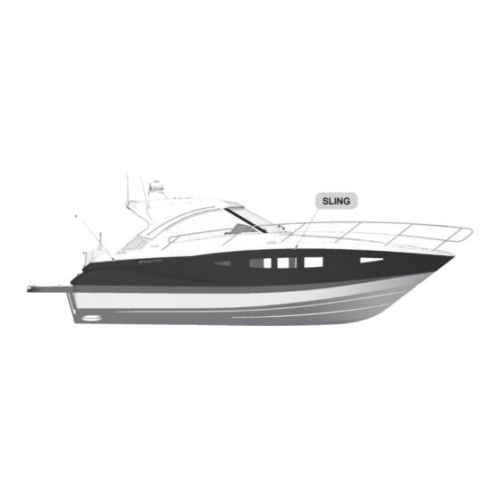
- Page 17 Ensure slings are in proper location as indicated by the sling label location. Failure to do so may result in permanent hull structure damage and will invalidate the hull structure warranty. SLING SLING Figure 2: Sling Locations - Reference Only (Locations will vary depending upon the model) Carbon Monoxide - Cabin Doors Warning Label No Ventilation - Do Not Store Fuel Warning Label...
- Page 18 Gasoline Vapor-Blower Warning Label Rotating Propeller - Helm Warning Label Rotating Propeller - Ladder Warning Label Leaking Fuel Warning Label CO-Cabin Warning Label Ski Tow Warning Label CO-Helm Warning Label Transom/Side Door Warning Label CO Swim Platform and Lounging Area Warning Label Preface Owner’s Manual Page 16...
-
Page 19: Operation
SAFETY EQUIPMENT ed. Books on this subject are also available from local libraries. Besides the equipment installed on the boat by Four Winns certain other equipment is re quired for A - 6 LIGHTNING passenger safety. A booklet listing the Federal equipment requirements is included in the owner’s... -
Page 20: Drugs And Alcohol
1. Visibly check the engine to be sure there are no intoxicat ed person to take the helm. apparent water or oil leaks. Have fun in your Four Winns boat, but also have ® 2. Check the displays . Make sure the oil pres sure, the good sense to be mentally alert and physically water temperature, voltmeter, etc. -
Page 21: Engine Operational Procedures
A - 9 ENGINE OPERATION AL PROCE DURES 6. Lower the vertical outdrive units (if applicable) mak- ing sure the water intakes are under the water. NOTICE B. Cold / Warm Engine Start - EFI & Diesel Consult engine operator’s manual for specific procedure for your particular 1. -
Page 22: Starting Procedures For Diesel Engines With Volvo Penta Electronic Vessel Control (Evc)
idle detent position, press the neutral button “N” NOTICE in and hold it down while moving the control lever When starting engine for the first time after forward to the forward shift position. Release the off-season storage, always idle engine for ten neutral button. The green indicator begins to flash minutes to allow the water pump to prime. indicating the shift function has been disengaged. -
Page 23: Shifting And Control Speed
10. As soon as engine starts, release key to the ON or RUN position. NOTICE Allow the engine to idle for the first ten seconds. Monitor all instruments and displays to ensure normal readings are shown. Check that no alarms are displayed and that no warning lights are flashing. -
Page 24: Stopping Engine - Efi & Diesel
4. To go from FORWARD to REVERSE, or E. Stopping Engine - EFI & Diesel REVERSE to FORWARD; always pause at NEUTRAL and allow engine speed to fall below 1. Move shifter/throttle lever(s) to the NEUTRAL 1500 RPM. position. 2. Turn ignition key to the OFF position. NOTICE On certain models, if you attempt to shift gear at an excessive engine speed, a safety function... -
Page 25: After Stopping Engine(S)
Because of this, Four Winns strongly suggests that boater as well as the experienced boater alike. these activities be left to those who have the equip- Operation - Section A Owner’s Manual Page 23... -
Page 26: Boating Manuals Or Literature
The Canadian Power and Sail Squadron offers For more information contact your local US Coast seamanship courses. Information may be obtained Guard Unit or call the Coast Guard info line at 1 800 by visiting their website at www.cps-ecp.ca/. 368-5647, or visit the US Power Squadron website at www.usps.org. -
Page 27: Accident Reporting
A - 13 ACCIDENT REPORTING A - 16 MARPOL TREATY Boats 26 feet or longer must display a sign stating the The operator of the boat is responsible for filing a disposal regulations of the Federal Water Pollution report with the appropriate authorities. In general, Control Act. The US Coast Guard has issued these reports are necessary for accidents involving loss of regulations to implement Annex V of the International life, injury, or damage over $500. - Page 28 NOTICE NOTE: Some states and localities have legal limits on speed, noise and trailer specifications. It is your responsibility to be aware of these laws and limits and to insure that your boat (and trailer) comply. Consult with your local Marine Patrol or local Coast Guard office.
-
Page 29: Boating Safety
Boating Safety B - 1 GENERAL used to size PFDs. It is your responsibility to ensure that you have the proper number and types of PFDs on board and that your passengers know where and As the owner/operator of the boat, you are respon- how to use them. -
Page 30: Pfd Pointers
3. Teach children how to put a PFD on and allow them to try it in the water. That way, they know what the PFD is for and how it works. They will feel more comfortable with it if they suddenly find themselves in the water. 4. If the PFD is wet, allow it to dry thoroughly before Figure B3: Type III, Wearable storing it. -
Page 31: Fire Extinguisher System
(3.2km) wide. Visual distress signal equipment may be of the pyrotechnic The V series models that measure 26 to less than 40 or non-pyrotechnic type. Regulations prohibit display feet are considered Class 2 powerboats. All Class 2... -
Page 32: Sound Signaling Devices
Distress signals First aid kit Monox ide”. This information pertains to all gasoline- Boat hook VHF radio EPIRB* powered boats manufactured by Four Winns. Sunscreen Extra warm clothing Charts Second anchor & line NOTICE Dewatering device (pump or bailer) The boat owner should be aware that other... -
Page 33: Properties And Characteristics Of Carbon Monoxide
with the subsequent tissue death and, if exposure is NOTICE prolonged, death of the individual. Boats fueled by diesel have limited carbon monoxide present in the exhaust in comparison D. Effects of Carbon Monoxide to gasoline engine exhaust. However, the boat owner should still be aware of the causes and Carbon monoxide in high concentrations can be fatal effects of carbon monoxide which may occur in... -
Page 34: Treatment (Evaluate, Ventilate, Evacuate, Investigate, Take Corrective Action)
F. Treatment (Evaluate, Ventilate, Evacuate, 3. Minimize the time spent on getting underway. Investigate, Take Corrective Action) 4. In order to minimize CO buildup, do not warm up 1. Evaluate the situation and ventilate the area if or run propulsion engine(s) for extended periods possible. -
Page 35: The Effect Of Boats Moored Along Side
J. The Effect of Boats Moored Along Side 2. Excessive or unequally distributed weight. A boat operator should be aware that carbon monox- ide is emitted from any boat’s exhaust. The operation, mooring, and anchoring in an area containing other boats may be in an atmosphere containing CO not of the operator’s making. -
Page 36: Accumulation Of Exhaust Gases - Swim Platform
If applicable, please refer to the air condition- er manufacturer’s literature for additional information. When the propulsion engine(s) or generator is run- Please consult with your Four Winns Dealer regarding ning, CO is produced and may remain in the vicinity availability. -
Page 37: Portable Generator Sets
CO if it operates at a rela- in the marine market place and are not an option tively high tem perature within manufacturer’s available through Four Winns. Portable generators specifica t ions. will produce CO. These sets discharge their exhaust products in locations which can lead to an increase c. -
Page 38: Maintenance - Ventilation Systems
8. Ensuring that airflow is present at discharge AA. Carbon Monoxide Detection Systems 9. Inspecting wiring to equipment Four Winns has installed a CO monitor in the berthing space(s). This piece of safety equipment could mean X. Maintenance - Bulkhead and Deck Integrity the difference between life and death. Check monitor and maintain in accordance with the manufacturer’s... -
Page 39: Safe Boating Practices
but it is also a Federal offense carrying a significant NOTICE penalty. These laws are vigorously enforced. The For information on CO Detection Systems, use of drugs and alcohol, singly or in combination, see American Boat and Yacht Council (ABYC decreases reaction time, impedes judgement, impairs Manual) Section A-24, “Carbon Monoxide vision, and inhibits your ability to operate a boat. -
Page 40: Propeller
surfaces. While underway, passengers should remain problems like mouth-to-mouth resuscitation, excessive seated inside the deck rails and gates. Do not allow bleeding, hypothermia, and burns. First aid literature passengers to drag their feet or hands in the water. and courses are available through most Red Cross Always use hand holds and other safety hardware to chapters. -
Page 41: Water Sports
These are usually marked with a swim area buoy (see Figure B15). Do not swim alone or at night. PERSONAL INJURY Four Winns boats are not designed for and ® should not be used for pulling parasails, kites, gliders or any device which can become airborne. - Page 42 2. Allow no one who can not swim to water ski. Ski- 9. Turn off engine and anchor your boat before ers must wear a USCG approved flotation device. swimming. A Type III water-ski vest is an approved and practi- cal PFD. Rotating Propeller! 3. Have a second person aboard to observe the skier Rotating propeller can cut or sever causing and inform the driver about the skier’s hand sig- serious injury or death.
-
Page 43: Basic Seamanship
Basic Seamanship C - 1 GENERAL Basic rules of seamanship, general information about navigational aids, and sources for additional reading and boater education are presented in this portion of your owner’s manual. A. Boating Regulations The US Coast Guard is the authority of the waterways. State boating regulations are enforced by local au- thorities. Your boat is subject to the marine traffic laws known as “Rules of the Road,” which are enforced by... -
Page 44: Night Running
6. Night Running Boats operating between sunset and sunrise (hours vary by state), or in conditions of reduced visibility, must use navigational lights. Nighttime operation, especially during bad weather or fog, can be danger- ous. All “Rules of the Road” apply at night, but it is best to slow down and stay clear of all boats regard- less of who has right-of-way. -
Page 45: Navigational Aids
blasts) if intent is not clear. A short blast is one or two NOTICE seconds long. A long blast is 4 to 6 seconds long. The Buoys are anchored floating objects and may Navigational Aids Chart at the end of this manual lists not always be in exactly the same position. -
Page 46: The Uniform State Waterway Marking System
C - 3 ANCHORING a light, note its color and pattern or timing of flashes, and compare it to your chart to find its location. The weight of the anchor and diameter of anchor line D. The Uniform State Waterway Marking System should be governed by the size and weight of your boat. Keep anchor secure while underway to pre vent This section discusses three kinds of markers in this damage or injury due to sudden shifting in the boat’s system: Regulatory, Informational, and Lateral. -
Page 47: Recommended Reading
Local address (see local telephone directory) Anchors are available in different shapes, sizes and website: www.redcross.org weights to fit different boats, uses, and conditions. Your Four Winns dealer can tell you which anchor Boat U.S. Foundation for Boating Safety will work best for your boat. 1 800-336-BOAT website: www.boatus.com/courseline... -
Page 48: Owner's Logs And Records
United States Coast Guard Headquarters C - 7 NAVIGATIONAL AIDS CHART 2100 2nd St., SW Washington, D.C. 20593-0001 The illustrated Navigational Aids Charts contain 202 267-1060 information concerning whistle signals, storm website: www.uscgboating.org warnings, bridge signals, and buoy descriptions. See the inside back cover of this manual. United States Power Squadron P.O. -
Page 49: Warranty And Service
30 days from the day of your The Four Winns Winning Edge™ Owner Protection boat purchase. If you have not received your Winning Plan provides the new Four Winns purchaser with one Edge™ warranty registration within this time frame of the most comprehensive corporate commitments please contact your Four Winns selling dealer for in the marine industry today. -
Page 50: Insurance Coverage
Four Winns® boat. A copy of this form is included in and makes a concerted effort to maintain compo- the owner’s packet. Using this form, you may want nents specifically to fill replacement part needs. -
Page 51: Construction Standards
D - 12 WINNGEAR Along with boating, comes responsibility...responsibility for safety, boating laws, and the environment. Please Show your colors! Four Winns offers a complete line think about the future of our waterways, oceans and of sports clothing designed to complement your new marine life while you’re out enjoying them and take all... - Page 52 Warranty and Service - Section D Owner’s Manual Page 50...
-
Page 53: Name/Address Change Form
NAME / ADDRESS CHANGE FORM Name & Address: ___________________________________________________ Please print clearly. ___________________________________________________ ___________________________________________________ ___________________________________________________ Telephone & E-mail Address: ___________________________________________________ Hull Identification Number: ___________________________________________________ Boat Model: ___________________________________________________ NOTE: For warranty transfer please use the Warranty Transfer Request Form also Date of Purchase: ___________________ included in this manual. NAME / ADDRESS CHANGE FORM Name & Address: ___________________________________________________ Please print clearly. ___________________________________________________ ___________________________________________________ ___________________________________________________... - Page 54 Warranty and Service - Section D Owner’s Manual Page 52...
-
Page 55: Warranty Registration Transfer Request
Warranty and Service - Section D Owner’s Manual Page 53... - Page 56 Warranty and Service - Section D Owner’s Manual Page 54...
-
Page 57: Engines, Drives And Instrumentation
Carbon monoxide is a dangerous gas that is potentially lethal. Four Winns does not manufacture engines or drives. Persons overcome by carbon monoxide may Because of the technical nature of the engine and... -
Page 58: Carbon Monoxide Monitors
CO monitors locations will vary for carbon monoxide accumulation in the cabin; depending on V series model. Refer to the CO especially the sleeping areas. Open forward facing monitor’s manu facturer literature included with the windows or deck hatches to provide fresh air owner’s packet. -
Page 59: Engines & Drive System
E - 3 ENGINE & DRIVE SYSTEM A. Engine The V series models can be equipped with variety of different engine propulsion systems. Please consult the engine operator’s manual provided in your owner’s packet for operation and maintenance information. B. Stern Drives... -
Page 60: Propellers
The propellers included with each Four Winns boat provide the best ® A. Diameter general performance based on data obtained from on-the-water testing of that model. -
Page 61: Engine Cooling Systems
B. Fresh Water Cooling through water inlets on the both sides of the lower gear unit of the stern drives models or by thru-hull IPS drives along with certain V series inboards and intake scoops with strainers (inboards). Water stern drive models include a “closed water cooling”... -
Page 62: Running Angle & Power Trim/Tilt
Some boating areas require that additional water intake filters be installed. Refer e nce Section P-3 - Equipment Installation, in this manual for installa tion instruc tions and consult your Four Winns dealer regard ing any special equip ment that may be re- quired. A gate valve or seacock is provided at each engine intake scoop previously described. -
Page 63: Power Tilt
B. Power Tilt Before leaving the dock and utilizing the trim tabs, ensure the trim tabs are in the full up posi tion. Press Power tilt allows the operator to raise and lower the both lower halves of the trim tab switches and hold drive unit for transporting, launching, and beach ing. -
Page 64: Induce Planning & Controlling Trim Angle
Many of the V series models have individual gauges rise. This should be used to adjust the run ning attitude in the dash panel. -
Page 65: Tachometer/Hour Meter Combination Gauge
Figure E6: EVC System Display Panel Representative View - Models May Vary) A. Tachometer/Hour Meter Combination Gauge The tachometer indicates the speed of the engine in revolutions per minute (RPM). This speed is not the boat speed or necessarily the speed of the propel ler. The tachometer may not register zero with the ignition key in the OFF position. -
Page 66: Speedometer
(pitot tube) assembly mount ed in the outdrive assembly and a spee do tube connecting it to A speedometer may be available on certain V series the speedome ter gauge on the dash. Water strikes models only. The speedometer is designed to be used the tube inlet and creates positive pres sure. -
Page 67: Power Trim Gauge
K. Four Position Ignition Switch instru ment. Refer to Sec tion I-1H - Fuel Sender for additional information. Other V series models, use an ignition switch with four positions: OFF, RUN, ACCESSORIES, and START. NOTICE Just like the three position switch, the START position is spring loaded and the key should be held in this Fuel gauges are not precision instruments. -
Page 68: Alarm Systems
The emergency stop switch can only be effective when in good working condition. Observe the following: Four Winns makes available navigational packages for its V series models. See Figure E11. Please 1. Lanyard must always be free of entangle ments consult the manufacturer’s literature included in the that could hinder its operation. - Page 69 See Figure E12. The compass can provide directional information when oper ating offshore, in unfamiliar A VHF radio is available on many of V series models.. waters, or in adverse weath er conditions. It provides reliable commu nica tion be tween ves sels, and from ship to public or private shore stations.
-
Page 70: Instrument Maintenance
The ignition switches and all instru- ments, controls, etc. should be protected from the weath er when not in use. Four Winns offers appropri- ate weather covers for each mod el. Excessive expo- sure can lead to gauge and igni t ion switch difficul t ies. -
Page 71: Control Systems
Control Systems F - 1 GENERAL V series twin engine models are equipped with a dual engine binnacle con trol. See Figures F2 and F3. On twin stern drive models the dual binnacle control NOTICE has a trim switch(s) also. These trim switch(s) raise or The control information included in this section is lower the outdrives. -
Page 72: Shifting And Control Speed
N - Neutral position. Drive-unit is disengaged and the engine runs at idle speed. F - Drive-unit engaged for forward movement (ahead). R - Reversing drive-unit engaged for rearward movement (astern). T - Adjustment of engine speed. Figure F4: Electronic Control - Dual Binnacle DO NOT shift into FORWARD or REVERSE (Inboard &... -
Page 73: Engine Speed Synchronization
F - 4 JOYSTICK CONTROL reverse to ensure there is gear engage- ment. Joysticks are available on certain V series models. The joysticks are designed as a docking aid. It can be • When docking the boat, all docking maneu- used for all your slow-speed maneuvering. -
Page 74: Control System Maintenance
Figure F7: MerCruiser’s “Axius” Joystick Figure F8: Joystick Control (Representative View Only - Models may vary) F - 5 CONTROL SYSTEM MAINTENANCE The electronic binnacle control and joystick control are designed to provide years of trouble-free operation with virtually no maintenance required. Do not attempt to repair these control units yourself. -
Page 75: Steering Systems
G - 1 GENERAL NOTICE DO NOT interfere with or restrict steering cable The stern drive V series models are equipped with movement through the last 90 of bend at the rotary-type steering systems. Inboard models are engine. DO NOT use cable retainers, clamps or equipped with hydraulic steering. -
Page 76: Hydraulic Steering - Inboard
D. Electronic Vessel Control (EVC) damage. On V series models, where the steering system is Upon commissioning the boat, it is necessary to operated through the Electronic Vessel Control (EVC) purge the system of air. This is performed by your system, a smooth and exact steering is delivered. -
Page 77: Tilt Steering
The rudders are toed-in at the front to provide maximum stability on straight ahead runs and proper tracking through corners. Rudder alignment is preset at the Four Winns factory. Further alignment adjustments should not be necessary unless the rudder or steering system incurs damage. Should adjustments be necessary, they should be performed only by a qualified service technician. See Figures G4,... -
Page 78: Rudder Angle/Position Indicator
Such a unit is provided on the inboard V series models and consists of a gauge on the dash and an electrical sending unit connected to Models equipped with the Inboard Performance a rudder tiller arm or the steering assembly. - Page 79 On V series models which have an advanced steering system such as EVC, do not change connectors, wiring or splice of the components.
-
Page 80: Electrical Systems
Electrical Systems H - 1 GENERAL All electrical equipment on the Four Winns V series domestic models operates on the following: 12 volts DC or 120 volts on 60 Hertz or 240 volts on 60 Hertz AC electrical power. Note: On domestic models supplied with the 240 volts AC, it is then split to two (2) - 120 volt AC circuits. -
Page 81: Installation
The component may be either optional but not installed or not available for that particular model). Please contact your Four Winns dealer for should.you have questions. A. Installation 1. Connect each of the red (positive) battery cables leading from the battery selector switch to the positive (+) terminal on each of the two batteries. -
Page 82: Dual Engine - Triple Battery System
NOTICE DO NOT turn or “pass” the bat tery se lec tor switch to the “OFF” posi tion while the en gine is run ning. Batteries Al ter na tor and wir ing dam age could re sult. “ON” (I) - When the battery switch is set to “ON”, current flows from the engine (start) battery to the engine start circuit, and from the ship’s systems (house) battery to the ship’s systems circuits. -
Page 83: Battery Switch Operation
NOTICE Twelve volt power to the cabin panel is supplied by the “SHIPS SYSTEMS” circuit breaker switch on the battery selector panel. On models using this breaker switch, it must be turned on to operate any 12 volt accessories on the cabin panel. - Page 84 Figure H8: Power Management Center (Certain Models Only) Electrical Systems - Section H Owner’s Manual Page 82...
-
Page 85: Circuit Breaker Panels
Figure H9: 12VDC Cabin Panel (Representative View - 12VDC Panels & Equipment Availability Vary by Model) PARALLEL” switch to the “OFF” position. Once back at port, be sure to have the failed engine battery checked for possible service or replacement. H - 4 CIRCUIT BREAKER PANELS The helm circuit breaker panel, main circuit breaker panel, aft circuit breaker panel and cabin electrical panels are placed in specific areas of the boat. Note: The numbers of circuit breaker panels as well as their... - Page 86 Figure H11: Helm Circuit Breaker Panel (Representative View - Panel & Equipment Availability May Vary by Model) Figure H12: Aft Circuit Breaker Panel and Location (Certain Models Only) Electrical Systems - Section H Owner’s Manual Page 84...
-
Page 87: Battery Charger
BATTERY CHARGER circuit breaker is optional but not installed or not available for that placed in the “ON” position. particular model). Please contact your Four Winns dealer for should.you have questions. Additional information on the battery charger can be found in Section H-10B - 120 Volt AC Equipment in this If a circuit breaker does trip, determine the cause of manual and refer to the manufacturer’s literature in-... -
Page 88: 12 Volt Electrical Equipment
Helm equipment circuitry is typically protected by circuit breakers at the helm. Helm power is supplied on V series models with the “HOUSE” battery. To supply power to the helm on certain V series models requires either turning the battery switch or the Ship’s Systems circuit breaker on the battery switch to the “ON” position. See Figures H3, H6 & H7. - Page 89 Figure H18: Helm Switch Panel (Representative View - Models May Vary) Horn - To sound the horn, press the HORN switch. Blower - The BLOWER switch is used to activate the bilge blower. Pressing the switch to the “ON” position, activates the electric bilge blowers, changing the air in the engine compartment that may contain fuel vapors.
-
Page 90: Installation Of Additional 12 Volt Equipment
OFF. COCKPIT LIGHTS or COURTESY LIGHTS. A key fob remote may also be available and used to activate the Port Washer and Stbd Washer (Certain V series courtesy lights. models only). If equipped, the PORT WASHER or... -
Page 91: Interior/Exterior Equipment
NOTICE The V series 12VDC electrical panels, such as Fresh Water Pump - A pressure water pump deliv ers light and cabin panels, vary according to model water to the faucets, shower, and transom washd own and equipment availabilty. -
Page 92: 12 Volt Electrical System Shutdown Procedures
Shower Lights - The light’s circuitry is protected by its Satellite Receivers - If equipped, the satellite receiv- respective circuit breaker at the panel. With the er’s circuitry is protected through its respective circuit CABIN MAIN circuit breaker “ON”, these various lights breaker. In order for the satellite receiver to function may be activated using the corresponding ON/OFF the CABIN MAIN circuit breaker must be “ON”. -
Page 93: 240/120 Volt Electrical Systems
H - 9 120 & 240/120 VOLT ELECTRICAL SYSTEMS NOTICE The V series AC electrical panels vary according to model and equipment availabilty. The labeling of switches and breakers may also vary. The information regarding general operation and ac- tivation is similar however. As with any equipment,... - Page 94 MAIN break ers before Depending of the V series models, it may have the plugging in the shore power cord. Securely connect MAIN dockside inlets located either on the port or the power inlet of the boat and the shore power starboard deck or in the aft transom systems locker.
-
Page 95: Dockside Operation
Certain V series comes of a problem with one of the 120 or 240 volt electrical equipped with a Cablemaster shore power cable circuits. - Page 96 American Boat and Yacht Council (ABYC) standards. 2. Turn “OFF” the boat’s main (SHORE) breaker See Figures H25 and H26. switch before connecting or disconnecting the shore power cable. To extend the Cablemaster shore power cable (if 3. Connect shore power cable to the dockside inlet equipped): receptacle of the boat first, then connect it to dockside shore power outlet.
-
Page 97: 120 Volt Ac Equipment
Cockpit Icemaker - The cockpit icemaker is available the dock side first before disconnect ing from the on certain V series models. If equipped, the ICEMAK- boat. Not applicable for Cablemaster equipped ER breaker is located on the applicable cabin panel models. -
Page 98: Reverse Polarity Indicator
Due to the complex nature of the NOTICE electrical system Four Winns recommends that Some ma rina shore pow er sys tems may be installation of any additional 120 volt (230 volt) -
Page 99: Ground Fault Current Interrupters (Gfci)
“ON” the AC SHORE A generator is factory installed by Four Winns is capable POWER cir cuit breaker. If the light is on, a... - Page 100 operating. Note: Follow the procedures indicated NOTICE on the generator switch panel before starting In order to use the generator, you must first generator and while running generator. See Figure open the seacock valve (handle parallel to the H33. flow of valve). Failure to open seacock valve while running generator will cause generator to overheat and possible failure.
-
Page 101: Electrical System Maintenance
Generator Emergency Start Procedure: If the house Check the battery fluid level often, especially when a battery fails to start the generator due to low voltage, charger/converter is being used. Replen ish a battery press and hold the emergency start switch at the helm indicating a low charge. Determine the reason for the while simultaneously starting the generator. Current is dis charge. -
Page 102: Electrical Wiring Maintenance
B. Electrical Wiring Maintenance H - 13 STRAY CURRENT CORROSION Periodically, inspect all wiring for nicks, chaffing, brittle- A. General ness, improper support, etc. Check all AC and DC wir- ing connections to be sure they are secure and free of Electrically induced underwater corrosion occa sionally corrosion. -
Page 103: Corrosion Prevention
Please refer to the section on “Anti-Corrosion Anodes” in your engine manufacturer’s manual for additional information. NOTICE Four Winns continually strives to improve its products. Unit specifications, including standard and optional equipment are constantly being modified. Equipment availability is also subject to change without notice. The most current and accurate information available at the time of publication is included in this manual. - Page 104 Figure H38: 120 VAC Cabin Panel Electrical Systems - Section H Owner’s Manual Page 102...
- Page 105 Figure H39: 120 VAC Cabin Panel Electrical Systems - Section H Owner’s Manual Page 103...
- Page 106 Figure H40: 120 VAC Cabin Panel Electrical Systems - Section H Owner’s Manual Page 104...
- Page 107 Figure H41: 120 VAC Cabin Panel Electrical Systems - Section H Owner’s Manual Page 105...
-
Page 108: Fuel Systems
When the pressure reduces in the fuel tank the fuel fill inlet control opens and allows the remaining fuel in the These V series models, whether single or twin tanks fuel line to drain into the fuel tank. include an integrated fuel system. See Figure I1. As... - Page 109 See Figures I4. The capacity of the fuel tank(s) may be found on our website at www.fourwinns.com. Fuel Vent These V series models equipped with twin fuel tanks come with a manual fuel valve system. This fuel valve Starboard Fuel Tank (Port &...
-
Page 110: Gasoline Fuel System - Export Models
B. Gasoline Fuel System - Export Models of the entire fuel system by the selling dealer. An entry on the Four Winns® Pre- Delivery Inspection Form For export models the equipment used by Four Winns portion of the online Warranty Registration will attest is designed to provide maximum engine fuel flow and to the deal er’s perfor mance of this service. -
Page 111: Fuel Vent (P-Trap) - Domestic
Be ready in the event On the V series models, separate thru-hull P-trap fuel it does not or if you are using a different type of vent(s) is installed. See Figures I6 & I8. During normal nozzle for dispensing fuel. -
Page 112: Anti-Syphon Valve
Anti-Syphon Valve Figure I9: Fuel Tank Fittings Figure I8: P-trap Fuel Vent (Domestic Model Shown) (Representative View - Models May Vary) When it comes to maintenance of the fuel vent the manufacturer has provided the following information The fuel withdrawals are positioned in the fuel and maintenance instructions. -
Page 113: Fuel Filters
Four Winns. When the fuel gauge begins to register below the “Full” mark, the gauge readings will drop much faster until it reads” empty”. When this occurs, the trim angle has affected the sender reading. When the gauge Fuel Systems - Section I Owner’s Manual Page 111... -
Page 114: Use And Maintenance
I - 2 DIESEL FUEL SYSTEMS - TWIN situation is resolved. The diesel fuel system used in certain V series models is designed to meet or exceed the requirements the National Marine Manufacturers Association and the Avoid serious injury or death from fire or American Boat and Yacht Council in effect at the time explosion resulting from leaking fuel. -
Page 115: System Testing
Fuel Requirements in the engine manual for information on fuel specifi cations. The V series models equipped with twin fuel tanks come with a manual fuel valve system. See Figure I13. This fuel valve system allows you to manually... -
Page 116: Fuel Pickup
NOTICE On certain V series models, access to the fuel fittings is through the engine compartment. Figure I17: Fuel Sender Operation Fuel Systems - Section I... -
Page 117: Fuel Filters
Four Winns. Avoid serious injury or death from fire or ex- plosion resulting from leaking fuel. Have fuel When the fuel begins to register below the “full” system inspected for leaks, check conditions... -
Page 118: Fuel Standards
additives (especially alcohol). If alcohol content is not posted, ask and avoid using fuel containing alco hol if To help guard against damage, avoid the possible. stor age or han dling of gear near the fuel lines, fittings and tanks. B. - Page 119 d. On the DC cabin panel place the HELM MAIN and CABIN MAIN breaker switches to OFF Avoid overboard spills. Be alert. The fuel nozzle position. should automatically shut off when using an automatic shut off nozzle. Be ready in the event 3. Before starting to fuel: it does not or if you are using a different type of nozzle for dispensing fuel.
- Page 120 NOTE: GENERATOR OPTION HAS SEPARATE FUEL PICK-UP. Figure I21: Fuel Valve System - Gasoline & Diesel Fuel Systems - Section I Owner’s Manual Page 118...
-
Page 121: Water And Waste Systems
When the tank is almost full, water will spurt out of the vent. All Four Winns V Series models are equipped with a fresh water supply system. This system consists of a water sup ply tank, water distribution lines and a The water deck plate is appro priately labeled. -
Page 122: Pressurized Water System
Access to the tank is gained through the forward berth’s under berth storage drawer on other V series 5. Drain the system. models. See Figure J5. -
Page 123: Priming The System
OFF whenev er the water tank is to remain empty for an extend ed period of time. C. Water Heating Systems A water heater is available on the V series models. If applicable, the capacity of the water heater may be found on our website at www.fourwinns.com. Refer to Figure J6: Fresh Water Pump &... -
Page 124: Using The Shower
Refer to the manufacturer’s literature included in the owner’s packet. On other V series model, turn on the shower by lifting up on the shower handle. Rotate the shower handle position to obtain the de sired tempera ture. The... -
Page 125: Shore Water Connection
If the pump is OFF, the pump will not function and the water in the storage tank of the boat Shore water connection is available on the V series will not be utilized. models. This feature allows the direct con nection of a city or shoreside water supply to the boat’s water... -
Page 126: Waste System
A. Porcelain Head Certain V series models comes with a porcelain head and holding tank. For the holding capacity, please refer to our Four Winns website at www.fourwinns. com. The toilet is a left hand, manually-operated toilet and is surprisingly easy to operate. -
Page 127: Electric Toilet Operation
Water” switch too long or overflow may occur.) More water is usually added only when flushing solids. 2. To flush the toilet press the “Flush” switch (2) down and hold for a few seconds after waste drains from toilet bowl (about five seconds). See Figure J15. This switch activates a powerful macerator pump that siphons water and waste from the bowl, macerates, and propels the effluent through the discharge line/holding tank. To use less water for liquid-only flushes, press “Flush” switch for shorter period of time. 3. “DRY BOWL” OPERATION - During periods of rough travel, water in a toilet bowl can splash out and into the bathroom area . -
Page 128: Vacuflush ® Sanitation System
C. VacuFlush Sanitation System 3. Do Not ® 2. Flush For 1. Add Water 3 Seconds The VacuFlush sanitation system is available on ® certain models. The system eliminates the unpleasant sulfide odors which plague saltwater systems. Flush water is no longer drawn through the through-hull Lift Press fittings, seacock, and vented loop. It also extends the... -
Page 129: Head With Overboard Discharge
E. Head With Overboard Discharge Toilet’s Wall Switch Control This equipment is available on certain V series models. The head toilet operations are the same as the systems described earlier. A single “wye” connector is incorpo- rated into the waste holding tank system. See figure J19. An additional hose with a seacock and discharge pump has also been installed for overboard discharge. Refer to Figure J20. - Page 130 Seacock Macerator Seacock Seacock Pump Handle ” “Interlock Switch Figure J21: “Interlock Switch” Attached to Seacock “HEAD DISCHARGE” Plate 2. Turn ON the overboard discharge switch (if applicable) which is located on the 12VDC cabin panel. See Figure J22. Allow the discharge pump to run until the storage tank is empty.
-
Page 131: Dockside Waste Pump Out
4. Remove the pump out con nection from the deck plate. Add at least 5 gallons of clean water to the On the V Series models waste pump out capability is hold ing tank on most models through the waste available. -
Page 132: Clean Vents And Screens
shower, pumps and lines are com pletely dry. Leave all faucets open. Freez ing water can cause severe The decomposition of waste produces a damage to all water system compo nents. colorless, odorless gas, methane, that is lighter than air, combusti ble, and ex treme ly le thal. NOTICE Always provide sufficient ventila tion when Always winterize the fresh water system prior to... -
Page 133: Winterizing The Waste System
However, to prevent possible damage to components in your boat, Four Winns recom mends having the boat win terized by your Four Winns deal er. Water and Waste Systems - Section J Owner’s Manual Page 131... -
Page 134: Ventilation And Drainage Systems
B. Forced Air Ventilation K - 2 CABIN VENTILATION All Four Winns V series models are equipped with an electric bilge blower. The bilge blower provides the The V series cabins are equipped with deck hatch (es) venti lation required prior to starting the en gines and for ventilation. -
Page 135: Hull Drainage System
by the BILGE PUMP switch located on the helm switch panel. Refer to Section H for further information regarding bilge pumps. The bilge pumps are equipped with an automatic switch to control pump operation. As the water level rises, the automatic float switch will activate the pump. Separate circuit breakers are provided on the battery switch to supply power directly from the “SHIP SYS- TEMS” battery to the forward and aft bilge pumps regard less of battery selector switch position. -
Page 136: Bilge Compartment Drainage
D. Bilge Compartment Drainage Certain bulkhead areas of Four Winns boats are ® sealed in accordance with U.S. Coast Guard regula- tions effective at the date of manufacture. Drainage is provided and water can be removed with the bilge pump. -
Page 137: Interior Equipment
A. Electric Cooktop or Stove Solid Surface Countertop Depending on the V series model in question either an electric cooktop or electric stove is available. The stove may consist of a single or dual burner. Also Refrigerator/Freezer available is an alcohol/electric stove. See Figure L1... -
Page 138: Cabin Equipment
(if applicable), short table leg(s) and fill-in cushions. On other V series models, to convert couch to a berth Figure L4: Dinette Table Storage requires the removal of the dinette table and table legs (Representative View - Models vary) completely. -
Page 139: Stereo System
Ipod /MP3 player ports are located typically ® at the helm and in the cabin on most V series models. This feature allows a person to play his or her music over the boat’s sound system. A stereo remote with... - Page 140 The location of the air conditioner may vary by model, care and maintenance; paying particular attention to floor plan and optional equipment installed. Please winterization. contact your Four Winns dealer should you have any questions. NOTICE Four Winns continually strives to improve its The seawater inlet valve (seacock) is identified with a products.
-
Page 141: Exterior Equipment
The cleats that have been installed are specifically designed and are intended to be used as mooring Four Winns does not recommend occupying the cleats. Their purpose is for securing the vessel to a foredeck while underway, during bad weath er or dock, pier, mooring, or anchor. -
Page 142: Companionway Door
See Figures M3 & M4. and/or starboard windshield wiper(s)may be available depending on the model. On most V series models, For cleaning instructions regarding acrylic please see the center windshield may be opened to allow ventila- Section Q-7 - Acrylic Plastic (Plexiglass). -
Page 143: Cabin/Cockpit Windows
B. Cabin/Cockpit Windows We recommend you close and secure the Plexiglass (acrylic plastic) is used for port holes, cabin walk-thru windshield while underway. Da m age windows, skylights, and com panion way door assem- to the win d sh ield could re sult. blies. -
Page 144: Cockpit Refreshment Center Or Cockpit Galley
Make sure deck hatch is closed or be aware of its location when moving around the foredeck to prevent possible injury. On most V series models a screen comes with the deck hatch. This feature allows ventilation of the cabin Figure M9: Cockpit Refreshment Center yet keeps the insects out. -
Page 145: Cockpit Table W/Mount
For better footing, a skid-resistant surface is provided. The ladder(s) is angled with wide A cockpit table is available on the V series models. step pads and deep reaching for ease of use and The table may be composed of either a laminated comfort. -
Page 146: Extended Swim Platform Lift
M - 9 EXTENDED SWIM PLATFORM LIFT On certain V series models an extended swim plat- form with hydraulic lift is available. If the lift is installed, the extended swim platform may be lowered into the water. The control unit to operate the lift is located in the transom storage locker. -
Page 147: Electric Grill
platform area. The swim platform seat stores in the M - 11 ELECTRIC GRILL transom storage locker when not in use. See Figures M18, M19 & M20. Grilling is available with an electric grill on certain V series models. The circuit breaker for the electric grill is typically located on the AC cabin panel. -
Page 148: Transom Table
M - 13 BOW PLATFORM (Port & Stdb Respectively) Figure M25: Windlass Many of the V series models designed with an inte- grated bow platform. This bow platform provides a Along with the windlass typically comes an anchor, functional base for anchoring. The anchor (if equipped) rope and chain. -
Page 149: Spot/Flood Light
M - 17 HARD TOP The circuit breaker is located on the helm circuit breaker panel for most models. Refer to Section H-5 The hard top is available on certain V series models. and the spot/flood light manufacturer’s literature The hardtop is swept forward in design. This presents included in the owner’s packet. -
Page 150: Engine Hatch With Electric Lift
M - 18 ENGINE HATCH w/ ELECTRIC LIFT raise or lower the engine hatch. Possible injury to person(s) and/or damage to engine hatch The V series models feature an engine hatch with an and components may result. electric lift or screw jack. The screw jack lifts and lowers the engine hatch by pressing the switch located on the dash. -
Page 151: Flag Pole And Holder
M - 19 FLAG POLE & HOLDER Feel free to show your colors with this available flag pole and holder (flag not included). The flag pole (available for most V series) models may quickly be installed or removed from its holder by pushing in and rotating the pole. See Figure M34. Please consult with your Four Winns dealer regarding inquiries with regard to this popular feature. -
Page 152: Upholstery
Figure N3: Couch to Berth w/Table Leg Removed the dinette table may be used as a support board in conjunction with shorter leg(s). Insert the fill-in cushion to complete the transition. On other V series model the berth requires the removal of the dinette table and table legs completely. Convenient storage may be located underneath the couch seat bases. - Page 153 The private stateroom must be ordered and built into the boat at Four Winns. Four Winns provides cushions for certain V-berth/ forward cabin areas. These cushions are custom shaped to fit the V-berth. See Figure N7. The center backrest may be raised to increase the berthing area.
-
Page 154: Mid Cabin
In certain V series models, access lids are installed below mid cabin Mid cabins on certain V series model may include a cushions for gaining access to and the servicing of queen-size mattress. See Figure M15. -
Page 155: Exterior Furnishings
Figure N16: Twin Berths Figure N18: Storage Beneath Cushions To pre vent per son al inju ry, be sure the mid cab in fill-in supports are se cure be fore use. N - 2 EXTERIOR FURNISHINGS Helm Seat The helm seat is adjustable and double wide so it can seat two people comfortably. -
Page 156: L-Shaped Stern Seating
Figure N22: Under Stern Seat Storages C. U-Shaped Stern Seating On certain V series models, the driver's side armrest is padded for comfort. The armrest is also hinged The custom U-shape stern seat includes a fiber g lass which allows the armrest portion to be raised to reveal base. -
Page 157: Opposing Bench Seats - Cockpit
E. Port Lounge A port lounge provides comfortable seating and os available on certain V series models. It is conveniently built into an integrated fiberglass base which may also contain a refreshment center. Storage is provided underneath the removable seat cushion. See Figures Aft Fill-In Seat Cushions N28 and N29. -
Page 158: Deck Sunpads
(to locate the nearest distributor, call 800-537-8990) G. Deck Sunpads • Clean, white towels The sunpads are available for the V series models. These cushions securely snap in place and provide • P ortable/Compact Deep Cleaner Vacuum comfort while sunbathing on the foredeck. Sunpads (Bissell Spot Lifter or similar product) ™... -
Page 159: Interior Carpets
To remove stains, please refer to the following list B. Interior Carpets for recommended cleaners. Four Winns V series cruisers use a high quality 1. Basic Stains/Ink/Grease/Pencil/Dirt: interior grade carpeting. Interior carpeting should be cleaned in the same manner as the carpeting in your Blue Coral's Upholstery Cleaner Dri-Clean Plus home. - Page 160 NOTICE NOTICE DO NOT apply vinyl protectants such as To prevent possible damage to the vinyl, rinse Armorall . The manufacturer does not with soap and water after applying the Tough ® recommend this prod uct because it re moves Duty Cleaner™...
-
Page 161: Exterior Carpets
Carpet made with Olefin fiber possesses built-in ™ Four Winns offers a variety of optional weather covers stain and soil release for easy, less costly mainte- for protection of the boat and associated equipment. nance. Regular vacuuming and occasional sham- Continued exposure can damage the upholstery and pooing will help it stay attractive and serviceable. -
Page 162: Stain Removal Testing
D. Stain Removal Testing uphol stery parts can be obtained through your Four Winns servicing dealer within a short period of time. Even the most stubborn stains can be removed from Olefin fiber following the procedures outlined. Stains were selected as being representative of spills i t o commonly occurring on carpets. -
Page 163: Weather Covers
O - 1 GENERAL INFORMATION NOTICE NEVER fold or store a wet weather cover. This Weather covers are available on all V series models. can lead to mildew or shrinkage. Roll rather These Four Winns covers are de signed and intended ®... -
Page 164: Bimini Top
See Figure O2. A. Bimini Top without Hardtop Bimini Top This type of canvas (certain V series models only) is a “freestanding” top and is supported only by the bow assembly. Note: This style of canvas when deployed permits most occupants the ability to stand and walk about the cockpit while the boat is at rest. -
Page 165: Camper Canvas
3) Slide the bimini top into the track on hardtop; center visually. The camper canvas is available on certain V series models and provides cover/shade for the aft portion of 4) Place bimini top over the bimini frame. Position the the cockpit area. -
Page 166: Cockpit Cover
O - 5 COCKPIT COVER To install the camper canvas: The cockpit cover is available on certain V series models and is used to cover the complete cockpit 1) Install the bimini top as previously described. area and is intended as a short term storage cover. -
Page 167: Other Canvas Installation
(Typical Port & Stbd) The canvas top and curtain set which connect to the top are available on certain V series and provide cover/shade for the stern portion of the cockpit area. It is designed to be fastened to the hard top with the use of a track and supported with stainless steel bow and Figure O8: Upper &... - Page 168 4) Lower the adjustable supports using the button- release. The button-release lets you slide the inner and outer tube to longer or shorter settings for a snug or loose fit. Doing so may make attaching the top canvas to the bow easier. See Figure O10. Figure O12: Canvas Top NOTICE Canvas should be snug.
-
Page 169: Use Of Weather Covers And Carbon Monoxide
NOTICE It is recommended that you retain your canvas locator tags. In the event that replacement parts are needed, contact your Four Winns dealer. Figure O14: Aft Curtain 7) Zip to port and starboard curtains. O - 7... -
Page 170: Winter Storage
Many marine dealers offer shrinkwrap enclosures for mildew. Spraying the weather cover with Lysol Disinfec tant™ or simi lar product will help pre vent outdoor storage. See a Four Winns dealer for informa- mildew. tion on the availability of winter storage covers or other alternatives for storage. - Page 171 Leakage after cleaning may be the result of insuffi- cient rinsing. Re-rinse. If leakage continues, apply a coat of silicone air drying water repellent, such as Scotchguard™. See your Four Winns dealer for addition al informa tion on weather covers. Weather Covers - Section O Owner’s Manual Page 169...
-
Page 172: Fiberglass And Hull
The keel and chine areas have which an item will be mounted. fiberglass woven roving overlapped in these areas to provide additional strength. Most V Series models utilize encapsulated end-grain balsa core or coremat P - 4 FIBERGLASS CARE & MAINTENANCE laminates to achieve additional rigidi ty. -
Page 173: Weathering Effects On Gel Coat
Also, something. consult a Four Winns dealer for their recommenda- tions. Yellowing is gel coat which has a yellow cast and strea king usually deals with a stain or contact with NOTICE another surface. -
Page 174: Stains
If this does not work, consult your Four Winns dealer for profes- 2. Use clean pads or cloths to apply a thin coat ing sional assistance. -
Page 175: Gouges & Cracks
400 to 600 wet or dry sandpaper and follow with rubbing compound and wax. Contact your Four Winns dealer for assis tance. B. Gouges & Cracks 8. After ample drying time, sand the area using very fine wet/dry sandpaper. If the appear a nce of the... -
Page 176: Anti-Fouling Paint
Your dure as a preventive and effective means of control- Four Winns dealer or local ship store will have informa- ling osmotic blistering. Most major anti-fouling paint tion on barrier coat prod ucts. - Page 177 A stor age cradle designed for a larger or smaller boat will not pro vide proper support for the hull. This could lead to hull deformation and thus serious performance deficien c ies. Four Winns offers a storage cradle built to properly fit your V series. Contact your Four Winns dealer for details. Fiberglass & Hull Information - Section P Owner’s Manual Page 175...
-
Page 178: Woodwork And Composites
Q - 1 HIGH-PRESSURE LAMINATE CARE Figure Q2: Real Wood Tables Much of the V series interior components such as the (Representative View - Models Will Vary) shelving, closets, closet door and drawer fronts consist of a high pressure laminate material. -
Page 179: Teak
Use an actual cutting board in order to protect the tables. Teak tables, cockpits and swim platforms are avail- able on certain V series models. See Figures Q4 & Q - 6 SOLID SURFACE MATERIAL Solid surface material is utilized in various countertops found in various parts of the boat such as the galley, cockpit refreshment center, and head to name a few. -
Page 180: Acrylic Plastic (Plexiglass)
NOTICE DO NOT set hot pans or dishes directly on the countertop. The countertop may become burnt and/or discolored. Use of a hot pad will prevent any discoloration from occurring. NOTICE DO NOT use countertop as a cutting board. The knife will leave gouges/marks in the surface of the countertop. -
Page 181: Aqua Flex Swim Platform Mat
PVC based material with a surprising similarity and look to that of real teak. Flexiteek can be cleaned with Available for the swim platform on certain V series mild dishwashing detergent. Please contact your Four models is an Aqua Flex mat. See Figure Q10. This Winns dealer for further details. -
Page 182: General Maintenance
General Maintenance R - 1 WINTERIZATION B. After Lifting A. Prior to Lifting for Winter Lay-up 1. Remove the drain plug. 1. Pump out the head (dockside discharge), and gray 2. Thoroughly wash the fiberglass exterior, espe c ially water holding tank (if applicable). Be sure the hold- the hull bottom. -
Page 183: Prior To Winter Storage
10. Remove the batteries and store in a cool place. 5. DO NOT use the canvas top and canvas curtains Clean the batteries using clear, clean water. Be as a winter storage cover. The life of these covers sure the battery has sufficient water and clean may be signifi c antly shortened if ex p osed to harsh terminals. -
Page 184: General Maintenance Schedule
R - 2 GENERAL MAINTENANCE SCHEDULE i l o e l l e l l l l u t t i Gauge / Display Cleaning e l t t f i c i r n (If Applicable) t (If Applicable) e t t e t t t l o... - Page 185 t l i k(s) & s (If Applicable) & & & l i t & Air Conditioner (If Applicable) d / Toilet l l u t t i g (If Applicable) m (If Applicable) e (If Applicable) i l i t (If Applicable) (If Applicable) e (If Applicable)
- Page 186 h t i n i t h t i , s l , s t l l u i t n n i l t n i & i r T & e (If Applicable) Clean Plexiglass Components Shaded areas indicate the time frame when service/inspection should be conducted. * Or as Required General Maintenance - Section R Owner’s Manual Page 184...
-
Page 187: Pre-Launch And Underway
Pre-Launch and Underway S - 1 LAUNCH AND CRUISE CHECKLIST Get a current weather report. If the weather will not be favorable, postpone your trip. If your boat has been out of the water, check to see that all bilge water has drained out. Install hull drain plugs. -
Page 188: Fueling
4. Stand away from the fuel tank vent and gas fill during fueling. Splash back may occur and can be an eye irritant and/or a fire hazard. The fuel system components used by Four Winns will ® withstand up to 10% alcohol content in the gasoline 5. Avoid spillage. Wipe up any excess fuel immedi- (not applicable to diesel engines). -
Page 189: Loading Passengers & Gear
S - 3 LOADING PASSENGERS AND GEAR 3. Make sure the throttle is in the neutral position. 4. Check all electrical systems and navigation lights. When loading your boat, remember to distribute the load evenly. Keep the load low and do not overload. B. -
Page 190: Maneuvering
H. Inspect for fuel odors and visible leaks in the fuel, Inspect for fuel odors and visible leaks in the fuel, oil, coolant, exhaust and power steering systems. oil, coolant and exhaust. I. Make sure boat is securely moored to the dock and J. -
Page 191: Stopping
B. Stopping S - 6 ACCELERATION Boats have no brakes. Stopping is accomplished by backing down on the throttle. Practice stopping maneu- Before accelerating to bring your boat on plane, vers and learn early how your boat reacts. From be sure that the area in front of your boat is clear. forward motion, pull the throttle back towards NEU- The bow will rise out of the water momentarily TRAL. -
Page 192: Navigation Lights
decrease the drag at cruising speed or above, or when will give you a feel for how the trim tabs work. run ning in a following sea. When running at an engine speed that results in the boat falling off plane or causes the boat to plane inefficiently, lowering the blades slightly (bow down) will improve the running angle and improve operating efficiency. -
Page 193: Hazardous Conditions
tion light switch to turn on the stern or mast light B. Fog (white), port (red) and starboard (green) lights. Lights are off when switches are in the OFF position. Fog is a result of either warm surface or cold surface conditions. -
Page 194: Warning Markers
If your boat runs aground, first check persons aboard A. Flooding for injury. Then check for damage to the boat. If the If your boat starts taking on water, activate the bilge drive unit strikes an underwater hazard, check for boat pump immediately. Make sure all passengers are and drive unit damage. -
Page 195: Collision
E. Collision Guidelines • Use only approved marine cooking and heating If a serious collision occurs, you should first check the systems. condition of all passengers aboard, then inspect your boat to determine the extent of damage. • Open flames demand constant attention. 1. Make sure all persons aboard are wearing their • Keep flammable materials in approved containers PFDs. in an overboard vented locker sealed from the interior of the boat. -
Page 196: Control Failure
Note: For V series utilizing Volvo Penta IPS propul- sion, the emergency shifting procedure is taken directly from the engine manual and has been includ- ed below. -
Page 197: Additional Underway Information
Observe no wake boat. The following is an approximate guide. See your speed zone warnings. Operate your boat with Four Winns dealer for recommendations. regard for the safety of other boats and people in your boating area. - Page 198 are swift, you should use spring lines. The stern spring line leads from the boat’s stern cleat forward to the piling or cleat on the dock. The bow spring line leads from the bow cleat aft to the dock. If you are mooring your boat in a slip, bow and spring lines, port and starboard, will keep your boat in position.
-
Page 199: Glossary
Glossary ABAFT - Toward the rear of a boat. BILGE - The lowest interior area of a hull, used to collect water that has entered. ABEAM - At right angles to the keel of the boat. BILGE PUMP - A pump intended for removal of spray, ABOARD - On the boat. - Page 200 CAPSTAN - A machine that moves a cylindrical DEAD RECKONING - A plot of courses steered and device on a shaft for the purpose of hauling up an distances traveled through the water. anchor. DECK - A permanent covering over a compart ment, CAST OFF - To let go.
- Page 201 EVEN KEEL - To be floating evenly without listing to FREEBOARD - The minimum vertical distance from the surface of the water to the gunwale. either side. FREQUENCY - The number of crests passing a fixed EXHAUST SYSTEM - The means by which the hot engine (or generator) exhaust gases are moved from point at a given time. the engine to an outboard port and then released into atmosphere.
- Page 202 HARDTOP - A permanent cover over the cabin or ISOTHERMS - Isotherms are lines that are similar to cockpit. Isobars except that Isotherms connect all the points that are of equal temperature. HAWSER - A heavy rope or cable used for moor ing or towing.
- Page 203 MODEL DESIGNATOR - Model identifier or model POINT - One of 32 points of the compass that is equal name. to 11-1/4 degrees. MOORING - An arrangement for securing a boat PORT - 1. Looking forward, the left side of a boat, to a mooring buoy or pier. 2.
- Page 204 SHACKLE - A “U” shaped connector with a pin STRUT - A propeller shaft support that is below or bolt across the open end. the hull. SHAFT - The long, round member that connects SUMP - A pit or well into which water is drained. the engine or transmission to the propeller. SUPERSTRUCTURE - Deck houses and other SHAFT LOG - A fitting at the hull bottom where the structures extending above the deck.
- Page 205 WATER LINE - The line of the water on the hull when the vessel is afloat. WATCH - A 4 hour duty period while at sea. WAVES - Waves are periodic disturbances of the sea’s surface, caused by wind, seaquakes, and the gravitational pull of the moon and the sun. Glossary Owner’s Manual Page 203...
-
Page 206: Float Plan
Coast Guard, or other rescue organization, should you not return as scheduled. DO NOT file this plan with the Coast Guard. Name ________________________________________________ Telephone ______________________________ Description of Boat __________________________ Type _________ Color ____________ Trim ____________ Registration Number ___________________________________________________________________________ Length ___________________ Name __________________________ Make ____________________________ Four Winns ® Hull Identification Number ___________________________________________________ Other Information _____________________________________________________________________________ Persons Aboard: Name Address... -
Page 207: Fuel Log
Fuel Log Fuel Log Owner’s Manual Page 205... - Page 208 Fuel Log Fuel Log Owner’s Manual Page 206...
- Page 209 Fuel Log Fuel Log Owner’s Manual Page 207...
-
Page 210: Service Log
Service Log Service Log Owner’s Manual Page 208... - Page 211 Service Log Service Log Owner’s Manual Page 209...
- Page 212 Service Log Service Log Owner’s Manual Page 210...
-
Page 213: Service Information
Service Information & Service Information Owner’s Manual Page 211... - Page 215 www.fourwinns.com...
Need help?
Do you have a question about the V Series and is the answer not in the manual?
Questions and answers