Table of Contents
Advertisement
Quick Links
Great Planes Model Manufacturing Co. guarantees this kit to be free from defects in both material and workmanship
at the date of purchase. This warranty does not cover any component parts damaged by use or modification. In no case
shall Great Planes' liability exceed the original cost of the purchased kit. Further, Great Planes reserves the right
to change or modify this warranty without notice.
In that Great Planes has no control over the final assembly or material used for final assembly, no liability shall be
assumed nor accepted for any damage resulting from the use by the user of the final user-assembled product. By the
act of using the user-assembled product, the user accepts all resulting liability.
If the buyers are not prepared to accept the liability associated with the use of this product, they are advised
to return this kit immediately in new and unused condition to the place of purchase.
READ THROUGH THIS INSTRUCTION MANUAL
FIRST. IT CONTAINS IMPORTANT INSTRUCTIONS
AND WARNINGS CONCERNING THE ASSEMBLY
AND USE OF THIS MODEL.
STTRP03 V1.1 for GPMA0001
INSTRUCTION MANUAL
WARRANTY
TM
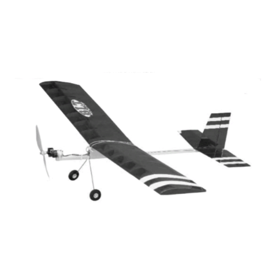
Airframe Weight: 2.4 oz
Fuse Length: 28-5/8 in
Wing Loading: 4.41 - 6.37 oz/sq ft
P.O. Box 788
Urbana, IL 61801
productsupport@greatplanes.com
Wingspan: 42 in
Wing Area: 294 sq in
(217) 398-8970
Entire Contents © Copyright 2002
Advertisement
Table of Contents

Related Manuals for GREAT PLANES BLT


Summary of Contents for GREAT PLANES BLT
-
Page 1: Instruction Manual
In that Great Planes has no control over the final assembly or material used for final assembly, no liability shall be assumed nor accepted for any damage resulting from the use by the user of the final user-assembled product. By the act of using the user-assembled product, the user accepts all resulting liability. -
Page 2: Table Of Contents
IMPORTANT BUILDING NOTES ....5 The BLT is a slow flying, high-wing model that is about as Patterns........6 simple to build as they get. -
Page 3: Decisions You Must Make
This is a list of items required to finish the BLT that must it; therefore, we cannot in any way guarantee the be purchased separately. -
Page 4: Chargers
Transparent MonoKote film is also suitable for covering mode. The Great Planes ElectriFly Peak Charger the BLT, because it is lighter and does not shrink as tightly (GPMM3000) is suitable for nickel-metal hydride as opaque MonoKote film (and is the covering that is on batteries, NiCds and transmitter battery packs. -
Page 5: Optional Supplies And Tools
(not to mention the aggravation!). For the best performance, the BLT must be built light. One 7. Sanding requires a light touch to avoid damage. We of the best ways to insure light weight is to build neatly and found the best method for sanding is to use light strokes in make good-fitting glue joints that require less glue. -
Page 6: Patterns
PATTERNS METRIC CONVERSION 1" = 25.4mm (conversion factor) 1/64" = .4mm 1" = 25.4mm 1/32" = .8mm 2" = 50.8mm 1/16" = 1.6mm 3" = 76.2mm 3/32" = 2.4mm 6" = 152.4mm 1/8" = 3.2mm 12" = 304.8mm 5/32" = 4mm 15"... -
Page 7: Build The Tail Surfaces
Build the Fin & Rudder 1. Cover the fin/rudder portion of the plan with wax paper or Great Planes Plan Protector. 6. Tape the leading edge of the rudder to the trailing edge of the fin so that the fin and rudder align at the top. Use a... -
Page 8: Build The Stabilizer & Elevator
Build the Stabilizer & Elevator 1. Cover the stabilizer/elevator portion of the plan with wax paper or Plan Protector. 6. In the right elevator half, use a hobby knife to cut the 1/16” (1.6mm) notch for the elevator control horn. 7. -
Page 9: Build The Wing
Start by building the left wing panel right side up over the left wing panel plan so your progress matches the photos. 1. Cover the left wing panel plan with Great Planes 5. Starting at the wing tip, glue the seven laser-cut 1/16"... - Page 10 7. Position the top 1/8" x 1/4" x 24" (3.2mm x 6.4mm x 609.6mm) balsa main spar in the rib notches with one end flush with the outside edge of the root rib and glue to all the ribs. 11. From a 1/32" x 3/4" x 24" (.8mm x 19mm x 609.6mm) balsa sheet, cut and glue shear webs, horizontally, to the top and bottom spars in the locations 8.
-
Page 11: Join The Wing Panels
Join the Wing Panels 1. Draw a vertical centerline on the laser-cut 1/16" ply dihedral brace. 14. From the remaining 1/16” balsa STTRF02 laser-cut sheet, cut two wing tip braces 5/16” x 6-1/8” (7.9mm x 155.5mm). Glue the wing tip brace on the inside of the W-1 wing tip rib. -
Page 12: Build The Fuselage
BUILD THE FUSELAGE Assemble the Fuselage Sides 1. With Great Planes Plan Protector positioned over the fuselage top view, pin the laser-cut 1/16” (1.6mm) fuselage bottom (the side with the “B” facing up) in position over the plan. 4. At the marks on the fuselage bottom, glue the five laser-cut 3/32"... - Page 13 9. Insert and glue the 3/8" x 3/8" x 1" (9.5mm x 9.5mm x 25.4mm) balsa nose reinforcement in the front of the fuselage so that it is flush with the sides, top and bottom. 12. Position the 1/16" (1.6mm) wire landing gear on the fuselage top, against the front of the wing pylon to act as a spacer.
-
Page 14: Finishing
Add Washout (wing twist) FINISHING An important characteristic of most airplanes is their ability to stall gently. One way to achieve this is with washout built into Final Sanding the wing. Washout is when the wing is twisted at the tips so that the TE of the wing is higher than the LE. -
Page 15: Completing Assembly
COMPLETING ASSEMBLY Mount the Stabilizer & Fin 4. With the TE of the fin flush with the aft end of the fuse, use CA to glue the fin along the center line of the stab, perpendicular to the top of the stab. 1. -
Page 16: Radio Installation
RADIO INSTALLATION ASSEMBLE THE GEAR DRIVE Follow these assembly instructions for the Great Planes ElectriFly ™ Mount the Servos T-280GD ESC motor system and gear drive (GPMG0430). 1. Before starting the radio installation, put the motor battery on your charger. Then, when the battery is required for the radio installation, it will be charged. -
Page 17: Mount The Motor
MOUNT THE MOTOR 3. The Basic Light Trainer will fly better if the motor is set with 1 to 2 degrees of right thrust. This can be accomplished by laying the fuselage on its side and using a protractor to angle the motor. - Page 18 5. Cut three 1/4" (6.4mm) long guide tubes from the 6-1/2" long white plastic tube. Slide the guide tubes over the forward pushrod. 6. 1/2" (12.7mm) from the end of the forward pushrod, 11. Reinstall the aft pushrod in the rudder control horn. make a slight bend.
-
Page 19: Install The Landing Gear
We recommend the following control surface throws: INSTALL THE LANDING GEAR Elevator: 5/8" up 5/8" down 1. Reinstall the wire landing gear over the fuselage, positioned under the pylon forward plate. Rudder: 7/8" left 7/8" right IMPORTANT: The balance and control throws for the Basic Light Trainer have been extensively tested. -
Page 20: Preflight
2. With all parts of the model installed (except for the motor Ground Inspection battery), lift the model at the balance point. If the tail drops, the model is “tail heavy”. If the nose drops, it is “nose heavy”. Use Before you fly you should perform one last overall a piece of cellophane tape to attach the motor battery to the inspection to make sure the model is truly ready to fly and... -
Page 21: Examine The Propeller
Where necessary an observer shall be utilized to supervise flying to avoid having 2. The ideal power source for the BLT system is a 6 to models fly in the proximity of full scale aircraft. -
Page 22: Flying
R/C pilot to check your model for airworthiness AND to teach you how to fly. No matter how stable or “forgiving” the BLT is, attempting to learn to fly on your own is dangerous and may result in destruction of your model or even injury to yourself and others. -
Page 23: Landing
Use these tags to identify your models. Landing Because the BLT flies slowly, it requires little room to land. Begin the landing approach by flying downwind at an altitude of approximately 20 feet [6 meters]. When the airplane is approximately 50 to 100 feet [15 to 30 meters] past you, reduce the motor power and make the “final”... - Page 24 TWO VIEW...
Need help?
Do you have a question about the BLT and is the answer not in the manual?
Questions and answers