
Related Manuals for Korenix JetI/O 6510


Summary of Contents for Korenix JetI/O 6510
- Page 1 Korenix JetI/O 6510 Industrial Intelligent Ethernet I/O Server User’s Manual Jan. 2008 (V0.1) www.korenix.com...
- Page 2 Korenix JetI/O 6510 Industrial Intelligent Ethernet I/O Server User’s Manual Copyright Notice Copyright © 2008 Korenix Technology Co., Ltd. All rights reserved. Reproduction in any form or by any means without permission is prohibited.
-
Page 3: Table Of Contents
Hardware Installation ......................4 Hardware Introduction..................4 Wiring Power Input....................5 Wiring I/O Connectors..................6 JetI/O 6510 Wiring Example ................6 Wiring Earth Ground .................... 7 Wiring Fast Ethernet Ports................... 7 Din-Rail Mounting Installation ................7 Preparation for Management .................... 9 Understand the Ethernet I/O Server Architecture .......... -
Page 4: Introduction
1 Introduction Welcome to Korenix JetI/O 6500 Series Industrial Managed Ethernet I/O Module User Manual. Following topics are covered in this chapter: 1.1 Overview of JetI/O 6500 Series 1.2 Package Checklist 1.3 JetI/O 6510 Introduction 1.4 JetI/O 6510 Product Specification... -
Page 5: Package Checklist
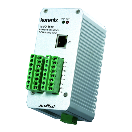
JetI/O 6510 Introduction JetI/O 6510 is a Block I/O module equipped with one Etherent port and 8 channels Analog Input connectors. Jet I /O 6510 provides 16 bit resolution and high accuracy for I/O data collecting. The analog input range can support from 150mV to 10V and 20mA. The values are most adopted in the industrial environemnt. -
Page 6: Jeti/O 6510 Product Specification
JetI/O 6510 Product Specification System Feature Network Protocols: IP, TCP, UDP, SNMP, HTTP, CPU: 16 bits/100MHZ, RISC-Based BOOTP, DHCP, Modbus/TCP, OPC Server Configuration: Windows Utility, Web browser, SNMP, SDRAM: 32K bytes DHCP Client, TFTP Server for firmware update Flash ROM: 512K bytes... -
Page 7: Hardware Installation
2 Hardware Installation This chapter includes hardware introduction, installation and configuration information. Following topics are covered in this chapter: 2.1 Hardware Introduction Dimension Appearance LED Indicators 2.2 Wiring Power Input 2.3 Wiring I/O Connectors 2.4 Wiring Ethernet Ports 2.5 DIN-Rail Mounting Installation Hardware Introduction Dimensions: 120 (H) x 55 (W) x 75 (D) mm... -
Page 8: Wiring Power Input
JetI/O 6510 Appearance: LED Indicators: System LED Power Input plugged and On (Green) System startup ready (Red) Ethernet LED Upper (LAN Activity) Orange On & Blinking Lower(10M/100M) 10M (Green Off) /100M(Green ON Wiring Power Input Follow below steps to wire JetI/O DC power inputs. -
Page 9: Wiring I/O Connectors
Follow the pin assignment to insert the wires into the front contacts on the terminal block connector. Tighten the wire-clamp screws to prevent the I/O wires from being loosened. The wiring diagram of the JetI/O 6510 is as below: Pin No... -
Page 10: Wiring Earth Ground
Wiring Earth Ground To ensure the system will not be damaged by noise or any electrical shock, we suggest you to make exact connection with JetI/O products with Earth Ground. On the bottom side of JetI/O 6500 Series, there is one power earth ground pin in the Power Input terminal block. - Page 11 Check if DIN-Rail clip is tightly attached on the track. d. To remove JetI/O 6500 from the track, reverse the steps above.
-
Page 12: Preparation For Management
3 Preparation for Management Before you start to configure the JetI/O, you need to know the system architecture of the JetI/O products, configure the device’s IP address, and then you can remotely manage the Ethernet I/O via the network. This chapter introduces the basic knowledge of the related technologies. - Page 13 address is 192.168.10.3. You can directly connect the JetI/O one after one to change its IP address. Or connect the JetI/Os to the same switch or network, then the host PC can modify the IP address via the switch or network. If you purchase several JetI/Os and connect them to the same network before change their IP address.
-
Page 14: Feature Configuration
4.5 Web UI 4.6 Modbus/TCP Command set 4.6.1 Introduction of Modbus/TCP protocol 4.6.2 JetI/O 6510 Modbus/TCP command set Block I/O Configuration Utility Block I/O Utility is the major JetI/O Configuration Utility. With this tool, you can browse the available units, view the status of each channel, configure the I/O settings, configure active alarms and conditions&Go logic rule. - Page 15 4. Type the name for the Block I/O Configuration Utility or use the default name, Block IO Utility (Korenix) for the program in the “Program Folder” field of the “Select Program Folder” window. Then click “Next”. 5. Click “Next” in the “Starting Copying File” window to continue the setup progress.
- Page 16 4.1.2 Device Scan 1. Lunch the Block IO Utility and then press “Open” to enable the network Interface. The right indicator will show “Green” after you opened the interface. Click “Cloos” can close the network interface. 2. Click “Scan” to open the “Scan Network Module(s)” popup window. Click Scan to start the searching.
- Page 17 4.1.3 JetI/O 6510 Configuration 4.1.3.1 Go to “General” page. You can view the current settings, modify the IP address, Subnet mask, Default Gateway, Enable or Disable DHCP Client mode, select the Input range of this device and check the Firmware version.
- Page 18 4.1.3.2 Go to “Data” page. You can monitor the current working voltage of each channel. Select the check box to monitor the info of the channel. Check Box Unselect the check box when you don’t want to monitor it. White Afte enabled the alarm feature of the channel, these is a white circle behind the channel.
-
Page 19: Block I/O Opc Server Utility
Block I/O OPC Server Utility 4.2.1 OPC Server Utility 1. Go to “Start” -> “Program”, then you can see the “Block IO Utility(Korenix) folder. There are 2 utilities are installed, Block IO OPC Server and Block IO Utility. 2. Open the “Block IO OPC Server”. - Page 20 4. Select “Add -> New Device”, the popup window “Driver Selection” will appear. (Only appear in the first time you add new device). Click “Add” and type the driver name and correct IP address. Click “OK” to next popup windows for Driver Selection. Use “Edit ->...
- Page 21 6. Select “Add -> New Group” to create new group for the later new tags you’ll create. Select “Add -> New Tag” and fill the “Tag Properties” in the popup window. Select the tag and “Edit –> Properties“, you can modify the tag properties. 7.
- Page 22 Channel: The channel ID. Value: The value of the channel, you can use “Monitor” to read them. Description: The description of this channel, you can munually change this value. 8. Select “View -> Monitor” to monitor the status of the tags. Or you can click the Monitor icon in the UI.
-
Page 23: Device Finder Utility
Device Finder Utility 1. Go to the “Utility -> Device Finder” folder. Click “DeviceFinder.exe” to run the program. 2. Click “Setting” of the DF Setting, you can configure the polling period time. 3. Click “Setup” of the EEPROM, you can see the info of the device. It’s good to do debugging. -
Page 24: Web Ui
Web UI Type the IP address of the device. Then you can access the embedded web browser of the I/O server. The web browser allows you monitor the information/status of each channels. How to Upgrade Firmware The JetI/O server allows you remotely upgrade the firmware to fix the known issues or to enhance the software features. - Page 25 target unit/units you want upgrade. Then press “Upgrade” to start the progress. The JetI/O can get dynamic IP and download file from the TFTP32. The popup window shows you the upgrading progress in TFTP32. 5. After firmware file downloading finished. The JetI/O server’s firmware can be upgraded automatically.
-
Page 26: Modbus/Tcp Command Set
SCADA/HMI or coding your own programs. The command set is helpful for you to find the value of each registers. Following topics are covered in this chapter: 5.1 Introduction of Modbus/TCP Protocol 5.2 JetI/O 6510 Modbus/TCP Address Mapping Introduction of Modbus/TCP Protocol 5.1.1 Modbus/TCP Protocol The Modbus protocol, developed by Gould-Modicon, is widely used in industrial communications to integrate PLC’s, computer, terminals and other various I/O devices. - Page 27 Negative Acknowledge received in the query. The slave attempted to read extended memory, but Memory Parity Error detected a parity error in the memory. JetI/O 6510 Modbus/TCP Address Mapping JetI/O 6510 Common Register Map (Holding Registers) Protocol Address Address Access Description...
- Page 28 (R: no used) W: AABB AABB:FF00H 000C 40013 Span calibration (R: no used) W: AABB AABB:FF00H JetI/O 6510 Special Register Map (Holding Registers) 000D 40014 Read/write Channel 0 Low alarm value R/W:AABB 000E 40015 Read/write Channel 0 High alarm value...
- Page 29 R/W:AABB 0016 40023 Read/write Channel 4 High alarm value R/W:AABB 0017 40024 Read/write Channel 5 Low alarm value R/W:AABB 0018 40025 Read/write Channel 5 High alarm value R/W:AABB 0019 40026 Read/write Channel 6 Low alarm value R/W:AABB 001A 40027 Read/write Channel 6 High alarm value R/W:AABB 001B 40028...
- Page 30 R: AABB(hex) W: AABB(hex) IP=AA.BB.X.X 0028 40041 (Write) Repeat enable SNMP Trap W: FF00(hex) JetI/O 6510 Analog Input Register Map (Input Register) 0000 30001 Analog input signal (Channel 0) Units: signed Input Range: ± 10V Return Value: D8F0 ~ 2710(-10000mV ~ +10000mV) Input Range: ±...
-
Page 31: Appendix
6 Appendix SNMP MIB An SNMP to I/O MIB file that can help you monitor I/O status with SNMP software. You can find the MIB file on the package. (I). Public- System MIB: Object ID Description Community, (OID) R/W Access The sysDescr directive is used to define the system Public, sysDescr... -
Page 32: Revision History
(II).Private MIB - Intelligent I/O Server - 6510 Object ID (OID) Description Community, R/W Access eioAin00Value Analog input signal (Channel 0) Private, SYNTAX: INTEGER ( 0..65535 ) Read Only eioAin01Value Analog input signal (Channel 1) Private, SYNTAX: INTEGER ( 0..65535 ) Read Only eioAin02Value Analog input signal (Channel 2)
Need help?
Do you have a question about the JetI/O 6510 and is the answer not in the manual?
Questions and answers