
Related Manuals for Korenix JetI/O 6510


Summary of Contents for Korenix JetI/O 6510
- Page 1 Korenix JetI/O 6510 Industrial Intelligent Ethernet I/O Server User Manual Sept. 2009 (V1.5) www.korenix.com...
- Page 2 Korenix JetI/O 6510 Industrial Intelligent Ethernet I/O Server User Manual Copyright Notice Copyright 2009 Korenix Technology Co., Ltd. All rights reserved Reproduction in any form or by any means without permission is prohibited.
-
Page 3: Table Of Contents
Index INTRODUCTION ......................1 I/O 6500 S ................1 VERVIEW OF ERIES ....................2 ACKAGE HECKLIST I/O 6510 I ..................2 NTRODUCTION I/O 6510 P ............... 3 RODUCT PECIFICATION HARDWARE INSTALLATION..................4 ..................4 ARDWARE NTRODUCTION ....................5 IRING OWER NPUT I/O C ................... -
Page 4: Introduction
1 Introduction Welcome to Korenix JetI/O 6500 Series Industrial Managed Ethernet I/O Server User Manual. Following topics are covered in this chapter: 1.1 Overview of JetI/O 6500 Series 1.2 Package Checklist 1.3 JetI/O 6510 Introduction 1.4 JetI/O 6510 Product Specification... -
Page 5: Package Checklist
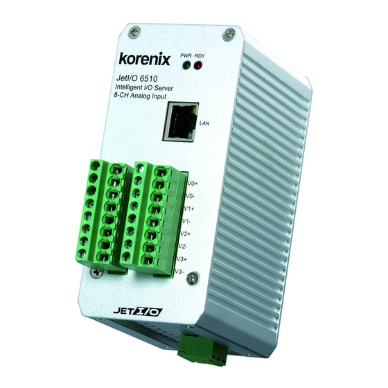
JetI/O 6510 Introduction JetI/O 6510 is an intelligent I/O Server equipped with one Ethernet port and 8 channels Analog Input connectors. JetI/O 6510 provides 16 bits resolution and high accuracy for I/O data collecting. The analog input range can support from 150mV to 10V and 20mA. -
Page 6: Jeti/O 6510 Product Specification
JetI/O 6510 Product Specification System Feature Network Protocols: IP, TCP, UDP, SNMP, HTTP, CPU: 100MHZ, RISC-Based BOOTP, DHCP, Modbus/TCP, OPC Server Configuration: Windows Utility, SNMP, DHCP Client, SDRAM: 32K bytes TFTP Server for firmware update Flash ROM: 512K bytes Windows Utility: Block I/O Utility... -
Page 7: Hardware Installation
2 Hardware Installation This chapter includes hardware introduction, installation and configuration information. Following topics are covered in this chapter: 2.1 Hardware Introduction Dimension Appearance LED Indicators 2.2 Wiring Power Input 2.3 Wiring I/O Connectors 2.4 Wiring Ethernet Ports 2.5 DIN-Rail Mounting Installation Hardware Introduction Dimensions: 120 (H) x 55 (W) x 75 (D) mm... -
Page 8: Wiring Power Input
JetI/O 6510 Appearance: LED Indicators: System LED Power Input plugged and On (Green) System startup ready (Red) Ethernet LED Upper (LAN Orange On & Blinking Activity) Lower(10M/100M) 10M (Green Off) /100M(Green ON Wiring Power Input Follow below steps to wire JetI/O DC power inputs. -
Page 9: Wiring I/O Connectors
Follow the pin assignment to insert the wires into the front contacts on the terminal block connector. Tighten the wire-clamp screws to prevent the I/O wires from being loosened. The wiring diagram of the JetI/O 6510 is as below: Pin No... -
Page 10: Wiring Earth Ground
Wiring Earth Ground To ensure the system will not be damaged by noise or any electrical shock, we suggest you to make exact connection with JetI/O products with Earth Ground. On the bottom side of JetI/O 6500 Series, there is one power earth ground pin in the Power Input terminal block. - Page 11 Lightly push the bottom of DIN-Rail clip into the track. Check if DIN-Rail clip is tightly attached on the track. d. Korenix suggests reserve at least 5mm interval distance between the JetI/O devices. This is good for heat dispersing.
-
Page 12: Preparation For Management
3 Preparation for Management Before you start to configure the JetI/O, you need to know the system architecture of the JetI/O products, configure the device’s IP address, and then you can remotely manage the Ethernet I/O via the network. This chapter introduces the basic knowledge of the related technologies. - Page 13 IP address. Or connect the JetI/Os to the same switch or network, then the host PC can modify the IP address via the switch or network. If you purchase several JetI/Os and connect them to the same network before change their IP address.
-
Page 14: Feature Configuration
4.4 Web UI 4.5 Modbus/TCP Command set 4.5.1 Introduction of Modbus/TCP protocol 4.5.2 JetI/O 6510 Modbus/TCP command set Block I/O Configuration Utility Block I/O Utility is the major JetI/O Configuration Utility. With this tool, you can browse the available units, view the status of each channel, configure the I/O settings, configure active alarms and Conditions&Go logic rule. - Page 15 6. As long as you see the “Setup Complete” window that means the progress is finished. Click “Finish” to exit the setup progress. 7. Go to “Start” -> “Program”, and then you can see the “Block IO Utility (Korenix) folder. There are 2 utilities are installed, Block IO OPC Server and Block IO Utility.
- Page 16 4.1.2 Device Finder Device Finder helps you search JetIO 6500 devices on the same physical subnet, even if their IP addresses are conflit or if their IP address setting are not on the same subnet with your host PC. Device Finder also helps you configure the IP address and upgrade firmware of the found devices.
- Page 17 3. Select the target units and click “Reboot” to reboot the device. You can reboot one or multiple units in one time. 4. Select the target units and click “Upgrade” to upload the new firmware. Please refer to the section 4.6 to know the detail step by step progress. 5.
- Page 18 Configuration utility provides are similar. Please find your model name and go to its configuration introduction chapter in below. 4.1.4 JetI/O 6510 Configuration 4.1.4.1 Go to “General” page. Once you select one of the existing I/O modules in the Network interface tree,...
- Page 19 It should be noticed that the privilege setting is required to gain access to do the further configuration options. When you install the I/O module in first time, the default password is “admin”. You just need to click on “Login” button and type the password of “Admin”...
- Page 20 the “Update” button. This setting will be affected after restarting the module. Note: After changed IP address or changed the DHCP client mode, the utility will automatically reboot the unit. Please rescan the devices after around 5 seconds. 4.1.4.2 Go to “Data” page. In this page, you could monitor the current working status of each channel on AI as well as the channels range configuration.
- Page 21 The Channels Range Configuration area, you can choose either “Fixed input range on all channels” or “Individual input range on all channels”. The factory default setting is “Fixed input range on all channels”. Just select the appropriate range from the “Input range” combo box and then click “Update” to take effect.
- Page 22 Alarm Channel: Select the channel. Alarm Mode: Enable or Disable High Alarm Value, Low Alarm Value: Type the value here. Update: Activate the new setting. 4.1.4.4 Go to “Logic Rules” page. In this page, you can configure the I/O logic rule. It allows you to define the logic operation and process rules in this utility and then download the rules to the I/O module.
- Page 23 Double click the Rule ID and then you can go to the Logic Rulle#ID Configuration page. Select “Enable” and configure the Condition and Actions then press “Apply” to enable the rule. Thus, when the “Conditions” is reached, the system automatically activates the “Actives”.
- Page 24 (AI-0 ≤ 5.0) AND Enable Flag-0 = OFF (AI-1 ≤ 8.0) Rule #1: If condition is equal to “(AI-0 > 5.0V) OR (AI-1 > 8.0V)”, the “Flag-0” is automatically “ON”. Again, configure the reverse way in the rule #2: If condition is equal to “(AI-0 ≤ 5.0V) AND (AI-1 ≤ 8.0V)”, the “Flag-0” is automatically “OFF”.
- Page 25 Each channel including all the internal flags on the source module can be mapping to channel including all the internal flags on different destination modules. The Peer-to-Peer I/O activity on all the modules not only supports the “one-to-one” mapping but also “multiple-to-one/from-one” and “one-to/from-multiple”...
- Page 26 further assignments for those internal flags which will mirror the remote internal flags on the corresponding remotely input module as defined on the field of “Remote IP address”. It could support up to 8 rules assignment. Press “Apply” to activate the new setting. After completing all configurations for Peer-to-Peer I/O activity, click “Save”...
- Page 27 Refer to above Figure as below, in the bottom field of this “Peer to Peer I/O” page is the motoring area. It is monitoring the status both on peer-to-peer I/O activity and internal flags. Click “Active Status” button, the dialog of peer-to-peer I/O active status will popup to represent the status code on peer-to-peer I/O activity.
- Page 28 4.1.4.6 Go to “SNMP” page. IP Setting: You can configure up to 4 SNMP Trap Server’s IP here. Type the IP address and press “Update” to activate the new setting. Click “Refresh” to reload the current SNMP trap server’s IP from registers. Once the SNMP trap has been activated by I/O login rule, you need to press “Reset”...
- Page 29 4.1.4.2 Follow the 4.1.3 to scan the network, you’ll find the models JetI/O currently supported. Click “Add” to add the models. 4.1.4.3 Follow the 4.1.4 to practice JetI/O configuration. Select the model and read or write status and configurations. As to how to operate the JetI/O configuration of other model, please refer to its manual.
- Page 30 4.1.6.1 Open Terminal Mode. Click Open and then select “Terminal”. The terminal emulation popup screen appears. 4.1.6.2 Single Command mode. Type the correct IP address of target unit in IP Address field, PLC address in the Command field. Then click “Enter” key. You can read the Response of the PLC address.
- Page 31 Type the correct IP address of target unit in IP Address field. Browse the text file to load the file. Example: Write below commands in Modbus test.txt file and browse it. 40001 40002 40003 40004 40005 4.1.6.5 Commands: Run Send to run the multiple commands. Run “Stop” to stop the program.
-
Page 32: Block I/O Opc Server Utility
Block I/O OPC Server Utility 1. Go to “Start” -> “Program”, and then you can see the “Block IO Utility (Korenix) folder. There are 2 utilities are installed, Block IO OPC Server and Block IO Utility. 2. Open the “Block IO OPC Server”. - Page 33 Figure 4.1 “Add” the “New Device”. Figure 4.2 “Driver Selection Window. Click “Add…” to next popup window. Figure 4.3 “Ethernet Driver” popup Window. Type the Driver Name and IP address for the device. Figure 4.4 Example: Add all the drivers for available models. If you have 5 models over the same network, add them and give them different name for identification in next steps.
- Page 34 5. Type the “Device Name” and select the “Device Type” and the “Driver” in the “Device Properties” window. Device Type means the JetI/O model name. Driver is the name you configured in last step. 6. Select “Add -> New Group” to create new group for the later new tags you’ll create. Select “Add ->...
- Page 35 Name: The name of the channel. You can manually change this value. Type: The input type of the channel. Channel: The channel ID. Value: The value of the channel, you can use “Monitor” to read them. Description: The description of this channel, you can manually change this value. 8.
-
Page 36: Snmp
Please note that there is only one DHCP server available over the same network. Otherwise the device may get the wrong IP. Since Device Finder builds in a BOOTP server, Korenix suggests you make sure there is only one DHCP/BOOTP server on the network when you upgrade the JetIO firmware. - Page 37 Notes: (a). Disable Firewall (b). Enable only one network card on your PC (c). Set a proper IP address with the same segment as the IP address of your PC (d). DON'T configure more than one IP address on the network interface. (e).
-
Page 38: Configuration Backup /Restore , Reset Default And Reboot
(e). Select a correct module firmware code (i.e., 6550_Fxxx.bin for JetIO 6550) 3. Press “Upgrade” button to pop up the Firmware Upgrade console. 4. Set a proper IP address for JetIO module boot loader. Please note that the IP address should be set to the same network segment of your PC. - Page 39 Select “Backup Config. to …” and “Restore Config. from …” command to backup and restore the configuration of the JetIO to/from a text file. It should be noticed that you will need to login first and then gain a privilege to do these functions. Click “Reset to default”...
- Page 40 [irange.conf.PLCAddr] 0=40011 1=40030 [snmp.trap.ips.PLCAddr] 0=40032:40040 [alarm.conf.PLCAddr] 0=40031 [ip.conf.Program] key=ip.conf var0=ip.ip var1=ip.mask var2=ip.gateway var3=ip.dhcp [alarm.limit.conf.Program] key=alm.limit var0=40014:40029...
-
Page 41: Modbus/Tcp Command Set
SCADA/HMI or coding your own programs. The command set is helpful for you to find the value of each registers. Following topics are covered in this chapter: 5.1 Introduction of Modbus/TCP Protocol 5.2 JetI/O 6510 Modbus/TCP Address Mapping Introduction of Modbus/TCP Protocol 5.1.1 Modbus/TCP Protocol The Modbus protocol, developed by Gould-Modicon, is widely used in industrial communications to integrate PLC’s, computer, terminals and other various I/O devices. -
Page 42: Jeti/O 6510 Modbus/Tcp Address Mapping
Modbus/TCP protocol. Please choose the type your application uses. Should you encounter problem on reading this, please contact our technical support engineer, korecare@korenix.com JetI/O 6510 Common Register Map (Holding Registers, Function Code = 03) Protocol Address Address... - Page 43 R/W:AABB AABB:0001H~00FFH (0.1*AABB)=Cycle Time (sec) 0002 40003 R: Read the host-watchdog status W: Reset the host-watchdog status R:AABB AABB:0000H (remote module OK) AABB:FF00H (host-watchdog fail) W: AABB AABB:FF00H(reset) 0003 40004 Read the firmware version R:AAAA AAAA:F204H (HEX) 0004 40005 Read module name R:AAAA AAAA: 6510H (HEX) 0005...
- Page 44 W: AABB AABB:FF00H (Warning: You should calibrate the value for the selected input range by the certificated calibrator when need.) JetI/O 6510 Special Register Map (Holding Registers, Function Code = 03) 000D 40014 Read/write Channel 0 Low alarm value R/W:AABB...
- Page 45 R/W:AABB 0017 40024 Read/write Channel 5 Low alarm value R/W:AABB 0018 40025 Read/write Channel 5 High alarm value R/W:AABB 0019 40026 Read/write Channel 6 Low alarm value R/W:AABB 001A 40027 Read/write Channel 6 High alarm value R/W:AABB 001B 40028 Read/write Channel 7 Low alarm value R/W:AABB 001C 40029...
- Page 46 0022 40035 (Read/Write)SNMP Trap IP2 Lo-Word R: AABB(hex) W: AABB(hex) IP=X.X.AA.BB 0023 40036 (Read/Write)SNMP Trap IP2 Lo-Word R: AABB(hex) W: AABB(hex) IP=X.X.AA.BB 0024 40037 (Read/Write)SNMP Trap IP3 Hi-Word R: AABB(hex) W: AABB(hex) IP=AA.BB.X.X 0025 40038 (Read/Write)SNMP Trap IP3 Lo-Word R: AABB(hex) W: AABB(hex) IP=X.X.AA.BB 0026...
- Page 47 Input code=08H: ± 10V 002B 40044 Read AD span Calibration Coefficients R:AABB(bit 16~23) (factory default calibration value) Input code=08H: ± 10V 002C 40045 Read AD span Calibration Coefficients R:00AA(bit 0~15) (factory default calibration value) Input code=08H: ± 10V 002D 40046 Read AD offset Calibration Coefficients R:AABB(bit 16~23) (factory default calibration value)
- Page 48 value) Input code=0AH: ± 1V 0033 40052 Read AD span Calibration Coefficients R:AABB(bit 16~23) (factory default calibration value) Input code=0AH: ± 1V 0034 40053 Read AD span Calibration Coefficients R:00AA(bit 0~15) (factory default calibration value) Input code=0AH: ± 1V 0035 40054 Read AD offset Calibration Coefficients R:AABB(bit 16~23) (factory default...
- Page 49 003A 40059 Read AD offset Calibration Coefficients R:00AA(bit 0~15) (factory default calibration value) Input code=0CH: ± 100mV 003B 40060 Read AD span Calibration Coefficients R:AABB(bit 16~23) (factory default calibration value) Input code=0CH: ± 100mV 003C 40061 Read AD span Calibration Coefficients R:00AA(bit 0~15) (factory default calibration value) Input code=0CH: ±...
- Page 50 W: xxxxxxxxxxxxxxxx(bit) 0: disable 1: enable (write to Flash RAM) 01F4 40501 (Read/Write) RuleEnable Logic 0~15 R: xxxxxxxxxxxxxxxx(bit) W: xxxxxxxxxxxxxxxx(bit) 0: disable 1: enable (write to Flash RAM) 01F5 40502 (Read/Write) Select “OR” or “AND” R:AAAA(hex) W: AAAA (hex) AAAA:xxxxxxxxxxxxxxxx X: 0 “OR”...
- Page 51 D: condition #0 Logic AI Channel(write to Flash RAM) 01F8 40505 (Read/Write) Select condition AI channel (or Auxflag channel) for Rule 2 R: ABCD(hex) W: ABCD(hex) A: condition #3 Logic AI Channel B: condition #2 Logic AI Channel C: condition #1 Logic AI Channel D: condition #0 Logic AI Channel(write to Flash RAM) 01F9...
- Page 52 R: ABCD(hex) W: ABCD(hex) A: condition #3 Logic AI Channel B: condition #2 Logic AI Channel C: condition #1 Logic AI Channel D: condition #0 Logic AI Channel(write to Flash RAM) 01FC 40509 (Read/Write) Select condition AI channel (or Auxflag channel) for Rule 6 R: ABCD(hex) W: ABCD(hex)
- Page 53 B: condition #2 Logic AI Channel C: condition #1 Logic AI Channel D: condition #0 Logic AI Channel(write to Flash RAM) 01FF 40512 (Read/Write) Select condition AI channel (or3Auxflag channel) for Rule 9 R: ABCD(hex) W: ABCD(hex) A: condition #3 Logic AI Channel B: condition #2 Logic AI Channel C: condition #1 Logic AI Channel D: condition #0 Logic AI Channel(write to Flash...
- Page 54 RAM) 0202 40515 (Read/Write) Select condition AI channel (or Auxflag channel) for Rule 12 R: ABCD(hex) W: ABCD(hex) A: condition #3 Logic AI Channel B: condition #2 Logic AI Channel C: condition #1 Logic AI Channel D: condition #0 Logic AI Channel(write to Flash RAM) 0203 40516...
- Page 55 R: ABCD(hex) W: ABCD(hex) A: condition #3 Logic AI Channel B: condition #2 Logic AI Channel C: condition #1 Logic AI Channel D: condition #0 Logic AI Channel(write to Flash RAM) 0206 40519 (Read/Write) Select Operators condition for Rule 0 R: ABCD(hex) W: ABCD(hex) A: Operators condition #3 Logic...
- Page 56 B: Operators condition #2 Logic C: Operators condition #1 Logic D: Operators condition #0 Logic Value: 0 : ON (Auxflag) 1:OFF (Auxflag) 2:Lo-Hi (Auxflag) 3:Hi-Lo (Auxflag) 4: “=” (AIValue = SetAIValue) 5:”>” (AIValue > SetAIValue) 6:”<” (AIValue < SetAIValue) 7:”>=” (AIValue >= SetAIValue) 8:”<=”...
- Page 57 7:”>=” (AIValue >= SetAIValue) 8:”<=” (AIValue <= SetAIValue) (write to Flash RAM) 0209 40522 (Read/Write) Select Operators condition for Rule 3 R: ABCD(hex) W: ABCD(hex) A: Operators condition #3 Logic B: Operators condition #2 Logic C: Operators condition #1 Logic D: Operators condition #0 Logic Value: 0 : ON (Auxflag)
- Page 58 0 : ON (Auxflag) 1:OFF (Auxflag) 2:Lo-Hi (Auxflag) 3:Hi-Lo (Auxflag) 4: “=” (AIValue = SetAIValue) 5:”>” (AIValue > SetAIValue) 6:”<” (AIValue < SetAIValue) 7:”>=” (AIValue >= SetAIValue) 8:”<=” (AIValue <= SetAIValue) (write to Flash RAM) 020B 40524 (Read/Write) Select Operators condition for Rule 5 R: ABCD(hex) W: ABCD(hex) A: Operators condition #3 Logic...
- Page 59 R: ABCD(hex) W: ABCD(hex) A: Operators condition #3 Logic B: Operators condition #2 Logic C: Operators condition #1 Logic D: Operators condition #0 Logic Value: 0 : ON (Auxflag) 1:OFF (Auxflag) 2:Lo-Hi (Auxflag) 3:Hi-Lo (Auxflag) 4: “=” (AIValue = SetAIValue) 5:”>”...
- Page 60 4: “=” (AIValue = SetAIValue) 5:”>” (AIValue > SetAIValue) 6:”<” (AIValue < SetAIValue) 7:”>=” (AIValue >= SetAIValue) 8:”<=” (AIValue <= SetAIValue) (write to Flash RAM) 020E 40527 (Read/Write) Select Operators condition for Rule 8 R: ABCD(hex) W: ABCD(hex) A: Operators condition #3 Logic B: Operators condition #2 Logic C: Operators condition #1 Logic D: Operators condition #0 Logic...
- Page 61 C: Operators condition #1 Logic D: Operators condition #0 Logic Value: 0 : ON (Auxflag) 1:OFF (Auxflag) 2:Lo-Hi (Auxflag) 3:Hi-Lo (Auxflag) 4: “=” (AIValue = SetAIValue) 5:”>” (AIValue > SetAIValue) 6:”<” (AIValue < SetAIValue) 7:”>=” (AIValue >= SetAIValue) 8:”<=” (AIValue <= SetAIValue) (write to Flash RAM) 0210 40529...
- Page 62 8:”<=” (AIValue <= SetAIValue) (write to Flash RAM) 0211 40530 (Read/Write) Select Operators condition for Rule 11 R: ABCD(hex) W: ABCD(hex) A: Operators condition #3 Logic B: Operators condition #2 Logic C: Operators condition #1 Logic D: Operators condition #0 Logic Value: 0 : ON (Auxflag) 1:OFF (Auxflag)
- Page 63 1:OFF (Auxflag) 2:Lo-Hi (Auxflag) 3:Hi-Lo (Auxflag) 4: “=” (AIValue = SetAIValue) 5:”>” (AIValue > SetAIValue) 6:”<” (AIValue < SetAIValue) 7:”>=” (AIValue >= SetAIValue) 8:”<=” (AIValue <= SetAIValue) (write to Flash RAM) 0213 40532 (Read/Write) Select Operators condition for Rule 13 R: ABCD(hex) W: ABCD(hex) A: Operators condition #3 Logic...
- Page 64 W: ABCD(hex) A: Operators condition #3 Logic B: Operators condition #2 Logic C: Operators condition #1 Logic D: Operators condition #0 Logic Value: 0 : ON (Auxflag) 1:OFF (Auxflag) 2:Lo-Hi (Auxflag) 3:Hi-Lo (Auxflag) 4: “=” (AIValue = SetAIValue) 5:”>” (AIValue > SetAIValue) 6:”<”...
- Page 65 5:”>” (AIValue > SetAIValue) 6:”<” (AIValue < SetAIValue) 7:”>=” (AIValue >= SetAIValue) 8:”<=” (AIValue <= SetAIValue) (write to Flash RAM) 0216 40535 (Read/Write) Select THEN Auxflag action for Rule 0 R: ABCD(hex) W: ABCD(hex) A: condition #3 Logic Auxflag Channel B: condition #2 Logic Auxflag Channel C: condition #1 Logic Auxflag Channel D: condition #0 Logic Auxflag Channel(write to...
- Page 66 0219 40538 (Read/Write) Select THEN Auxflag action for Rule 3 R: ABCD(hex) W: ABCD(hex) A: condition #3 Logic Auxflag Channel B: condition #2 Logic Auxflag Channel C: condition #1 Logic Auxflag Channel D: condition #0 Logic Auxflag Channel(write to Flash RAM) 021A 40539 (Read/Write) Select THEN Auxflag action for Rule 4...
- Page 67 C: condition #1 Logic Auxflag Channel D: condition #0 Logic Auxflag Channel(write to Flash RAM) 021D 40542 (Read/Write) Select THEN Auxflag action for Rule 7 R: ABCD(hex) W: ABCD(hex) A: condition #3 Logic Auxflag Channel B: condition #2 Logic Auxflag Channel C: condition #1 Logic Auxflag Channel D: condition #0 Logic Auxflag Channel(write to Flash RAM)
- Page 68 A: condition #3 Logic Auxflag Channel B: condition #2 Logic Auxflag Channel C: condition #1 Logic Auxflag Channel D: condition #0 Logic Auxflag Channel(write to Flash RAM) 0221 40546 (Read/Write) Select THEN Auxflag action for Rule 11 R: ABCD(hex) W: ABCD(hex) A: condition #3 Logic Auxflag Channel B: condition #2 Logic Auxflag Channel C: condition #1 Logic Auxflag Channel...
- Page 69 R: ABCD(hex) W: ABCD(hex) A: condition #3 Logic Auxflag Channel B: condition #2 Logic Auxflag Channel C: condition #1 Logic Auxflag Channel D: condition #0 Logic Auxflag Channel(write to Flash RAM) 0225 40550 (Read/Write) Select THEN Auxflag action for Rule 15 R: ABCD(hex) W: ABCD(hex) A: condition #3 Logic Auxflag Channel...
- Page 70 5: SNMP Trap (write to Flash RAM) 0227 40552 (Read/Write) Select Operators Action for Rule 1 R: ABCD(hex) W: ABCD(hex) A: Operators Action #3 Logic B: Operators Action #2 Logic C: Operators Action #1 Logic D: Operators Action #0 Logic Value: 0 : ON (Auxflag) 1: OFF (Auxflag)
- Page 71 0229 40554 (Read/Write) Select Operators Action for Rule 3 R: ABCD(hex) W: ABCD(hex) A: Operators Action #3 Logic B: Operators Action #2 Logic C: Operators Action #1 Logic D: Operators Action #0 Logic Value: 0 : ON (Auxflag) 1: OFF (Auxflag) 2: reserved 3: reserved 4: reserved...
- Page 72 R: ABCD(hex) W: ABCD(hex) A: Operators Action #3 Logic B: Operators Action #2 Logic C: Operators Action #1 Logic D: Operators Action #0 Logic Value: 0 : ON (Auxflag) 1: OFF (Auxflag) 2: reserved 3: reserved 4: reserved 5: SNMP Trap (write to Flash RAM) 022C 40557 (Read/Write) Select Operators Action for Rule 6...
- Page 73 W: ABCD(hex) A: Operators Action #3 Logic B: Operators Action #2 Logic C: Operators Action #1 Logic D: Operators Action #0 Logic Value: 0 : ON (Auxflag) 1: OFF (Auxflag) 2: reserved 3: reserved 4: reserved 5: SNMP Trap (write to Flash RAM) 022E 40559 (Read/Write) Select Operators Action for Rule 8...
- Page 74 A: Operators Action #3 Logic B: Operators Action #2 Logic C: Operators Action #1 Logic D: Operators Action #0 Logic Value: 0 : ON (Auxflag) 1: OFF (Auxflag) 2: reserved 3: reserved 4: reserved 5: SNMP Trap (write to Flash RAM) 0230 40561 (Read/Write) Select Operators Action for Rule 10...
- Page 75 B: Operators Action #2 Logic C: Operators Action #1 Logic D: Operators Action #0 Logic Value: 0 : ON (Auxflag) 1: OFF (Auxflag) 2: reserved 3: reserved 4: reserved 5: SNMP Trap (write to Flash RAM) 0232 40563 (Read/Write) Select Operators Action for Rule 12 R: ABCD(hex) W: ABCD(hex) A: Operators Action #3 Logic...
- Page 76 C: Operators Action #1 Logic D: Operators Action #0 Logic Value: 0 : ON (Auxflag) 1: OFF (Auxflag) 2: reserved 3: reserved 4: reserved 5: SNMP Trap (write to Flash RAM) 0234 40565 (Read/Write) Select Operators Action for Rule 14 R: ABCD(hex) W: ABCD(hex) A: Operators Action #3 Logic...
- Page 77 D: Operators Action #0 Logic Value: 0 : ON (Auxflag) 1: OFF (Auxflag) 2: reserved 3: reserved 4: reserved 5: SNMP Trap (write to Flash RAM) 0236 40567 (Read/Write) Condition Enable for Rule 0~3 R: ABCD(hex) W: ABCD(hex) A: xxxx x= 0:disable 1:enable rule 3 B: xxxx x= 0:disable 1:enable rule 2 C: xxxx x= 0:disable 1:enable rule 1 D: xxxx x= 0:disable 1:enable rule 0...
- Page 78 C: xxxx x= 0:disable 1:enable rule 9 D: xxxx x= 0:disable 1:enable rule 8 (write to Flash RAM) 0239 40570 (Read/Write) Condition Enable for Rule 12~15 R: ABCD(hex) W: ABCD(hex) A: xxxx x= 0:disable 1:enable rule 15 B: xxxx x= 0:disable 1:enable rule 14 C: xxxx x= 0:disable 1:enable rule 12 D: xxxx x= 0:disable 1:enable rule 12 (write to Flash RAM)
- Page 79 W: ABCD(hex) A: xxxx x= 0:disable 1:enable rule 11 B: xxxx x= 0:disable 1:enable rule 10 C: xxxx x= 0:disable 1:enable rule 9 D: xxxx x= 0:disable 1:enable rule 8 (write to Flash RAM) 023D 40574 (Read/Write) Action Enable for Rule 12~15 R: ABCD(hex) W: ABCD(hex) A: xxxx x= 0:disable 1:enable rule 15...
- Page 80 R/W: ABCD (write to Flash RAM) 0246 40583 (Read/Write) set “if logic” AI value for rule 2 #0 R/W: ABCD (write to Flash RAM) 0247 40584 (Read/Write) set “if logic” AI value for rule 2 #1 R/W: ABCD (write to Flash RAM) 0248 40585 (Read/Write) set “if logic”...
- Page 81 0254 40597 (Read/Write) set “if logic” AI value for rule 5 #2 R/W: ABCD (write to Flash RAM) 0255 40598 (Read/Write) set “if logic” AI value for rule 5 #3 R/W: ABCD (write to Flash RAM) 0256 40599 (Read/Write) set “if logic” AI value for rule 6 #0 R/W: ABCD (write to Flash RAM) 0257 40600...
- Page 82 R/W: ABCD (write to Flash RAM) 0263 40612 (Read/Write) set “if logic” AI value for rule 9 #1 R/W: ABCD (write to Flash RAM) 0264 40613 (Read/Write) set “if logic” AI value for rule 9 #2 R/W: ABCD (write to Flash RAM) 0265 40614 (Read/Write) set “if logic”...
- Page 83 0271 40626 (Read/Write) set “if logic” AI value for rule12 #3 R/W: ABCD (write to Flash RAM) 0272 40627 (Read/Write) set “if logic” AI value for rule 13 #0 R/W: ABCD (write to Flash RAM) 0273 40628 (Read/Write) set “if logic” AI value for rule 13 #1 R/W: ABCD (write to Flash RAM) 0274 40629...
- Page 84 B: condition #2 C: condition #1 D: condition #0 027F 40640 (Read/Write) select condition channel for PTP R/W: ABCD (write to Flash RAM) A: condition #7 B: condition #6 C: condition #5 D: condition #4 0280 40641 (Read/Write) select action channel for PTP R/W: ABCD (write to Flash RAM) A: condition #3 B: condition #2...
- Page 85 1:enable(write to Flash RAM) 0284 40645 (Read/Write) Mirror to(client) or Mirror from(server) R: 000A(hex) W: 000A(hex) A: 0: Mirror to(client) 1: Mirror from(server) 2: “Mirror to” and “ Mirror from” simultaneously (write to Flash RAM) 0285 40646 (Read/Write) PTP IP address ip[0] low word for server R: AABB W: AABB 0286...
- Page 86 W: AABB 028C 40653 (Read/Write) PTP IP address ip[3] hi word for server R: AABB W: AABB 028D 40654 (Read/Write) PTP IP address ip[4] low word for server R: AABB W: AABB 028E 40655 (Read/Write) PTP IP address ip[4] hi word for server R: AABB W: AABB 028F...
- Page 87 R: AABB W: AABB 0296 40663 (Read/Write) PTP IP address ip[8] hi word for client R: AABB W: AABB 0297 40664 (Read/Write) internal flags R/W: xxxxxxxxxxxxxxxx X:0 or 1 0298 40665 (Read) error code of peer to peer for client Error Code=0;...
- Page 88 Error Code=2; Remote Module Not Found Error Code=FFFF; Not Enabled 029C 40669 (Read) error code of peer to peer #4 for server Error Code=0; OK Error Code=1; Requested Content Not Satisfiable Error Code=2; Remote Module Not Found Error Code=FFFF; Not Enabled 029D 40670 (Read) error code of peer to peer #5 for server...
- Page 89 Error Code=1; Requested Content Not Satisfiable Error Code=2; Remote Module Not Found Error Code=FFFF; Not Enabled JetI/O 6510 Analog Input Register Map (Input Register, Function Code = 04) 0000 30001 Analog input signal (Channel 0) Units: signed Input Range: ± 10V...
- Page 90 the same data format as Channel 0 0006 30007 Analog input signal (Channel 6) the same data format as Channel 0 0007 30008 Analog input signal (Channel 7) the same data format as Channel 0...
-
Page 91: Appendix
6 Appendix SNMP MIB An SNMP to I/O MIB file that can help you monitor I/O status with SNMP software. You can find the MIB file on the package. (I). Public- System MIB: Object ID Description Community, (OID) R/W Access sysDescr The sysDescr directive is used to define Public,... - Page 92 fully-qualified domain name. SYNTAX: DisplayString (SIZE (0..31)) sysLocation The sysLocation directive is used to Public, define the location of the host on which Read Only the SNMP agent (server) is running. This directive is used for the sysLocation object instance of the MIB-II. SYNTAX: DisplayString (SIZE (0..31)) (II).Private MIB –...
- Page 93 SYNTAX: INTEGER ( 0..65535 ) Read Only ch7-Value Analog input signal (Channel 7) Private, SYNTAX: INTEGER ( 0..65535 ) Read Only...
-
Page 94: Revision History
Revision History Version Description Date Update “General” page Sept. 1, Update “Alarm” page 2009 Add “Logic Rules” page Add “Peer to Peer I/O” page Add “SNMP” page Add configuration backup/restore Dec. 24, 1. Simply firmware upgrade procedure 2008 Add description for Input Range of Current 1.21 Jun. - Page 95 1.11 Update Modbus/TCP Reset Status register. Feb. 20, 2008 Add Note for IP changed, Trap types, update latest Feb. 12, datasheet info, and correct some wordings. 2008 First Release version Jan. 30, Update the Data page description and some 2008 wording.
Need help?
Do you have a question about the JetI/O 6510 and is the answer not in the manual?
Questions and answers