Table of Contents
Advertisement
Quick Links
Download this manual
See also:
User Manual
Advertisement
Table of Contents

Related Manuals for Moxa Technologies PCI Express Board


Summary of Contents for Moxa Technologies PCI Express Board
- Page 1 PCI Express Board User’s Manual Multiport Serial Board for PCI Express Bus Fourth Edition, December 2008 www.moxa.com/product © 2008 Moxa Inc. All rights reserved. Reproduction without permission is prohibited.
-
Page 2: Copyright Notice
PCI Express Board User’s Manual The software described in this manual is furnished under a license agreement and may be used only in accordance with the terms of that agreement. Copyright Notice Copyright © 2008 Moxa Inc. All rights reserved. -
Page 3: Table Of Contents
Table of Contents Chapter 1 Introduction....................1-1 Overview ..........................1-2 Applications ........................1-3 Features ..........................1-3 Package Checklist ......................1-3 Installation Flowchart......................1-4 Chapter 2 Hardware Installation ................2-1 CP-118EL Dimensions ....................... 2-2 DIP Switch Settings (CP-118EL only) ................2-2 CP-168EL Dimensions (Unit= mm)................... 2-3 CP-104EL Dimensions (Unit= mm)................... - Page 4 Device Side Pin Assignments ................. 5-7 CP-104EL........................... 5-9 Board Side Pin Assignments—Female DB44............5-9 Device Side Pin Assignments ................5-10 CP-102E ..........................5-11 Board Side Pin Assignments—Male DB9 ............5-11 CP-102EL..........................5-11 Board Side Pin Assignments—Female DB25............5-11 Device Side Pin Assignments ................5-12 CP-132EL/CP-132EL-I....................
-
Page 5: Chapter 1 Introduction
Introduction Chapter 1 Moxa’s PCI Express serial boards meet the new slot standard for expansion boards, and work with any PCI Express slots. The boards have multiple RS-232/422/485 serial ports for connecting data acquisition equipment and other serial devices to a PC. This chapter covers the following topics: Overview Applications... -
Page 6: Overview
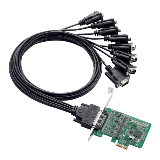
PCI Express Board User’s Manual Introduction Overview Moxa’s new PCI Express Multiport Serial Boards, named CP-118EL, CP-168EL, and CP-104EL, are designed for POS and ATM applications and for use by industrial automation system manufacturers and system integrators. The boards are compatible with all popular operating systems, and each of them supports data rates of up to 921.6 Kbps, and provides full modem... -
Page 7: Applications
• Drivers for all major industrial platforms—Windows 2000, Windows XP/2003/Vista/2008 (32-bit/64-bit), DOS, Linux (32-bit/64-bit), SCO, FreeBSD 4.x/5.x Package Checklist The following items are included in the PCI Express board package: • PCI Express serial board • Document and Software CD-ROM •... -
Page 8: Installation Flowchart
PCI Express Board User’s Manual Introduction Installation Flowchart The following flowchart provides a brief summary of the procedure you should follow to install the PCI Express boards and also provides references to chapters with more detailed information: Use the onboard DIP Switches to select the data transmission mode for each port. -
Page 9: Chapter 2 Hardware Installation
Chapter 2 This chapter describes the PCI Express Series hardware installation procedure. Since the BIOS automatically assigns the PCI Express board’s IRQ number and I/O addresses, you must plug in the board before installing the driver. This chapter covers the following topics:... -
Page 10: Cp-118El Dimensions
PCI Express Board User’s Manual Hardware Installation CP-118EL Dimensions 132 mm (5.20 in) 46.9 mm (1.85 in) NOTE: Use JP1/2/3/4/5/6/7/8 to activate the Termination Resistors for ports 1/2/3/4/5/6/7/8. Open Termination Resistor is NOT active Short Termination Resistor is ACTIVE DIP Switch Settings (CP-118EL only) CP-118EL has three onboard DIP Switch arrays, each with 8 switches, shown in the table below and on the listed board (see the above block diagram) as S1, S2, and S3. -
Page 11: Cp-168El Dimensions (Unit= Mm)
PCI Express Board User’s Manual Hardware Installation CP-168EL Dimensions (Unit= mm) 102 mm (4.02 in) 46.9 mm (1.85 in) CP-104EL Dimensions (Unit= mm) 100 mm (3.94 in) 46.9 mm (1.85 in) -
Page 12: Cp-102E Dimensions (Unit: Mm)
PCI Express Board User’s Manual Hardware Installation CP-102E Dimensions (Unit: mm) 113.36 MOXA 59.05 CP-102EL Dimensions (Unit: mm) 113.4 101.97 MOXA 59.1... -
Page 13: Cp-132El Dimensions (Unit: Mm)
PCI Express Board User’s Manual Hardware Installation CP-132EL Dimensions (Unit: mm) 113.4 101.97 MOXA 59.1 CP-132EL-I Dimensions (Unit: mm) 115.4 103.97 MOXA 59.1... -
Page 14: Cp-114El Dimensions (Unit: Mm)
PCI Express Board User’s Manual Hardware Installation CP-114EL Dimensions (Unit: mm) 116.36 104.93 MOXA 59.06 CP-114EL-I Dimensions (Unit: mm) 115.4 103.97 MOXA 59.1... -
Page 15: Plugging The Board Into An Expansion Slot
Step 8: Power on the PC. The BIOS will automatically set the IRQ and I/O address. NOTE Each Moxa PCI Express board uses one unique IRQ and I/O address, both of which are assigned automatically by the PCI BIOS. Step 9: Proceed with the software installation discussed in the next chapter, “Software... -
Page 16: Chapter 3 Software Installation
Software Installation Chapter 3 This chapter gives installation, configuration, and update/removal procedures for the driver for Windows 2000, Windows 2003/XP/Vista/2008 (32-bit/64-bit), DOS, Linux (32-bit/64-bit), and SCO, and WinCE 5.0. Before proceeding with the software installation, complete the hardware installation discussed in the previous chapter, “Hardware Installation.” Refer to the next chapter, “Serial Programming Tools,”... -
Page 17: Windows Drivers
The PCI Express board and ports are ready to use. WARNING If you are installing a PCI Express board on an ASUS A8N Series (AMD CPU) motherboard and the installation process hangs the first time, then restart the PC to reinstall it. NOTE... -
Page 18: Windows 2008/Vista (32-Bit/64-Bit)
PCI Express slot(s). NOTE If you have already installed a CP-114EL or other Moxa PCI Express board in your computer, and you are installing additional boards, Windows 2008/Vista will automatically detect and install the new board(s) the next time you boot up the computer. In this case, proceed directly to the next section, “Configuring the Ports,”... - Page 19 PCI Express Board User’s Manual Software Installation 2. The Found New Hardware – PCI Serial Port window will open automatically. This window will offer to connect to the Windows update site to search for a driver. Select Don’t search online.
- Page 20 PCI Express Board User’s Manual Software Installation 4. Select Search for driver software in this location, select Include subfolders, and then click Browse. If the system is a 32-bit (x86) platform, navigate to the \CP-114EL Series\Software\Windows 2008_Vista\x86 folder on the CD. If the system is a 64-bit (x64) platform, navigate to the \CP-114EL Series\Software\Windows 2008_Vista\x64 folder on the CD, and then click Next to continue.
- Page 21 PCI Express Board User’s Manual Software Installation The following figure shows the path for x64. 5. Wait while the installation wizard searches for the correct drivers. The next window that opens cautions you that although this software has not passed Windows Logo testing, the driver has been tested and shown that it can support the Windows OS.
- Page 22 PCI Express Board User’s Manual Software Installation 6. Wait while the driver software is installed. The next window shows the model name of the board, and indicates that Windows has completed the driver installation. Click Close to proceed with the rest of the installation procedure.
- Page 23 PCI Express Board User’s Manual Software Installation 8. Select Browse my computer for driver software (advanced). 9. Select Search for driver software in this location, select Include subfolders, and then click Browse. If the system is a 32-bit (x86) platform, navigate to the \CP-114EL Series\Software\Windows 2008_Vista\x86 folder on the CD.
- Page 24 PCI Express Board User’s Manual Software Installation The following figure shows the path for x64. 10. Wait while the installation wizard searches. The next window that opens cautions you that although this software has not passed Windows Logo testing, the driver has been tested and shown that it can support the Windows OS.
- Page 25 PCI Express Board User’s Manual Software Installation 11. After all files have been copied to the system, the software for this device has been successfully installed window will open to indicate that it has finished installing Port 0. Port installation procedure is complete when Port 0 has been set up.
-
Page 26: Configuring The Ports
PCI Express Board User’s Manual Software Installation Configuring the Ports After the driver has been installed, use Device Manager to configure the CP-114EL serial ports. 1. Click Start → Settings → Control Panel → System, select the Hardware tab, and then click Device Manager. - Page 27 PCI Express Board User’s Manual Software Installation 3. Click the port you would like to configure to highlight it, and then click Port Setting. 4. Select a COM number for the port from the Port Number pull-down list. 5. Select the Auto Enumerating COM Number option to map subsequent ports automatically.
-
Page 28: Using Event Log
PCI Express Board User’s Manual Software Installation 8. If you use the CP-114EL, CP-114EL-I, CP-132EL, CP-132EL-I, select Interface (RS-232, RS-422, 2-wire RS-485, 4-wire RS-485) and Termination Resistor (120Ω, Enable or Disable) to configure. Take CP-114EL for example. If you would like to configure as RS-422 and no Termination Resistor, please see figures below. -
Page 29: Removing The Driver
PCI Express Board User’s Manual Software Installation Removing the Driver 1. To uninstall the driver, click Start → Settings → Control Panel → System, select the Hardware tab, and then click Device Manager. Use the mouse to place the cursor over the CP-114EL Series board under Multi-port serial adapters, and then click the right mouse button. -
Page 30: Windows 2003/Xp (32-Bit/64-Bit)
PCI Express slot(s). NOTE If you have already installed a CP-118EL or other Moxa PCI Express board in your computer, and you are installing additional boards, Windows 2003/XP will automatically detect and install the new board(s) the next time you boot up the computer. In this case, proceed directly to the next section, “Configuring the Ports,”... - Page 31 PCI Express Board User’s Manual Software Installation 1. After plugging the board into an expansion slot and powering on your PC, Windows XP will automatically detect the new board, and the Found New Hardware balloon will open in the bottom right corner of the Windows desktop.
- Page 32 PCI Express Board User’s Manual Software Installation 3. Select Install from a list or specific location (Advanced), and then click Next to continue 4. Select Search for the best driver in these locations, select Include this location in the search, and then click Browse. If the system is a 32-bit (x86) platform, navigate to the \CP-118EL\Software\Windows XP_2003\x86 folder on the CD.
- Page 33 PCI Express Board User’s Manual Software Installation The following figure shows the path for x64. 5. Wait while the installation wizard searches for the correct drivers. The next window that opens cautions you that although this software has not passed Windows Logo testing, the driver has been tested and shown that it can support the Windows OS.
- Page 34 PCI Express Board User’s Manual Software Installation 6. Wait while the driver software is installed. 7. The next window shows the model name of the board, and indicates that Windows has completed the driver installation. Click Finish to proceed with the rest of the installation procedure.
- Page 35 PCI Express Board User’s Manual Software Installation 8. The Found New Hardware Wizard window will open to help you install the driver for Moxa Port 0. This window will offer to connect to the Windows update site to search for a driver.
- Page 36 PCI Express Board User’s Manual Software Installation 10. Select Search for the best driver in these locations, select Include this location in the search, and then click Browse. If necessary, use the Browse button to navigate to the \CP-118EL\Software\Windows XP_2003\x86 folder (32 bit platform) or \CP-118EL\Software\Windows XP_2003\x64 folder (64 bit platform), and then click Next to proceed.
- Page 37 PCI Express Board User’s Manual Software Installation 11. Wait while the installation wizard searches. The next window that opens cautions you that although this software has not passed Windows Logo testing, the driver has been tested and shown that it can support the Windows OS. Click Continue Anyway to proceed.
- Page 38 PCI Express Board User’s Manual Software Installation 13. After all files have been copied to the system, the Completing the Found New Hardware Wizard window will open to indicate that it has finished installing Port 0. Click Finish to proceed with the rest of the installation.
- Page 39 PCI Express Board User’s Manual Software Installation 15. The Found New Hardware balloon will reappear to inform you that the hardware was installed successfully. Configuring the Ports After the driver has been installed, use Device Manager to configure the CP-118EL serial ports.
- Page 40 PCI Express Board User’s Manual Software Installation 2. Expand the Multi-port serial adapters tab, right click Moxa CP-118EL Series (PCI Express Bus), and then click Properties to open the board’s configuration panel. 3. Click the port you would like to configure to highlight it, and then click Port Setting.
- Page 41 PCI Express Board User’s Manual Software Installation 4. Select a COM number for the port from the Port Number pull-down list. 5. Select the Auto Enumerating COM Number option to map subsequent ports automatically. The port numbers will be assigned in sequence. For example, if COM 3 is assigned to Port 1, then COM 4 (if not already occupied) will be assigned to Port 2, etc.
- Page 42 PCI Express Board User’s Manual Software Installation 9. Click OK to save the port settings, and then click OK in the Property window to finish the port settings procedure. Using Moxa PComm Utility The PComm Diagnostic program is a useful tool for checking the status of Moxa’s multiport boards.
- Page 43 PCI Express Board User’s Manual Software Installation Using Event Log To use the Event Log to check the installation of your Moxa boards, click Start Settings Control Panel Administrative Tools Event Viewer to enter the Event Viewer utility. Look under the System category to find the latest information relevant to Moxa’s drivers.
-
Page 44: Windows 2000
PCI Express slot(s). NOTE If you have already installed a CP-118EL or other Moxa PCI Express board in your computer, and you are installing additional boards, Windows 2000 will automatically detect and install the new board(s) the next time you boot up the computer. In this case, proceed directly to the next section, “Configuring the Ports,”... - Page 45 PCI Express Board User’s Manual Software Installation 1. After plugging the board into an expansion slot and powering on your PC, Windows 2000 will automatically detect the new board, and the Found New Hardware window will be displayed for a moment or two.
- Page 46 PCI Express Board User’s Manual Software Installation 3. Select Search for a suitable driver for my device (recommended), and then click Next to continue. 4. Select Specify a location and then click Next to continue. 3-31...
- Page 47 PCI Express Board User’s Manual Software Installation 5. Navigate to the \CP-118EL\Software\Windows 2K folder on the software CD, and then click OK to continue. 6. Click Next to copy the driver files to your system. 3-32...
- Page 48 PCI Express Board User’s Manual Software Installation 7. The next window that opens cautions you that although this software has not passed Windows Logo testing, the driver has been tested and shown that it can support the Windows OS. Click Yes to proceed.
- Page 49 PCI Express Board User’s Manual Software Installation 9. The next window shows the model number of the board, and indicates that Windows has completed the driver installation. Click Finish to continue with the rest of the installation procedure. 10. The Found New Hardware Wizard window will open to help you install the driver for Moxa Port 0.
- Page 50 PCI Express Board User’s Manual Software Installation 11. Select Search for a suitable driver for my device (recommended), and then click Next to continue. 12. Select Specify a location and then click Next to continue. 3-35...
- Page 51 PCI Express Board User’s Manual Software Installation 13. Navigate to the \CP-118EL\Software\Windows 2K folder on the software CD, and then click OK to continue. 14. Wait while the installation wizard searches. 3-36...
- Page 52 PCI Express Board User’s Manual Software Installation 15. The next window that opens cautions you that although this software has not passed Windows Logo testing, the driver has been tested and shown that it can support the Windows OS. Click Yes to proceed.
- Page 53 PCI Express Board User’s Manual Software Installation 17. After all files have been copied to the system, the Completing the Found New Hardware Wizard window will open to indicate that it has finished installing Port 0. Click Finish to proceed with the rest of the installation.
- Page 54 PCI Express Board User’s Manual Software Installation 2. Expand the Multi-port serial adapters tab, right click Moxa CP-118EL Series (PCI Express Bus), and then click Properties to open the board’s configuration panel. 3. Basic information about the board is displayed on the General page. Click the Ports Configuration tab to configure the board’s serial ports.
- Page 55 PCI Express Board User’s Manual Software Installation 4. Click the port you would like to configure to highlight it, and then click Port Setting. 5. Select a COM number for the port from the Port Number pull-down list. 6. Select the Auto Enumerating COM Number option to map subsequent ports automatically.
- Page 56 PCI Express Board User’s Manual Software Installation Tx FIFO Rx FIFO High Middle Unit: Bytes 9. If you use the CP-114EL, CP-114EL-I, CP-132EL, CP-132EL-I, select Interface (RS-232, RS-422, 2-wire RS-485, 4-wire RS-485) and Termination Resistor (120Ω, Enable or Disable) to configure. Take the CP-114EL for example. If you would like to configure as RS-422 and no Termination Resistor, please see figures below.
- Page 57 PCI Express Board User’s Manual Software Installation Using Moxa PComm Utility The PComm Diagnostic program is a useful tool for checking the status of Moxa’s multiport boards. The program can be used to test internal and external IRQ, TxD/RxD, UART, CTS/RTS, DTR/DSR, etc.
- Page 58 PCI Express Board User’s Manual Software Installation Removing the Driver 1. To uninstall the driver, click Start Settings Control Panel System, select the Hardware tab, and then click Device Manager. Use the mouse to place the cursor over the CP-118EL Series board under Multi-port serial adapters, and then click the right mouse button.
-
Page 59: Non-Windows Drivers
PCI Express Board User’s Manual Software Installation 3. The Device Manager window refreshes automatically, showing that the driver and ports for the CP-118EL Series board have been removed. Non-Windows Drivers Drivers are provided for DOS, Linux, and SCO. Moxa DOS API-232 is a software package that assists users in developing new programs, or debugging existing programs for serial communications. - Page 60 PCI Express Board User’s Manual Software Installation Installing the Driver 1. Run the installation program, DOSINST.EXE from the \Software\DOS folder on the Documentation and Software CD. Specify the target API-232 directory (e.g. C:\Moxa) to which the driver will be copied. Press F2 to start the installation.
- Page 61 PCI Express Board User’s Manual Software Installation 3. A window will open displaying basic configuration information for all boards of this type currently installed in the system. Press PgDn to configure the port settings. 4. You may enter or modify the settings of each port at this stage. The values displayed first are the port’s initial values that were set up when the driver was installed.
-
Page 62: Linux (32-Bit/64-Bit)
PCI Express Board User’s Manual Software Installation Loading the Driver After completing the setup procedure, run BIN\DP-DRV.EXE from the DOS prompt to load the driver. The driver will automatically detect the boards that have already been installed. If one or more boards are detected, you will see a message similar to the following: Smartio/Industio Family DOS driver Version 1.7... - Page 63 PCI Express Board User’s Manual Software Installation Execute the following commands from the Linux prompt: #mount /dev/cdrom /mnt/cdrom #cd / #mkdir moxa #cd moxa #cp /mnt/cdrom/<driver directory>/driv_linux_smart_vx.x_build_yymmddhh.tgz. #tar –xzvf driv_linux_smart_vx.x_build_yymmddhh.tgz. #cd mxser #make clean; make install #cd /moxa/mxser/driver #./msmknod #modprobe mxupcie 5.
-
Page 64: Sco
PCI Express Board User’s Manual Software Installation • SCO OpenServer 5 • SCO OpenServer 6 • SCO UnixWare 7 Follow the steps given in this section to install the SCO OpenServer 5/6 & SCO UnixWare 7 driver. The installation procedures for SCO UnixWare 7 and SCO OpenServer 5/6 are similar. - Page 65 Tab: Change Item 7. The board’s basic information, such as I/O address, Bus No., and Device No., will be shown. The SCO system will assign the resources automatically to the PCI Express board you selected. 8. Next, press “Esc” to exit and reboot your computer.
-
Page 66: Windows Ce 5.0
PCI Express Board User’s Manual Software Installation Windows CE 5.0 In this section, we explain how to install Moxa PCI Express boards under WinCE 5.0. These instructions are intended for users who are familiar with the Windows CE Platform Builder 5.0 Toolkit, and would like to install one or more Moxa Tech products. - Page 67 PCI Express Board User’s Manual Software Installation 3. Enter a Name for Workspace and press Next. 4. When you see Board Support Packages, Design Template, Applications & Media, Networking & Communications, OBEX Server, select what you need to build your own environment.
- Page 68 PCI Express Board User’s Manual Software Installation 3-53...
- Page 69 PCI Express Board User’s Manual Software Installation 5. Open Manage Catalog Items (File Manage Catalog Items). In the Catalog (View Catalog), browse to \Third Party\Device Drivers\ Moxa Smartio/Industio-PCI, PC/104-Plus. Right-click on the driver Prefix COM or Prefix MXU you would like to include and choose Add to OS Design.
- Page 70 PCI Express Board User’s Manual Software Installation 6. After adding Moxa Tech drivers into your OS Design, a new project is automatically added to your workspace. The project name is mxserce5. The project can be accessed from File View (View File View).
- Page 71 PCI Express Board User’s Manual Software Installation 7. Finally, open Build OS, select Build and Sysgen, and be sure to click Copy Files to Release Directory After Build and Make Run-Time Image After Build. 8. Finally, copy your image file to the target Host.
-
Page 72: Chapter 4 Serial Programming Tools
Serial Programming Tools Chapter 4 Moxa provides an easy to use yet powerful serial programming library, and communication troubleshooting utilities under Windows 2000/XP/2003, Windows 95/98, and Windows NT. The following sections provide details about the installation, the library, and the utilities for various platforms. -
Page 73: Moxa Pcomm
PCI Express Board User’s Manual Serial Programming Tools Moxa PComm PComm, a professional serial communication tool for PCs, is a software package that runs under Windows NT95/98/2000/XP/2003. PComm provides: • A powerful serial communication library that simplifies serial programming tasks for most popular programming languages. -
Page 74: Monitor (For Moxa Boards Under Windows 2000/Xp/2003)
PCI Express Board User’s Manual Serial Programming Tools Monitor (for Moxa boards under Windows 2000/XP/2003) This useful port status monitoring program allows you to monitor data transmission of selected Moxa COM ports. The program monitors data transmission/receiving throughput, and communication line status, with data updated and displayed on the screen at regular time intervals. -
Page 75: Terminal Emulator
PCI Express Board User’s Manual Serial Programming Tools Terminal Emulator Use Terminal Emulator to connect to your PC’s serial ports to check if data is being transmitted correctly. Terminal Emulator features multi-windows, and supports VT100 and ANSI terminal types. You can transfer data interactively, send patterns periodically, and transfer files using ASCII, XMODEM, YMODEM, ZMODEM, and KERMIT protocols. -
Page 76: Chapter 5 Pin Assignments
Pin Assignments Chapter 5 This chapter covers the following topics: CP-118EL Board Side Pin Assignments—Female SCSI VHDCI68 Device Side Pin Assignments CP-168EL Board Side Pin Assignments—Female SCSI VHDCI68 Device Side Pin Assignments CP-104EL Board Side Pin Assignments—Female DB44 Device Side Pin Assignments CP-102E Board Side Pin Assignments—Male DB9 CP-102EL... -
Page 77: Cp-118El
PCI Express Board User’s Manual Pin Assignments To select a PCIe board accessories please refer to the following table: PCIe Board Model Connector Type Interface OPT8D+/OPT8-M9+ Male DB9 RS-232 CP-118EL RS-422/4-wire RS-485 OPT8B+/OPT8C+ Male DB25 2-wire RS-485 OPT8A+/OPT8S+ Female DB25... -
Page 78: Board Side Pin Assignments-Female Scsi Vhdci68
PCI Express Board User’s Manual Pin Assignments Board Side Pin Assignments—Female SCSI VHDCI68 RS-232 Pin Signal Pin Signal Pin Signal Pin Signal Pin Signal Pin Signal RxD6 DCD4 TxD2 TxD1 CTS6 RTS4 RTS7 CTS5 DSR1 TxD0 DCD7 RxD5 DTR1 RTS6... -
Page 79: Device Side Pin Assignments
PCI Express Board User’s Manual Pin Assignments 2-wire RS-485 Signal Signal Signal Signal D6-(A) D2-(A) D7-(A) D3-(A) D6+(B) D2+(B) D7+(B) D3+(B) D4+(B) D0+(B) D5+(B) D1+(B) D4-(A) D0-(A) D5-(A) D1-(A) Device Side Pin Assignments Male DB9 (OPT8D+/OPT8-M9+) RS-422 / RS-232 2-wire RS-485... - Page 80 PCI Express Board User’s Manual Pin Assignments Male DB25 (OPT8B+/C+) RS-422 / RS-232 2-wire RS-485 4-wire RS-485 RxD+(B) Data+(B) TxD+(B) TxD-(A) RxD-(A) Data-(A) Female DB25 (OPT8A+/S+) RS-422 / RS-232 2-wire RS-485 4-wire RS-485 TxD+(B) RxD+(B) Data+(B) RxD-(A) Data-(A) TxD-(A)
-
Page 81: Board Side Pin Assignments-Female Scsi Vhdci68
PCI Express Board User’s Manual Pin Assignments CP-168EL The CP-168EL board has a female SCSI VHDCI68 connector on the board, with various connection options available for connecting from the board to your serial devices. In this chapter, we give pin assignments for the board side connector, as well as pin assignments for device side connectors for the different connection options. -
Page 82: Device Side Pin Assignments
PCI Express Board User’s Manual Pin Assignments Device Side Pin Assignments Male DB9 (OPT8D+/OPT8-M9+) RS-232 Male DB25 (OPT8B+/C+) RS-232... - Page 83 PCI Express Board User’s Manual Pin Assignments Female DB25 (OPT8A+/S+) RS-232 Female DB25 (OPT8F+/Z+) RS-422 RxD+(B) TxD+(B) RxD-(A) TxD-(A) Female DB25 (OPT8K+/I+) RS-422 / 2-wire RS-485 4-wire RS-485 RxD+(B) Data+(B) TxD+(B) RxD-(A) Data-(A) TxD-(A)
-
Page 84: Board Side Pin Assignments-Female Db44
PCI Express Board User’s Manual Pin Assignments CP-104EL Board Side Pin Assignments—Female DB44 RS-232 Port 1 Port 2 Port 3 Port 4 Port 1 Port 2 Port 3 Port 4... -
Page 85: Device Side Pin Assignments
PCI Express Board User’s Manual Pin Assignments Device Side Pin Assignments Male DB9 (CBL-M44M9x4-50) RS-232 Male DB25 (CBL-M44M25x4-50) RS-232 5-10... -
Page 86: Board Side Pin Assignments-Male Db9
PCI Express Board User’s Manual Pin Assignments CP-102E Board Side Pin Assignments—Male DB9 CP-102E has two Male DB9 connectors on board. Male DB9 RS-232 Signals CP-102EL Board Side Pin Assignments—Female DB25 RS-232 RS-232 RS-232 DCD1 DTR1 CTS1 DSR1 RxD1 RTS1... -
Page 87: Device Side Pin Assignments
PCI Express Board User’s Manual Pin Assignments Device Side Pin Assignments Male DB9 (CBL-M25M9x2-50) RS-232 CP-132EL/CP-132EL-I Board Side Pin Assignments—Female DB25 RS-422 & 4-wire RS-485 2-wire RS-485 Signal Signal Signal Signal TxD1-(A) RxD1-(A) Data1-(A) GND1 GND1 TxD1+(B) RxD1+(B) Data1+(B) TxD0-(A) -
Page 88: Device Side Pin Assignments
PCI Express Board User’s Manual Pin Assignments Device Side Pin Assignments Male DB9 (CBL-M25M9x2-50) RS-422 / 2-wire RS-485 4-wire RS-485 TxD-(A) TxD+(B) RxD+(B) Data+(B) RxD-(A) Data-(A) CP-114EL/CP-114EL-I Board Side Pin Assignments—Female DB44 RS-232 Signal Signal Signal Signal TxD1 TxD0 DTR1... - Page 89 PCI Express Board User’s Manual Pin Assignments RS-422 & 4-wire RS-485 Signal Signal Signal Signal RxD3(+) RxD0(+) RxD1(-) TxD3(+) TxD0(+) TxD1(-) RxD2(+) RxD3(-) RxD0(-) TxD2(+) TxD0(-) TxD3(-) RxD1(+) RxD2(-) TxD1(+) TxD2(-) 2-wire RS-485 Signal Signal Signal Data3+(B) Data3-(A) GND3 Data2+(B)
-
Page 90: Device Side Pin Assignments
PCI Express Board User’s Manual Pin Assignments Device Side Pin Assignments Male DB9 (CBL-M44M9x4-50) RS-422 & RS-232 4-wire RS-485 2-wire RS-485 TxD-(A) TxD+(B) RxD+(B) Data+(B) RxD-(A) Data-(A) Male DB25 (CBL-M44M25x4-50) RS-422 & RS-232 4-wire RS-485 2-wire RS-485 RxD+(B) Data+(B) TxD+(B) -
Page 91: Chapter 6 Troubleshooting
PCI Express slot. It is also possible that a slot has malfunctioned. In this case, try other slots until you find one that works. c. The motherboard does not have an available IRQ for the PCI Express board. In this case, enter the BIOS and make sure there is an available IRQ under PCI/PnP settings. -
Page 92: Appendix A Technical Reference
Technical Reference Appendix A Product Specifications CP-118EL Specifications Hardware Connectors SCSI VHDCI68 Comm. Controller MU860 (16C550C compatible) Interface PCI Express × 1 Bus Interface Number of Ports Max No. of Boards 4 (only one IRQ required) Signals RS-232 TxD, RxD, RTS, CTS, DTR, DSR, DCD, GND RS-422 TxD+(B), TxD-(A), RxD+(B), RxD-(A), GND 4-wire RS-485... -
Page 93: Cp-168El Specifications
PCI Express Board User’s Manual Technical Reference CP-168EL Specifications Hardware Connectors SCSI VHDCI68 Comm. Controller MU860 (16C550C compatible) Interface PCI Express × 1 Bus Interface Number of Ports Max No. of Boards 4 (only one IRQ required) Signals RS-232 TxD, RxD, RTS, CTS, DTR, DSR, DCD, GND... -
Page 94: Cp-102E Specifications
PCI Express Board User’s Manual Technical Reference Configuration Data Bits 5, 6, 7, 8 Stop Bits 1, 1.5, 2 I/O address/IRQ BIOS assigned Parity None, Even, Odd, Space, Mark Flow Control RTS/CTS, XON/XOFF Power and Environment Power Requirement 430 mA (3.3V) Operating Temperature 0 to 55°C (32 to 132°F) -
Page 95: Cp-102El Specifications
PCI Express Board User’s Manual Technical Reference ESD Protection Embedded 15 KV ESD Protection Regulatory Approvals EN55022, EN55024, EN61000-3-2, EN61000-3-3, EN61000-6-2, IEC-61000-4-2, IEC 61000-4-3, IEC 61000-4-4, IEC 61000-4-5, IEC 61000-4-6, IEC 61000-4-8, IEC 61000-4-11, FCC Part 15 Class Warranty 5 years... -
Page 96: Cp-132El Series Specifications
PCI Express Board User’s Manual Technical Reference CP-132EL Series Specifications Hardware Connectors Female DB25 Comm. Controller 16C550C compatible Interface PCI Express × 1 Bus Interface Number of Ports Max No. of Boards Signal RS-422 TxD+(B), TxD-(A), RxD+(B), RxD-(A), GND RS-485 4-Wire... -
Page 97: Cp-114El Series Specifications
PCI Express Board User’s Manual Technical Reference CP-114EL Series Specifications Hardware Connectors Female DB44 Comm. Controller 16C550C compatible Interface PCI Express × 1 Bus Interface Number of Ports Max No. of Boards Signal RS-232 TxD, RxD, RTS, CTS, DTR, DSR, DCD, GND...
Need help?
Do you have a question about the PCI Express Board and is the answer not in the manual?
Questions and answers