
Related Manuals for Moxa Technologies CP-116E-A


Summary of Contents for Moxa Technologies CP-116E-A
- Page 1 PCI Express Board User’s Manual Edition 11.2, October 2017 www.moxa.com/product © 2017 Moxa Inc. All rights reserved.
- Page 2 PCI Express Board User’s Manual The software described in this manual is furnished under a license agreement and may be used only in accordance with the terms of that agreement. Copyright Notice © 2017 Moxa Inc. All rights reserved. Trademarks The MOXA logo is a registered trademark of Moxa Inc.
-
Page 3: Table Of Contents
CP-132EL Dimensions ......................... 2-4 CP-132EL-I Dimensions ........................2-5 CP-114EL Dimensions ......................... 2-5 CP-114EL-I Dimensions ........................2-6 CP-116E-A Dimensions ........................2-6 CP-134EL-A-I Dimensions ........................2-7 CP-118E-A-I/138E-A-I Dimensions......................2-7 Plugging the Board into an Expansion Slot ..................... 2-8 Software Installation ........................3-1 Windows Drivers .......................... - Page 4 CP-168EL-A Specifications ........................A-3 CP-104EL-A Specifications ........................A-4 CP-102E Specifications ........................A-5 CP-102EL Specifications ........................A-6 CP-132EL Series Specifications ......................A-7 CP-114EL Series Specifications ......................A-8 CP-118E-A-I Specifications ........................A-9 CP-138E-A-I Specifications ........................ A-10 CP-134EL-A-I Specifications ....................... A-11 CP-116E-A Specifications ........................A-12...
-
Page 5: Introduction
Introduction Moxa’s PCI Express serial boards meet the new slot standard for expansion boards and work with any PCI Express slots. The boards have multiple RS-232/422/485 serial ports to connect data acquisition equipment and other serial devices to a PC. The following topics are covered in this chapter: ... -
Page 6: Overview
PCI Express Boards Introduction Overview Moxa’s new PCI Express Multiport Serial Boards are designed for POS and ATM applications and for use by industrial automation system manufacturers and system integrators. The boards are compatible with all popular operating systems, and each of them supports data rates of up to 921.6 kbps and provides full modem control signals, ensuring compatibility with a wide range of serial peripherals. -
Page 7: Moxa Serial Comm Tool
PCI Express Boards Introduction Moxa Serial Comm Tool For application development, Moxa provides an easy-to-use serial communication library called PComm that runs under Windows NT/95/98/2000/XP/2003. Use this library to develop your own applications with Visual Basic, Visual C++, Borland Delphi, to name a few. Utilities such as Data Scope, Monitor, Terminal Emulator, and Diagnostics are included to make it easier to debug, monitor communication status, provide terminal emulation, and transfer files. -
Page 8: Installation Flowchart
PCI Express Boards Introduction Installation Flowchart The following flowchart provides a brief summary of the procedure you should follow to install the PCI Express boards, and it provides references to chapters with more detailed information: Install the boards in PCI Express expansion slots. Chapter 2, Hardware Installation Install the drivers and configure the boards and Chapter 3, Software Installation... -
Page 9: Hardware Installation
CP-168EL-A Dimensions CP-104EL-A Dimensions CP-102E Dimensions CP-102EL Dimensions CP-132EL Dimensions CP-132EL-I Dimensions CP-114EL Dimensions CP-114EL-I Dimensions CP-116E-A Dimensions CP-134EL-A-I Dimensions CP-118E-A-I/138E-A-I Dimensions Plugging the Board into an Expansion Slot... -
Page 10: Cp-118El-A Dimensions
PCI Express Boards Hardware Installation CP-118EL-A Dimensions CP-168EL-A Dimensions... -
Page 11: Cp-104El-A Dimensions
PCI Express Boards Hardware Installation CP-104EL-A Dimensions CP-102E Dimensions... -
Page 12: Cp-102El Dimensions
PCI Express Boards Hardware Installation CP-102EL Dimensions CP-132EL Dimensions... -
Page 13: Cp-132El-I Dimensions
PCI Express Boards Hardware Installation CP-132EL-I Dimensions CP-114EL Dimensions... -
Page 14: Cp-114El-I Dimensions
PCI Express Boards Hardware Installation CP-114EL-I Dimensions CP-116E-A Dimensions... -
Page 15: Cp-134El-A-I Dimensions
PCI Express Boards Hardware Installation CP-134EL-A-I Dimensions CP-118E-A-I/138E-A-I Dimensions... -
Page 16: Plugging The Board Into An Expansion Slot
PCI Express Boards Hardware Installation Plugging the Board into an Expansion Slot Step 1: Power off the PC. WARNING To avoid damaging your system and board, make sure you turn off your computer before installing the board. Step 2: Remove the PC’s cover. Step 3: Remove the slot cover bracket if there is one. -
Page 17: Software Installation
Software Installation In this chapter, we give installation, configuration, and update/removal procedures for the driver for Windows 2000, Windows 2003/XP/Vista/2008 (32-bit/64-bit), Windows 7/8/8.1/10 (32-bit/64-bit), Windows Server 2008 R2/2012/2012 R2/2016 (x64), DOS, Linux (32-bit/64-bit), SCO, and WinCE 5.0. Before proceeding with the software installation, complete the hardware installation discussed in the previous chapter, “Hardware Installation.”... -
Page 18: Windows Drivers
PCI Express Boards Software Installation Windows Drivers Moxa provides drivers that allow you to use the PCI Express Series serial boards for various Windows platforms. The overall procedure for installing the Windows drivers for the PCI Express boards is Plug the PCI Express board into an empty summarized in the flowchart on the right. -
Page 19: Windows 2000, 2003/ Xp/ Vista/ 2008 (X86/X64), 7/8 /8.1/ 10 (X86/X64), Server 2008 R2/ 2012/ 2012 R2/ 2016 (X64)
PCI Express Boards Software Installation Windows 2000, 2003/ XP/ Vista/ 2008 (x86/x64), 7/8 /8.1/ 10 (x86/x64), Server 2008 R2/ 2012/ 2012 R2/ 2016 (x64) This section includes the following topics: Installing the Driver Configuring the Ports Checking the Status ... - Page 20 PCI Express Boards Software Installation 3. Click Next to install the driver in the indicated folder, or use the drop-down menu to locate a different folder. 4. Click Install to proceed with the installation.
-
Page 21: Configuring The Ports
PCI Express Boards Software Installation 5. Click Finish to complete the installation of the driver. Configuring the Ports After the driver has been installed, use the Device Manager to configure the serial port of your PCI Express cards (the CP-114EL will be used as an example). In this section, we describe how to access MOXA Smartio/Industio Window Driver and lead you to do the serial port configuration. - Page 22 PCI Express Boards Software Installation Configuring Serial Port Port Number 1. Click the port you would like to configure to highlight it and then click Port Setting. 2. Select a COM number for the port from the Port Number pull-down list. Select the Auto Enumerating COM Number option to map subsequent ports automatically.
- Page 23 PCI Express Boards Software Installation Rx, TX FIFO 1. Select an Rx FIFO Trigger from the Rx FIFO Level pull-down list. Rx FIFO trigger levels of High, Middle, and Low are available, with the default set at High (120 bytes). Select the Set the change to all ports option to apply this Rx FIFO Trigger to all ports.
- Page 24 PCI Express Boards Software Installation To start the program, click Start Programs MOXA PComm Lite Version 1.X PComm Diagnostic NOTE You can download the PComm Lite software for free from Moxa’s website at www.moxa.com/support/free_downloads.htm...
-
Page 25: Removing The Driver
PCI Express Boards Software Installation Removing the Driver 1. Open the Device Manager and use the mouse to place the cursor over MOXA CP-114EL Series (PCI Express Bus) under Multi-port serial adapters. Right-click and select the Uninstall option. 2. Select Delete the driver software for this device and click OK to proceed with uninstalling the board. -
Page 26: Uninstalling The Driver
PCI Express Boards Software Installation Uninstalling the Driver The MSB driver may be removed through Add/Remove Programs in the Windows Control Panel. Click Uninstall next to MOXA Smartio/Industio Windows Driver Verx.xx 3-10... -
Page 27: Non-Windows Drivers
Moxa provides drivers that allow you to use the following serial board products for DOS: PCI Express Boards: CP-102E, CP-102EL, CP-132EL, CP-132EL-I CP-104EL-A, CP-114EL, CP-114EL-I, • CP-118EL-A, CP-168EL-A, CP-118E-A-I, CP-138E-A-I, CP-134EL-A-I, CP-116E-A WARNING If you are using a Serial ATA HDD for DOS, the installation process will hang. To prevent the installation process from hanging, change your HDD to an IDE drive. -
Page 28: Setting Up The Driver
PCI Express Boards Software Installation 2. After the installation is complete, a window will open to ask if you want to run SETUP.EXE. Press Y to run the program. Setting up the Driver This section covers some of the setup program’s most frequently used functions. For complete details, press F1 to open the online help file. - Page 29 PCI Express Boards Software Installation 4. You may enter or modify the settings of each port at this stage. The values displayed first are the port’s initial values that were set up when the driver was installed. 5. Press F10 to save the changes and exit the SETUP program. Legends In this section, we explain the meaning of some of the fields and functions.
-
Page 30: Linux (32-Bit/64-Bit)
Moxa provides drivers that allow you to use the following serial boards for Linux. • PCI Express Boards: CP-118EL, CP-168EL, CP-104EL, CP-102E, CP-102EL, CP-132EL, CP-132EL-I, CP-114EL, CP-114EL-I, CP-118E-A-I/ CP-138E-A-I/ CP-134EL-A-I/CP-116E-A NOTE The following procedure shows how to install the CP-114EL driver for Linux. -
Page 31: Sco
PCI Express Boards Software Installation 5. For the CP-132EL, CP-132EL-I, CP-114EL, CP-114EL-I, use the Moxa Port Configuration Tool to set Interface and Termination Resistor for the MUE series. The MUE series includes CP-102E, CP-102EL, CP-132EL, CP-132EL-I, CP-114EL and CP-114EL-I. Usage: muestty <operation> device Device: The MUE series device node Operation: Help... - Page 32 PCI Express Boards Software Installation Smartio/Industio Family Basic Configuration Board No. Board Type I/O Address Interrupt Bus/Dev No. None ------------ ------------ ------------ None ------------ ------------ ------------ None ------------ ------------ ------------ None ------------ ------------ ------------ PgDn: getty Setting Esc: Exit Enter: Confirm Input Value Tab: Change Item 5.
-
Page 33: Configuring Intelligent Rs-485
RS-485 boards, to tune your RS-485 network. The Auto-Tuning tool tests your RS-485 network and then configures certain Moxa boards (CP-118E-A-I, CP-138E-A-I, CP-134EL-A-I, and CP-116E-A) automatically. The Diagnosis tool can tell you how to manually configure other Moxa boards, as well as non-Moxa boards. We use the CP-134EL-A board to demonstrate how to use the Intelligent RS-485 tools for Windows 7/8/8.1. -
Page 34: Windows Users
PCI Express Boards Configuring Intelligent RS-485 Windows Users Take the following steps to use the Intelligent RS-485 function. 1. Expand the Multi-port serial adapters tab, right click MOXA CP-134EL-A Series (PCI Express Bus), and then click Properties to open the configuration panel. 2. - Page 35 PCI Express Boards Configuring Intelligent RS-485 3. Check the Auto Enumerating COM Number option to map subsequent ports automatically. The port numbers will be assigned in sequence. Select Interface (RS-232, RS-422, RS-485-2W, or RS-485-4W) from the drop-down box. An Auto Tuning function is provided with RS-485-2W. Click OK to save the settings.
- Page 36 PCI Express Boards Configuring Intelligent RS-485 8. Go to the properties screen and select COM Port needs to be diagnosed. Click Start Diagnosis and when the CAUTION message appears, click OK. 9. Adjust non-MOXA devices according to the Status. Status Cause Adjust Pull-High Adjust Terminator...
-
Page 37: Linux Users
PCI Express Boards Configuring Intelligent RS-485 Linux Users Take the following steps to configure the Intelligent RS-485 function. 1. Use the following command to do the configuration. #./muestty -g /dev/ttyMUE1 2. Test if the communication is OK. If it’s OK, nothing further needs to be done. If it’s not OK, proceed with Step 3. - Page 38 PCI Express Boards Configuring Intelligent RS-485 6. Adjust non-MOXA devices according to the Status Status Cause Adjust Pull-High Adjust Terminator /Low Resistor Resistor Waveform Distortion Too many devices – Receive Reflect Signal Long distance – Data Error Too many devices & long distance ...
-
Page 39: Serial Programming Tools
Serial Programming Tools Moxa provides an easy-to-use yet powerful serial programming library as well as utilities for communication troubleshooting for Windows platforms. The following sections provide details about the installation, the library, and the utilities for various platforms. The following topics are covered in this chapter: ... -
Page 40: Moxa Pcomm
PCI Express Boards Serial Programming Tools Moxa PComm PComm, a professional serial communication tool for PCs, is a software package that runs under Windows NT95/98/2000/XP/2003/Vista/2008/7(x86 and x64). PComm provides: • A powerful serial communication library that simplifies serial programming tasks for most popular programming languages. -
Page 41: Monitor (For Moxa Boards For Windows 2000/Xp/2003/Vista/2008/7(X86 And X64)
PCI Express Boards Serial Programming Tools To run the diagnostics program, click Start Program PComm Lite Diagnostic. A typical test report for a Moxa board is as follows: Monitor (for Moxa boards for Windows 2000/XP/2003/Vista/2008/7(x86 and x64) This useful port status monitoring program allows you to monitor data transmission of selected Moxa COM ports. -
Page 42: Terminal Emulator
PCI Express Boards Serial Programming Tools Terminal Emulator Use Terminal Emulator to connect to your PC’s serial ports to check if data is being transmitted correctly. Terminal Emulator features multi-windows and supports VT100 and ANSI terminal types. You can transfer data interactively, send patterns periodically, and transfer files using ASCII, XMODEM, YMODEM, ZMODEM, and KERMIT protocols. -
Page 43: Programming Guide
Programming Guide If you want to develop your own driver, no matter whether on a Windows or Linux platform, the Moxa Smartio/Industio Programming Guide is a useful instruction. The following topics are covered in this chapter: Relative Product List ... -
Page 44: Relative Product List
PCI Express Boards Programming Guide Relative Product List Resource Requirement for Moxa Board IRQ * 1 I/O : UART register : 64 bytes ( 8 bytes / port * 8port ) for MU860 4096 bytes ( 512 bytes / port * 8port ) for MUE250/450/850 IRQ Vector register : 16 bytes ( only 1 byte used ) PCI Configuration for Moxa Board... -
Page 45: Uart Register Structure For Mu860 Chip
PCI Express Boards Programming Guide UART Register Structure for MU860 chip NOTE For detailed UART register description, please see UART Datasheet section. UART register address = I/O base address + (port-1) *8 For example, if the base address is 0x180: The first port’s UART register’s I/O address is 0x180+(1-1)*8 = 0x180 The first register’s I/O address is 0x180, The second register’s I/O address is 0x181, ….. -
Page 46: Uart Register Structure For Mue250, Mue450, And Mue850 Chips
PCI Express Boards Programming Guide UART Register Structure for MUE250, MUE450, and MUE850 chips There are 512 bytes for each UART register and 0x200 offset between each port. However, there is one exception, for the models which are 4-port boards, such as CP-104EL-A, CP-114EL, CP-114EL-I, and CP-134EL-A, the offset of the fourth UART register is 0xE00. -
Page 47: For Baud Rate Setting
PCI Express Boards Programming Guide Control Serial Interface and Termination Resistor for MUE chips For Moxa boards that use MUE250, MUE450, and MUE850 chips, BAR2, which allocates 16 bytes, is the vector base address that can be used to control serial interface and termination resistors according to the following table. -
Page 48: Moxa Board Pci Device Id List
0x1393 0x1180 CP-138U UPCI MU860 921.6k 0x1393 0x1380 CP-138U-I UPCI MU860 921.6k 0x1393 0x1380 CP-168U UPCI MU860 921.6k 0x1393 0x1681 CP-116E-A(A) PCIe MUE850 921.6k 0x1393 0x1160 CP-116E-A(B) PCIe MUE850 921.6k 0x1393 0x1161 CP-118EL-A PCIe MUE850 921.6k 0x1393 0x1182 CP-118E-A-I PCIe MUE850 921.6k... -
Page 49: Pin Assignments
CP134EL-A-I Board Side Pin Assignments—Female DB44 Device Side Pin Assignments—Male DB9 Male DB25 (CBL-M44M25x4-50) CP-116E-A Board Side Pin Assignments—Female SCSI VHDCI68 Device Side Pin Assignments—Male DB9 Male DB25 ( OPT8B+ / CBL-M68M25x8-100) -
Page 50: Pcie Board Accessories Table
RS-232 CP-138E-A-I RS-422/4-wireRS-485 CBL-M78M25x8-100 DB25 male 2-wire RS-485 CP-134EL-A-I CBL-M44M9x4-50 DB9 male RS-422/4-wire RS-485/ 2-wire RS-485 CBL-M44M25x4-50 DB25 male CP-116E-A OPT8-M9+/ DB9 male RS-232 CBL-M68M9x8-100 RS-422/4-wire RS-485 2-wire RS-485 OPT8B+/ DB25 male CBL-M68M25x8-100 OPT8A+/OPT8S+ DB25 female CP-118EL-A The CP-118EL-A board has a female SCSI VHDCI68 connector on the board, with various connection options available for connecting from the board to your serial devices. -
Page 51: Board Side Pin Assignments-Female Scsi Vhdci68
PCI Express Boards Pin Assignments Board Side Pin Assignments-Female SCSI VHDCI68 RS-232 Signal Signal Signal Signal Signal Signal RxD6 DCD4 TxD2 TxD1 CTS6 RTS4 RTS7 CTS5 DSR1 TxD0 DCD7 RxD5 DTR1 RTS6 CTS4 DSR0 DTR7 RxD3 DCD1 DCD6 RxD4 DTR0 DSR7 CTS3 RTS1... -
Page 52: Device Side Pin Assignments
PCI Express Boards Pin Assignments Device Side Pin Assignments Male DB9 (CBL-M68M9x8-100/OPT8-M9+) RS-232 RS-422/RS-485-4W RS-485-2W TxD-(A) – TxD+(B) – RxD+(B) Data+(B) RxD-(A) Data-(A) – – – – – – – – – Male DB25 (OPT8B+/ CBL-M68M25x8-100) RS-232 RS-422/RS-485-4W RS-485-2W RxD+(B) Data+(B) TxD+(B) –... -
Page 53: Cp-168El-A
PCI Express Boards Pin Assignments CP-168EL-A The CP-168EL-A board has a female SCSI VHDCI68 connector on the board, with various connection options available to connect from the board to your serial devices. In this chapter, we give pin assignments for the board side connector, as well as pin assignments for device side connectors for the different connection options. -
Page 54: Cp-104El-A
PCI Express Boards Pin Assignments Male DB25 (OPT8B+/ CBL-M68M25x8-100) RS-232 Female DB25 (OPT8A+/S+) RS-232 CP-104EL-A Board Side Pin Assignments-Female DB44 RS-232 Port 1 Port 2 Port 3 Port 4... -
Page 55: Device Side Pin Assignments
PCI Express Boards Pin Assignments Device Side Pin Assignments Male DB9 (CBL-M44M9x4-50) RS-232 – Male DB25 (CBL-M44M25x4-50) RS-232 CP-102E Board Side Pin Assignments-Male DB9 The CP-102E has two male DB9 connectors onboard. Male DB9 RS-232 –... -
Page 56: Board Side Pin Assignments-Female Db25
PCI Express Boards Pin Assignments CP-102EL Board Side Pin Assignments—Female DB25 RS-232 RS-232 RS-232 – – DCD1 – DTR1 CTS1 DSR1 RxD1 RTS1 – TxD1 – – – – DTR0 DCD0 DSR0 RTS0 CTS0 TxD0 RxD0 Device Side Pin Assignments Male DB9 (CBL-M25M9x2-50) RS-232 –... -
Page 57: Cp-132El/Cp-132El-I
PCI Express Boards Pin Assignments CP-132EL/CP-132EL-I Board Side Pin Assignments—Female DB25 RS-422 & 4-wire RS-485 2-wire RS-485 Signal Signal Signal Signal – – – – TxD1-(A) RxD1-(A) – Data1-(A) GND1 – GND1 – – – – – TxD1+(B) RxD1+(B) – Data1+(B) –... -
Page 58: Cp-114El/Cp-114El-I
PCI Express Boards Pin Assignments CP-114EL/CP-114EL-I Board Side Pin Assignments—Female DB44 RS-232 Signal Signal Signal Signal TxD3 TxD0 DTR1 RxD3 RxD0 DSR1 – RTS3 RTS0 – DCD1 – CTS3 CTS0 – TxD2 DTR3 DTR0 RxD2 DSR3 DSR0 DCD0 RTS2 – DCD3 –... -
Page 59: Device Side Pin Assignments
PCI Express Boards Pin Assignments 2-wire RS-485 Signal Signal Signal Data3+(B) – – – Data3-(A) – – – GND3 – – – Data2+(B) – – – Data2-(A) – – – GND2 – – – Data1+(B) – – – Data1-(A) – –... -
Page 60: Cp-118E-A-I/Cp-138E-A-I
PCI Express Boards Pin Assignments CP-118E-A-I/CP-138E-A-I Board Side Pin Assignments—Female DB78 RS-232 Signal Signal Signal Signal GND7 RTS7 CTS7 DCD7 TXD7 DTR7 DSR7 RXD7 – RTS6 – DCD6 GND6 DTR6 CTS6 RXD6 TXD6 – DSR6 – GND5 RTS5 CTS5 DCD5 TXD5 DTR5 DSR5... - Page 61 PCI Express Boards Pin Assignments RS-485-4W/RS-422 Signal Signal Signal Signal GND7 – – TXD7- RXD7+ RXD7- – TXD7+ – – – TXD6- GND6 RXD6- – TXD6+ RXD6+ – – – GND5 – – TXD5- RXD5+ RXD5- – TXD5+ – – –...
-
Page 62: Device Side Pin Assignments-Male Db9
PCI Express Boards Pin Assignments Device Side Pin Assignments—Male DB9 RS-232 RS-422/RS-485-4W RS-485-2W TxD-(A) – TxD+(B) – RxD+(B) Data+(B) RxD-(A) Data-(A) – – – – – – Male DB25 (CBL-M78M25x8-100) RS-232 RS-422/RS-485-4W RS-485-2W RxD+(B) Data+(B) TxD+(B) – – – – –... -
Page 63: Cp134El-A-I
PCI Express Boards Pin Assignments CP134EL-A-I Board Side Pin Assignments—Female DB44 RS-422 Signal Signal Signal RXD4+ – TXD4- TXD4+ RXD4- – – – GND4 – – – RXD3+ – TXD3- TXD3+ RXD3- – – – GND3 – – – RXD2+ –... -
Page 64: Device Side Pin Assignments-Male Db9
PCI Express Boards Pin Assignments RS-485-2W Signal Signal Signal DATA4+ – – – DATA4- – – – – – – – DATA3+ – – – DATA3- – – – – – – – DATA2+ – – – DATA2- – – –... -
Page 65: Cp-116E-A
PCI Express Boards Pin Assignments CP-116E-A Board Side Pin Assignments—Female SCSI VHDCI68 Signal Signal Signal Signal Signal Signal RxD6 DCD4 TxD2 – – TxD1 CTS6 RTS4 RTS7 CTS5 DSR1 – – TxD0 DCD7 RxD5 DTR1 RTS6 CTS4 DSR0 DTR7 RxD3... -
Page 66: Female Db25 (Opt8A+/S+)
PCI Express Boards Pin Assignments Female DB25 (OPT8A+/S+) RS-232 RS-422/RS-485-4W RS-485-2W TxD+(B) – RxD+(B) Data+(B) – – – – RxD-(A) Data-(A) TxD-(A) – – – 7-18... -
Page 67: Troubleshooting
Troubleshooting In this chapter, we discuss the common PCI Express Series problems and possible solutions. If you still have problems after reading this chapter, contact your dealer or Moxa for help, or use the Problem Report Form at the end of this manual to report problems to your dealer. 1. -
Page 68: Product Specifications
The following topics are covered in this appendix: CP-118EL-A Specifications CP-168EL-A Specifications CP-104EL-A Specifications CP-102E Specifications CP-102EL Specifications CP-132EL Series Specifications CP-114EL Series Specifications CP-118E-A-I Specifications CP-138E-A-I Specifications CP-134EL-A-I Specifications CP-116E-A Specifications... -
Page 69: Cp-118El-A Specifications
PCI Express Boards Product Specifications CP-118EL-A Specifications Hardware Connector SCSI VHDCI68 Comm. Controller 16C550C compatible Interface Bus Interface PCI Express × 1 Number of Ports Max No. of Boards 8 (only one IRQ required) Signals RS-232 TxD, RxD, RTS, CTS, DTR, DSR, DCD, GND RS-422 TxD+(B), TxD-(A), RxD+(B), RxD-(A), GND 4-wire RS-485... -
Page 70: Cp-168El-A Specifications
PCI Express Boards Product Specifications CP-168EL-A Specifications Hardware Connector SCSI VHDCI68 Comm. Controller 16C550C compatible Interface Bus Interface PCI Express × 1 Number of Ports Max No. of Boards 8 (only one IRQ required) Signals RS-232 TxD, RxD, RTS, CTS, DTR, DSR, DCD, GND Performance Baudrate 50 bps to 921.6 kbps... -
Page 71: Cp-104El-A Specifications
PCI Express Boards Product Specifications CP-104EL-A Specifications Hardware Connector Female DB44 Comm. Controller 16C550C compatible Interface Bus Interface PCI Express × 1 Number of Ports Max No. of Boards 8 (only one IRQ required) Signals RS-232 TxD, RxD, RTS, CTS, DTR, DSR, DCD, GND Performance Baudrate 50 bps to 921.6 kbps... -
Page 72: Cp-102E Specifications
PCI Express Boards Product Specifications CP-102E Specifications Hardware Connector Male DB9 x 2 Comm. Controller 16C550C compatible Interface Bus Interface PCI Express × 1 Number of Ports Max No. of Boards Signal RS-232 TxD, RxD, RTS, CTS, DTR, DSR, DCD, GND Performance Baudrate 50 bps to 921.6 kbps... -
Page 73: Cp-102El Specifications
PCI Express Boards Product Specifications CP-102EL Specifications Hardware Connector Female DB25 Comm. Controller 16C550C compatible Interface Bus Interface PCI Express × 1 Number of Ports Max No. of Boards Signal RS-232 TxD, RxD, RTS, CTS, DTR, DSR, DCD, GND Performance Baudrate 50 bps to 921.6 kbps Configuration... -
Page 74: Cp-132El Series Specifications
PCI Express Boards Product Specifications CP-132EL Series Specifications Hardware Connector Female DB25 Comm. Controller 16C550C compatible Interface Bus Interface PCI Express × 1 Number of Ports Max No. of Boards Signal RS-422 TxD+(B), TxD-(A), RxD+(B), RxD-(A), GND RS-485 4-Wire TxD+(B), TxD-(A), RxD+(B), RxD-(A), GND RS-485 2-Wire Data+(B), Data-(A), GND Performance... -
Page 75: Cp-114El Series Specifications
PCI Express Boards Product Specifications CP-114EL Series Specifications Hardware Connector Female DB44 Comm. Controller 16C550C compatible Interface Bus Interface PCI Express × 1 Number of Ports Max No. of Boards Signal RS-232 TxD, RxD, RTS, CTS, DTR, DSR, DCD, GND RS-422 TxD+(B), TxD-(A), RxD+(B), RxD-(A), GND RS-485 4-Wire... -
Page 76: Cp-118E-A-I Specifications
PCI Express Boards Product Specifications CP-118E-A-I Specifications Hardware Connector Female DB 78 Comm. Controller 16C550C Compatible Interface Bus Interface PCI-Express x 1 Number of Ports Max No. of Boards Signal RS-232 TxD, RxD, RTS, CTS, DTR, DSR, DCD, GND RS-422 TxD+(B), TxD-(A), RxD+(B), RxD-(A), GND 4-wire RS-485 TxD+(B), TxD-(A), RxD+(B), RxD-(A), GND... -
Page 77: Cp-138E-A-I Specifications
PCI Express Boards Product Specifications CP-138E-A-I Specifications Hardware Connector Female DB 78 Comm. Controller 16C550C Compatible Interface Bus Interface PCI-Express x 1 Number of Ports Max No. of Boards Signal RS-422 TxD+(B), TxD-(A), RxD+(B), RxD-(A), GND 4-wire RS-485 TxD+(B), TxD-(A), RxD+(B), RxD-(A), GND 2-wire RS-422 Data+(B), Data-(A), GND Performance... -
Page 78: Cp-134El-A-I Specifications
PCI Express Boards Product Specifications CP-134EL-A-I Specifications Hardware Connector Female DB 44 Comm. Controller 16C550C Compatible Interface Bus Interface PCI-Express x 1 Number of Ports Max No. of Boards Signal RS-422 TxD+(B), TxD-(A), RxD+(B), RxD-(A), GND 4-wire RS-485 TxD+(B), TxD-(A), RxD+(B), RxD-(A), GND 2-wire RS-422 Data+(B), Data-(A), GND Performance... -
Page 79: Cp-116E-A Specifications
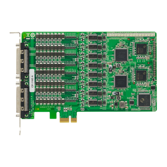
PCI Express Boards Product Specifications CP-116E-A Specifications Hardware Connector Female SCSI VHDCI68 Comm. Controller 16C550C Compatible Interface Bus Interface PCI-Express x 1 Number of Ports Max No. of Boards Signal RS-232 TxD, RxD, RTS, CTS, DTR, DSR, DCD, GND RS-422...
Need help?
Do you have a question about the CP-116E-A and is the answer not in the manual?
Questions and answers