
Related Manuals for Moxa Technologies WE-2100T Series


Summary of Contents for Moxa Technologies WE-2100T Series
- Page 1 WE-2100T Series User’s Manual Third Edition, June 2008 www.moxa.com/product © 2008 Moxa Inc., all rights reserved. Reproduction without permission is prohibited.
-
Page 2: Copyright Notice
WE-2100T Series User’s Manual The software described in this manual is furnished under a license agreement and may be used only in accordance with the terms of that agreement. Copyright Notice Copyright © 2008 Moxa Inc. All rights reserved. Reproduction without permission is prohibited. -
Page 3: Table Of Contents
Table of Contents Chapter 1 Introduction ....................1-1 Overview ..........................1-2 Package Checklist......................... 1-2 Product Features ........................1-2 Product Specifications ......................1-3 Chapter 2 Panel Layout and Pin Assignments ............2-1 Dimensions........................... 2-2 WE-2100T ........................2-2 WE-2100T-ST ......................2-3 Pin Assignments ........................2-4 WE-2100-ST LED Indicators .................... - Page 4 Network Settings> General Settings..................7-2 DNS Server 1 and 2 ...................... 7-2 Network Settings> Ethernet Settings..................7-3 IP Configuration ......................7-3 IP Address ........................7-4 Netmask........................7-4 Gateway........................7-4 Speed ..........................7-4 Network Settings> WLAN Settings> WLAN ..............7-5 IP Configuration ......................7-5 IP Address ........................
-
Page 5: Tcp Server Mode
Settings for RealCOM Mode....................8-3 TCP Alive Check Time ....................8-4 Max Connection ......................8-4 Delimiter 1 and 2 ......................8-5 Force Transmit......................8-5 Settings for RFC2217 Mode....................8-5 TCP Alive Check Time ....................8-6 TCP Port ........................8-6 Delimiter 1 and 2 ......................8-6 Force Transmit...................... - Page 6 To E-mail Address 1 to 4 ....................9-6 System Management> Auto Warning Settings> SNMP Trap ..........9-7 SNMP Trap Server IP or Domain Name ..............9-7 Trap Version ......................... 9-7 System Management> Maintenance> Console Settings............9-8 HTTP Console ......................9-8 HTTPS Console......................
- Page 7 Configuration........................12-6 Broadcast Search ......................12-7 Specify by IP Address ....................12-7 Unlock ........................12-7 Assign IP Address ...................... 12-8 Configure........................12-8 Upgrade Firmware...................... 12-9 Import and Export Configuration ................12-9 Monitor..........................12-10 Add Target........................ 12-10 Remove Target ......................12-11 Load Configured COM Port ..................
- Page 8 Example 1: Use Hardware Trigger, Get Model Name..........13-14 Example 2: Use Hardware Trigger, Change IP Address .......... 13-14 Example 3: Use Software Trigger, Get IP Mode............13-15 Example 4: Use SW Trigger, Change TCP Port Number......... 13-15 Appendix A Well Known Port Numbers ..............
-
Page 9: Chapter 1 Introduction
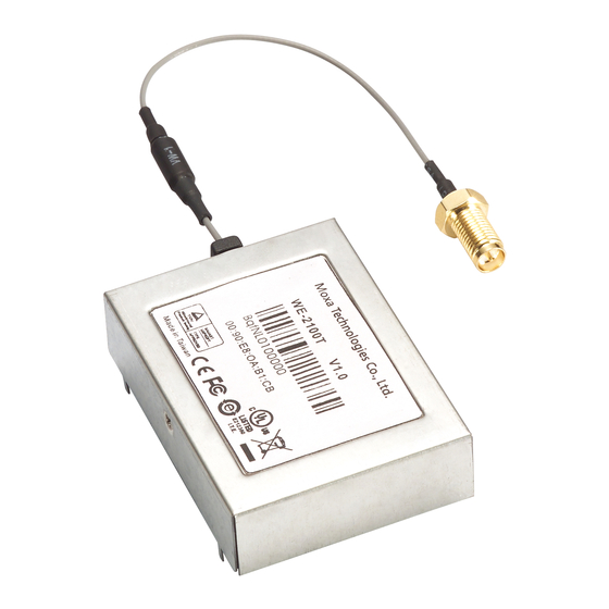
Introduction Chapter 1 The WE-2100T is a small embedded serial-to-WLAN module that gives your serial device the ability to connect to a wireless network. It comes with built-in TCP/IP and wireless security/authentication protocols for fast integration, saving you time and energy on programming. The following topics are covered in this chapter: Overview Package Checklist... -
Page 10: Overview
The development kit contains a development board, documents, sample code, cables, and accessories. Package Checklist 1 WE-2100T Series module (depending on which model you order) 1 WE-2100T-ST (the evaluation board ) WE-2100T Series Documentation & Software CD 1 power adaptor... -
Page 11: Product Specifications
WE-2100T Series User’s Manual Introduction Product Specifications WLAN Spread Spectrum Technology DSSS,CCK,OFDM Standards Compliance 802.11 a/b/g 5.15~5.25 GHz: 15 dBm@6 Mbps; 12 dBm@54 Mbps 5.725~5.825 GHz: 15 dBm@6 Mbps; 12 dBm@54 Mbps Tx Power 2.412~2.483 GHz: 17 dBm@6 Mbps; 15 dBm@54 Mbps 2.412~2.472 GHz:... - Page 12 WE-2100T Series User’s Manual Introduction Web console, serial console, Telnet console, Windows utility, serial Configuration command Power Requirements Power Input 3.3V ± 5% VDC Power 950 mA @ 3.3 VDC (max.) Consumption Environmental Operating 0 to 55 °C (32 to 131 °F), 5 to 95% RH...
-
Page 13: Panel Layout And Pin Assignments
Panel Layout and Pin Assignments Chapter 2 This chapter includes information about the panel layouts and pin assignments for WE-2100T. The layouts and reference circuit diagrams for the evaluation boards are also covered. The evaluation boards are used for evaluation and development of applications for WE-2100T. The following topics are covered in this chapter: Dimensions WE-2100T... -
Page 14: Dimensions
WE-2100T Series User’s Manual Panel Layout and Pin Assignments Dimensions WE-2100T Unit: mm... -
Page 15: We-2100T-St
WE-2100T Series User’s Manual Panel Layout and Pin Assignments WE-2100T-ST Unit: mm... -
Page 16: Pin Assignments
WE-2100T Series User’s Manual Panel Layout and Pin Assignments Pin Assignments Function Function 3.3V 3.3V 3.3V Console_TxD Console_RxD Console_RTS Console_CTS Console_DTR Console_DSR PIO0 Console_DCD PIO1 PIO4 (WLAN strength 1) PIO2 PIO5 (WLAN strength 2) PIO3 PIO6 (WLAN strength 3) Data_TxD... -
Page 17: We-2100-St Led Indicators
WE-2100T Series User’s Manual Panel Layout and Pin Assignments WE-2100-ST LED Indicators Type Color Status Meaning Power is off. Unit is booting or rebooting. IP error condition occurs. Ready Steady On Unit is functioning normally. Green Unit is responding to software Locate function. -
Page 18: Chapter 3 Getting Started
Getting Started Chapter 3 This chapter includes information about installing WE-2100T. The following topics are covered in this chapter: Wiring Requirements Installing onto the WE-2100T-ST Evaluation Board Circuit Pad Connecting to the Network Connecting the Power Connecting to a Serial Device DI/O Test Settings LED Circuit Diagram... -
Page 19: Wiring Requirements
WE-2100T Series User’s Manual Getting Started Wiring Requirements ATTENTION Before connecting the hardware, follow these important wiring safety precautions: Disconnect power source Do not install or wire this unit or any attached devices with the power connected. Disconnect the power before installation by removing the power cord before installing and/or wiring your unit. -
Page 20: Circuit Pad
WE-2100T Series User’s Manual Getting Started Circuit Pad The circuit pad on the evaluation board can be used to develop additional application circuits. -
Page 21: Connecting To The Network
WE-2100T Series User’s Manual Getting Started The bottom row of pins is for connecting a 5V power supply; the next row up is for connecting a 3.3V power supply. Digital I/O pins are located on the right side. The top row of pins is for grounding. -
Page 22: Di/O Test Settings
WE-2100T Series User’s Manual Getting Started DI/O Test Settings The WE-2100T includes 9 digital I/O channels. Each digital I/O channel is a GPIO (General Purpose I/O) channel that can be set to “digital output” or “digital input” mode by software. When developing your own applications, be aware of the voltage limits. -
Page 23: Led Circuit Diagram
WE-2100T Series User’s Manual Getting Started Use the web console to set the status of output channels. If you set channel 4’s status to “Low” and the others to “High,” the DO4 LED will glow and the other LEDs will remain dark. -
Page 24: Selecting An Operation Mode
Selecting an Operation Mode Chapter 4 In this section, we describe the available operation modes for the WE-2100T. There is a mode that relies on a driver installed on the host computer, and other modes that rely on TCP/IP socket programming concepts. -
Page 25: Overview
WE-2100T Series User’s Manual Selecting an Operation Mode Overview The WE-2100T connects serial devices to the wireless LAN. It has a built-in TCP/IP stack that saves you the effort of programming networking protocols. Simply select the proper operating mode to allow your computer to access, manage, and configure your serial device over the Internet. -
Page 26: Tcp Client Mode
WE-2100T Series User’s Manual Selecting an Operation Mode TCP Client Mode In TCP Client mode, the module actively establishes a TCP connection to a specific network host when data is received from the attached serial device. After the data has been... - Page 27 WE-2100T Series User’s Manual Selecting an Operation Mode ATTENTION Real COM drivers are installed and configured through the included Windows utility. Real COM mode allows you to continue using your serial communications software to access devices that are now attached to the WE-2100T module. On the host, the Real COM driver automatically intercepts data sent to the COM port, packs it into a TCP/IP packet, and redirects it to the network.
-
Page 28: Initial Ip Address Configuration
Initial IP Address Configuration Chapter 5 When setting up your WE-2100T module for the first time, the first thing you should do is configure the IP address. This chapter introduces the methods that can be used to configure the WE-2100T’s IP address. For more details about network settings, please refer to Chapter 7. This chapter includes the following sections: Selecting an IP Address or Configuration Assigning IP Address with Network Enabler Administration Suite... -
Page 29: Selecting An Ip Address Or Configuration
WE-2100T Series User’s Manual Initial IP Address Configuration Selecting an IP Address or Configuration For most applications, you will assign a fixed IP address to the module, which means that you set the IP address directly. However, for certain network environments, your module’s IP address will need to be assigned by a DHCP or BOOTP server. -
Page 30: Assigning Ip Address With Telnet Console
WE-2100T Series User’s Manual Initial IP Address Configuration Select a valid IP address for your WE-2100T module. Consult with your network administrator if necessary. Obtain the module’s MAC address from the label on the module. From the DOS prompt, execute the arp -s command with the desired IP address and the module’s MAC address, as in the following example:... - Page 31 WE-2100T Series User’s Manual Initial IP Address Configuration Select the terminal type and press ENTER. Select Network by pressing N or by using the cursor keys. Press ENTER after making the selection. Select Ethernet or WLAN and press ENTER.
- Page 32 WE-2100T Series User’s Manual Initial IP Address Configuration Use the cursor keys to navigate between the different fields. For IP address, Netmask, and Gateway, enter the desired values directly. For IP configuration and LAN speed, press ENTER to open a submenu and select between the available options.
-
Page 33: Assigning Ip Address With Serial Console
WE-2100T Series User’s Manual Initial IP Address Configuration Select System and then press ENTER. 10. Press Enter to restart the module. It will reboot with the new IP settings. Assigning IP Address with Serial Console You may use the module’s console port to configure the IP address. As soon as the connection is open, you will be presented with a text menu identical to the Telnet console. - Page 34 WE-2100T Series User’s Manual Initial IP Address Configuration In your terminal emulator program, set the terminal type to ANSI or VT100. If you select Dumb Terminal as the terminal type, some of the console functions may not work properly. After setting the terminal options, enter any character. The serial console will open and will be functionally identical to the Telnet console.
-
Page 35: Web Console: Basic Settings
Web Console: Basic Settings Chapter 6 The web console is the most user-friendly method available to configure the module. With a standard web browser, you have easy and intuitive access to all settings and options. In this chapter, we introduce the web console and go through the basic configuration options. The same configuration options are also available through the Telnet and serial console. -
Page 36: Overview
WE-2100T Series User’s Manual Web Console: Basic Settings Overview Web Browser Settings In order to use the web console, you will need to have cookies enabled for your browser. Please note that the web console uses cookies only for password transmission. -
Page 37: Navigating The Web Console
WE-2100T Series User’s Manual Web Console: Basic Settings Navigating the Web Console To open the web console, enter your module’s IP address in the website address line. If you are configuring the unit for the first time over an Ethernet cable, you will use the default LAN IP address, 192.168.126.254. -
Page 38: Basic Settings
WE-2100T Series User’s Manual Web Console: Basic Settings Basic Settings On the Basic Settings page, you can configure Server name, Server location, Time zone, Local time, and Time server. Server Name Default Options free text (e.g., “Server 1”) Description This is an optional free text field to help you differentiate one module from another. -
Page 39: Local Time
WE-2100T Series User’s Manual Web Console: Basic Settings Local Time Default Options Date (yy:mm:dd), Time (hh:mm:ss) Description The module has a built-in real-time clock that allows you to add time information to functions such as the automatic warning e-mail or SNMP trap. -
Page 40: Web Console: Network Settings
Web Console: Network Settings Chapter 7 The web console is the most user-friendly method available to configure the module. With a standard web browser, you have easy and intuitive access to all settings and options. In this chapter, we introduce the web console and go through the basic configuration options. The same configuration options are also available through the Telnet and serial console. -
Page 41: Overview
WE-2100T Series User’s Manual Web Console: Network Settings Overview This chapter explains how to configure all settings located under the Network Settings folder in the web console. Network Settings> General Settings On the General Settings page in the Network Settings folder, you can modify DNS server 1 and... -
Page 42: Network Settings> Ethernet Settings
WE-2100T Series User’s Manual Web Console: Network Settings Network Settings> Ethernet Settings On the Ethernet Settings page in the Network Settings folder, you can modify IP configuration, IP address, Netmask, Gateway, and Speed. You must assign a valid IP address to the WE-2100T before it will work in your network environment. -
Page 43: Ip Address
WE-2100T Series User’s Manual Web Console: Network Settings IP Address Default 192.168.126.254 Options IP address (e.g., “192.168.1.1”) Description This field is for the IP address that will be assigned to your WE-2100T module. An IP address is a number assigned to a network device (such as a computer) as a permanent address on the network. -
Page 44: Network Settings> Wlan Settings> Wlan
WE-2100T Series User’s Manual Web Console: Network Settings Network Settings> WLAN Settings> WLAN The WLAN page is located under WLAN Settings in the Network Settings folder. You can modify IP configuration, IP address, Netmask, and Gateway for your WLAN. The WE-2100T supports IEEE 802.11a/b/g wireless network interfaces. The supported IP configurations are static and dynamic (BOOTP , DHCP, or BOOTP+DHCP ). -
Page 45: Netmask
WE-2100T Series User’s Manual Web Console: Network Settings Netmask Default 255.255.255.0 Options Netmask setting (e.g., “255.255.0.0”) Description This field is for the subnet mask. A subnet mask represents all of the network hosts at one geographic location, in one building, or on the same local area network. -
Page 46: Network Settings> Wlan Settings> Profile
WE-2100T Series User’s Manual Web Console: Network Settings Network Settings> WLAN Settings> Profile The Profile page is located under WLAN Settings in the Network Settings folder. This is where you configure the WE-2100T for Ad-hoc or Infrastructure operation. Different settings are... -
Page 47: Network Type
WE-2100T Series User’s Manual Web Console: Network Settings Network Type Default Infrastructure Mode Options Infrastructure Mode, Ad-hoc Mode Description This field specifies whether the WE-2100T will operate in Ad-hoc or Infrastructure Mode. For all wireless networking devices, there are two possible modes for communication with another wireless device. -
Page 48: General Settings For Wlan Profile
WE-2100T Series User’s Manual Web Console: Network Settings General Settings for WLAN Profile The General page is opened through the Profile page, under WLAN Settings in the Network Settings folder. After selecting Ad-hoc or Infrastructure Mode, click General to view or modify the general properties for that profile. -
Page 49: Profile Name
WE-2100T Series User’s Manual Web Console: Network Settings In Infrastructure Mode On the General page, you can configure Profile name, Operation mode, and SSID. Additional settings are also available depending on whether you select Ad-hoc Mode or Infrastructure Mode. Profile Name... -
Page 50: Operation Mode
WE-2100T Series User’s Manual Web Console: Network Settings Operation Mode Default Auto Auto, 802.11a, 802.11b, 802.11g Options Description This field determines which wireless standard will be used by the selected profile. 802.11a, 802.11b, and 802.11g are supported. Auto: In Ad-hoc Mode, the WE-2100T will scan the 2.4G wireless band and will automatically select the appropriate wireless standard for communication with any other wireless devices that are detected. -
Page 51: Security Settings For Wlan Profile
WE-2100T Series User’s Manual Web Console: Network Settings Security Settings for WLAN Profile The Security page is opened through the Profile page, under WLAN Settings in the Network Settings folder. After selecting Ad-hoc or Infrastructure Mode, click Security to open the Security page for that profile. - Page 52 WE-2100T Series User’s Manual Web Console: Network Settings In Infrastructure Mode You will need to configure Authentication and Encryption. These settings must match the settings on the wireless device at the other end of the connection (such as the AP). Different settings and options are available depending on how Authentication and Encryption are configured.
-
Page 53: Authentication
WE-2100T Series User’s Manual Web Console: Network Settings Authentication Default Open System Options Open System, Shared Key, WPA, WPA-PSK, WPA2, WPA2-PSK Description This field specifies how wireless devices will be authenticated. Only authenticated devices will be allowed to communicate with the WE-2100T. If a RADIUS server is used, this setting must match the setting on the RADIUS server. -
Page 54: Encryption
WE-2100T Series User’s Manual Web Console: Network Settings Encryption Default Disable Disable, WEP, TKIP, AES-CCMP Options Description This field specifies the type of encryption to use during wireless communication. Different encryption methods are available depending on the Authentication setting. Also, each encryption method has its own set of parameters that may also require configuration. -
Page 55: Security Settings For Wep Encryption
WE-2100T Series User’s Manual Web Console: Network Settings Security Settings for WEP Encryption When Encryption is set to WEP on the Security page for the WLAN profile, you will be able to configure WEP key length, WEP key index, and WEP key source. Other settings will be displayed depending on how WEP key source is configured. -
Page 56: Wep Key Source
WE-2100T Series User’s Manual Web Console: Network Settings WEP Key Source Default Manual Manual, Generate WEP keys by passphrase Options Description This field specifies whether the WEP key will be generated manually or through a user-specified passphrase. A passphrase is equivalent to a free-text password that will be used to generate the WEP key. -
Page 57: Security Settings For Wpa, Wpa2
WE-2100T Series User’s Manual Web Console: Network Settings Security Settings for WPA, WPA2 When WPA or WPA2 is used for authentication, you will also need to configure EAP method in the Security settings for the WLAN profile. Other settings will also be displayed depending on how EAP method is configured. -
Page 58: Eap Method
WE-2100T Series User’s Manual Web Console: Network Settings EAP Method Default PEAP Options TLS, PEAP, TTLS, LEAP Description This field specifies the EAP method to use for authentication. Four methods are supported. TLS: Transport Layer Security (TLS) was created by Microsoft and accepted by the IETF as RFC 2716: PPP EAP TLS Authentication Protocol. -
Page 59: Anonymous Username
WE-2100T Series User’s Manual Web Console: Network Settings Anonymous Username Default free text (e.g., “Anyuser”) Options Description This field specifies the anonymous username to use when initiating authentication. After the RADIUS server has been verified by certificate, the true username and password will be used to complete the authentication process. -
Page 60: Network Settings> Advanced Settings
WE-2100T Series User’s Manual Web Console: Network Settings Network Settings> Advanced Settings On the Advanced Settings page in the Network Settings folder, you can modify Gratuitous ARP, Auto report to, Auto report period, and Active interface. Gratuitous ARP Default Disabled... -
Page 61: Auto Report Period
WE-2100T Series User’s Manual Web Console: Network Settings Auto Report Period Default Options 0 to 99 Description This field specifies how often the WE-2100T sends IP address reports. Active Interface Default Auto Detect Options Auto Detect, Select by DI8, Force Wired Ethernet, Force Wireless LAN... -
Page 62: Web Console: Serial Port Settings
Web Console: Serial Port Settings Chapter 8 The web console is the most user-friendly method available to configure the module. With a standard web browser, you have easy and intuitive access to all settings and options. In this chapter, we introduce the web console and go through the basic configuration options. The same configuration options are also available through the Telnet and serial console. -
Page 63: Overview
WE-2100T Series User’s Manual Web Console: Serial Port Settings Overview This chapter explains how to configure all settings located under the Serial Port Settings folder in the web console. Serial Port Settings> Port 1> Operation Modes The Operation Modes page is where you configure the serial port’s operation mode and related settings. -
Page 64: Mode
WE-2100T Series User’s Manual Web Console: Serial Port Settings Mode Default (depends on Application) Options RealCOM, RFC2217, TCP Server, TCP Client, UDP Along with Application, this field specifies the serial port’s operation mode, or Description how it will interact with network devices. Depending on how Application is configured, different options are available for Mode. -
Page 65: Tcp Alive Check Time
WE-2100T Series User’s Manual Web Console: Serial Port Settings TCP Alive Check Time Default 7 min Options 0 to 99 min Description This field specifies how long the module will wait for a response to “keep alive” packets before closing the TCP connection. The module checks connection status by sending periodic “keep alive”... -
Page 66: Delimiter 1 And 2
WE-2100T Series User’s Manual Web Console: Serial Port Settings Delimiter 1 and 2 Default Disabled Options Disabled, Enabled, 00 to FF Description These fields are used to define special delimiter character(s) for data packing. Enable Delimiter 1 to control data packing with a single character; enable both Delimiter 1 and 2 to control data packing with two characters received in sequence. -
Page 67: Tcp Alive Check Time
WE-2100T Series User’s Manual Web Console: Serial Port Settings When Mode is set to RFC2217 on the Operation Modes page, you will be able to configure additional settings such as TCP alive check time, TCP port, and Delimiter 1 and 2. -
Page 68: Force Transmit
WE-2100T Series User’s Manual Web Console: Serial Port Settings Force Transmit Default 0 ms Options 0 to 65535 Description This field controls data packing by the amount of time that elapses between bits of data. 0: If serial data is not received, the module will wait indefinitely for additional data. -
Page 69: Tcp Alive Check Time
WE-2100T Series User’s Manual Web Console: Serial Port Settings TCP Alive Check Time Default 7 min Options 0 to 99 min Description This field specifies how long the module will wait for a response to “keep alive” packets before closing the TCP connection. The module checks connection status by sending periodic “keep alive”... -
Page 70: Delimiter 1 And 2
WE-2100T Series User’s Manual Web Console: Serial Port Settings Delimiter 1 and 2 Default Disabled Options Disabled, Enabled, 00 to FF Description These fields are used to define special delimiter character(s) for data packing. Enable Delimiter 1 to control data packing with a single character; enable both Delimiter 1 and 2 to control data packing with two characters received in sequence. -
Page 71: Settings For Tcp Client Mode
WE-2100T Series User’s Manual Web Console: Serial Port Settings Settings for TCP Client Mode When Mode is set to TCP Client on the Operation Modes page, you will be able to configure additional settings such as TCP alive check time, Inactivity time, and Connection control. -
Page 72: Inactivity Time
WE-2100T Series User’s Manual Web Console: Serial Port Settings Inactivity Time Default 0 ms Options 0 to 65535 ms Description This field specifies the time limit for keeping the connection open if no data flows to or from the serial device. -
Page 73: Delimiter 1 And 2
WE-2100T Series User’s Manual Web Console: Serial Port Settings Delimiter 1 and 2 Default Disabled Options Disabled, Enabled, 00 to FF Description These fields are used to define special delimiter character(s) for data packing. Enable Delimiter 1 to control data packing with a single character; enable both Delimiter 1 and 2 to control data packing with two characters received in sequence. -
Page 74: Settings For Udp Mode
WE-2100T Series User’s Manual Web Console: Serial Port Settings Settings for UDP Mode When Mode is set to UDP on the Operation Modes page, you will be able to configure additional settings such as Destination address 1 through 4, Local listen port, and Delimiter 1 and 2. -
Page 75: Delimiter 1 And 2
WE-2100T Series User’s Manual Web Console: Serial Port Settings Delimiter 1 and 2 Default Disabled Options Disabled, Enabled, 00 to FF Description These fields are used to define special delimiter character(s) for data packing. Enable Delimiter 1 to control data packing with a single character; enable both Delimiter 1 and 2 to control data packing with two characters received in sequence. -
Page 76: Port Alias
WE-2100T Series User’s Manual Web Console: Serial Port Settings The Communication Parameters page is where serial communication settings are specified, such as Baud rate, Data bits, and Stop bits. Port Alias Default Options free text (e.g., “Secondary console connection”) This is an optional free text field to help you differentiate one serial port from Description another. -
Page 77: Fifo
WE-2100T Series User’s Manual Web Console: Serial Port Settings FIFO Default Enable Options Enable, Disable Description This field specifies whether the serial port will use the built-in FIFO. A 128-byte FIFO is provided to each serial port for both Tx and Rx directions. To prevent data loss during serial communication, this should be set to Disabled if the attached serial device does not have a FIFO. -
Page 78: Web Console: System Management
Web Console: System Management Chapter 9 The web console is the most user-friendly method available to configure the module. With a standard web browser, you have easy and intuitive access to all settings and options. In this chapter, we introduce the web console and go through the basic configuration options. The same configuration options are also available through the Telnet and serial console. -
Page 79: Overview
WE-2100T Series User’s Manual Web Console: System Management Overview This chapter explains how to configure all settings located under the System Management folder in the web console. System Management> Misc. Network Settings> Accessible IP List The Accessible IP List page is located under Misc. Network Settings in the System Management folder. -
Page 80: System Management> Misc. Network Settings> Snmp Agent Settings
WE-2100T Series User’s Manual Web Console: System Management System Management> Misc. Network Settings> SNMP Agent Settings The SNMP Agent page is located under Misc. Network Settings in the System Management folder. This page is used to configure the SNMP Agent on the WE-2100T. -
Page 81: System Management> Auto Warning Settings> Event Settings
WE-2100T Series User’s Manual Web Console: System Management System Management> Auto Warning Settings> Event Settings The Event Settings page is located under Auto Warning Settings in the System Management folder. This is where you specify how the WE-2100T will notify you of system and configuration events. -
Page 82: System Management> Auto Warning Settings> E-Mail Alert
WE-2100T Series User’s Manual Web Console: System Management The Serial Event Settings page is located under Auto Warning Settings in the System Management folder. This is where you specify how the WE-2100T will notify you of DCD and DSR events for each serial port. Mail refers to sending an e-mail to a specified address. Trap refers to sending an SNMP trap. -
Page 83: From E-Mail Address
WE-2100T Series User’s Manual Web Console: System Management Default Options free text (e.g., “192.168.3.3”) Description This field specifies the IP address of the mail server that will be used when sending automatic warning e-mails. If the mail server requires authentication, select “My server requires authentication”... -
Page 84: System Management> Auto Warning Settings> Snmp Trap
WE-2100T Series User’s Manual Web Console: System Management System Management> Auto Warning Settings> SNMP Trap The SNMP Trap page is located under Auto Warning Settings in the System Management folder. This is where you specify the SNMP trap settings to use for automatic notification of system and serial port events. -
Page 85: System Management> Maintenance> Console Settings
WE-2100T Series User’s Manual Web Console: System Management System Management> Maintenance> Console Settings The Console Settings page is located under Maintenance in the System Management folder. This is where you enable or disable access to the various module configuration consoles. You may modify HTTP console, HTTPS console, Telnet console, and SSH console. -
Page 86: System Management> Maintenance> Ping
WE-2100T Series User’s Manual Web Console: System Management System Management> Maintenance> Ping The Ping page is located under Maintenance in the System Management folder. It provides a convenient way to test an Ethernet connection or verify an IP address. Enter the IP address or... -
Page 87: System Management> Maintenance> Firmware Upgrade
WE-2100T Series User’s Manual Web Console: System Management System Management> Maintenance> Firmware Upgrade The Firmware Upgrade page is located under Maintenance in the System Management folder. This is where you can update the WE-2100T's firmware. After obtaining the latest firmware from www.moxa.com, select or browse for the firmware file in the Select firmware file field. -
Page 88: System Management> Maintenance> Configuration Import
WE-2100T Series User’s Manual Web Console: System Management System Management> Maintenance> Configuration Import The Configuration Import page is located under Maintenance in the System Management folder. This is where you can load a previously saved or exported configuration. Select or browse for the configuration file in the Select configuration file field. -
Page 89: System Management> Maintenance> Configuration Export
WE-2100T Series User’s Manual Web Console: System Management System Management> Maintenance> Configuration Export The Configuration Export page is located under Maintenance in the System Management folder. This is where you can save the module's current configuration to a file on the local host. -
Page 90: System Management> Maintenance> Load Factory Default
WE-2100T Series User’s Manual Web Console: System Management System Management> Maintenance> Load Factory Default The Load Factory Default page is located under Maintenance in the System Management folder. Click Submit to reset all settings to the factory defaults. You can preserve the module's existing IP settings (i.e., IP address, netmask, gateway, WLAN profile, and all certificates) by... -
Page 91: System Management> Maintenance> Change Password
WE-2100T Series User’s Manual Web Console: System Management System Management> Maintenance> Change Password The Change Password page is located under Maintenance in the System Management folder. To change the password, first enter the old password in the Old password field. Leave this blank if the module is not currently password-protected. -
Page 92: System Management> System Settings> Serial Command Mode
WE-2100T Series User’s Manual Web Console: System Management System Management> System Settings> Serial Command Mode The Serial Command Mode page is located under System Settings in the System Management folder. This is where you specify how Serial Command Mode will be enabled. For details on Serial Command Mode, please refer to Chapter 13. -
Page 93: System Management> System Settings> Digital Io
WE-2100T Series User’s Manual Web Console: System Management System Management> System Settings> Digital IO The Digital IO page is located under System Settings in the System Management folder. This is where you configure the 9 built-in DIO channels. DIO0 through DIO8... -
Page 94: Tcp Port
WE-2100T Series User’s Manual Web Console: System Management Default Enable WLAN LED Options Enable/Disable WLAN LED Description This specifies whether the WLAN LEDs will be used. If enabled, DIO 4 through 8 will be reserved for use as WLAN LEDs. Manual settings for those DIO channels will thus be ignored. -
Page 95: System Management> Certificate> Ethernet Ssl Certificate Import
WE-2100T Series User’s Manual Web Console: System Management System Management> Certificate> Ethernet SSL Certificate Import The Ethernet SSL Certificate Import page is located under Certificate in the System Management folder. This is where you can load the Ethernet SSL certificate. Select or browse for the certificate file in the Select SSL certificate/key file field. -
Page 96: System Management> Certificate> Wlan Ssl Certificate Import
WE-2100T Series User’s Manual Web Console: System Management System Management> Certificate> WLAN SSL Certificate Import The WLAN SSL Certificate Import page is located under Certificate in the System Management folder. By default, the WLAN SSL certificate is automatically generated by the WE-2100T based on the IP address of the wireless interface. -
Page 97: System Management> Certificate> Wpa Server Certificate Import
WE-2100T Series User’s Manual Web Console: System Management System Management> Certificate> WPA Server Certificate Import The WPA Server Certificate Import page is located under Certificate in the System Management folder. This is where you can load the WPA server certificate. Select or browse for the certificate file in the Select WPA server certificate file field. -
Page 98: System Management> Certificate> Wpa User Certificate Import
WE-2100T Series User’s Manual Web Console: System Management System Management> Certificate> WPA User Certificate Import The WPA User Certificate Import page is located under Certificate in the System Management folder. This is where you can load the WPA user certificate. Select or browse for the certificate file in the Select WPA user certificate file field. -
Page 99: System Management> Certificate> Wpa User Key Import
WE-2100T Series User’s Manual Web Console: System Management System Management> Certificate> WPA User Key Import The WPA User Key Import page is located under Certificate in the System Management folder. This is where you can load the WPA user key. Select or browse for the user private key file in the Select WPA user privacy key file field and enter the Password for the private key. - Page 100 WE-2100T Series User’s Manual Web Console: System Management WE-2100T. When you click Submit, any certificate or key that has been set to “Delete” will be deleted from the module. 9-23...
-
Page 101: Web Console: System Monitoring
Web Console: System Monitoring Chapter 10 The web console is the most user-friendly method available to configure the module. With a standard web browser, you have easy and intuitive access to all settings and options. In this chapter, we introduce the web console and go through the basic configuration options. The same configuration options are also available through the Telnet and serial console. -
Page 102: Overview
WE-2100T Series User’s Manual Web Console: System Monitoring Overview This chapter explains how to use the System Monitoring functions on the web console. These functions allow you to monitor many different aspects of operation. System Monitoring> Serial Status> Serial to Network... -
Page 103: System Monitoring> Serial Status> Serial Port Error Count
WE-2100T Series User’s Manual Web Console: System Monitoring RxTotalCnt: number of Rx packets since the module was powered on DSR: status of DSR signal DTR: status of DTR signal RTS: status of RTS signal CTS: status of CTS signal DCD: status of DCD signal System Monitoring>... -
Page 104: System Monitoring> System Status> Network Connections
WE-2100T Series User’s Manual Web Console: System Monitoring System Monitoring> System Status> Network Connections The Network Connections page is located under System Status in the System Monitoring folder. On this page, you can view the current status of any network connection to the WE-2100T. -
Page 105: System Monitoring> System Status> Wlan Status
WE-2100T Series User’s Manual Web Console: System Monitoring System Monitoring> System Status> WLAN Status The WLAN Status page is located under System Status in the System Monitoring folder. This is where you can view the current WLAN settings and status. - Page 106 WE-2100T Series User’s Manual Web Console: System Monitoring The goal of a WLAN site survey is to determine the number and placement of access points to provide enough coverage to the facility. For most implementations, "enough coverage" means that the data rate at all locations does not fall below a certain threshold. For most wireless sites, it is necessary to perform a WLAN site survey before access point installation in order to determine the behavior of radio waves at the site.
-
Page 107: System Monitoring> System Status> Digital Io State
WE-2100T Series User’s Manual Web Console: System Monitoring System Monitoring> System Status> Digital IO State The Digital IO State page is located under System Status in the System Monitoring folder. This is where you can view the current settings and status for all DIO channels. -
Page 108: Web Console: Save And Restart
Web Console: Save and Restart Chapter 11 The web console is the most user-friendly method available to configure the module. With a standard web browser, you have easy and intuitive access to all settings and options. In this chapter, we introduce the web console and go through the basic configuration options. The same configuration options are also available through the Telnet and serial console. -
Page 109: Overview
WE-2100T Series User’s Manual Web Console: Save and Restart Overview This chapter explains how to use save your configuration changes and restart the WE-2100T using the web console. Configuration changes will not be effective until they are saved and the WE-2100T is rebooted. -
Page 110: Restart> Restart Ports
WE-2100T Series User’s Manual Web Console: Save and Restart Restart> Restart Ports The Restart Ports page is located in the Restart folder. Select port 1 and click Submit to restart the serial port. 11-3... -
Page 111: Using Network Enabler Administrator
Using Network Enabler Administrator Chapter 12 Network Enabler Administrator is a useful Windows utility that can be used to configure your WE-2100T. In this chapter, we will discuss how to use Network Enabler Administrator. This chapter includes the following sections: Overview Installation Navigation... -
Page 112: Overview
WE-2100T Series User’s Manual Using Network Enabler Administrator Overview Network Enabler Administrator provides everything you need to remotely manage, monitor, and modify your WE-2100T—hassle free. Installation Open the setup program and click Yes to proceed. A Welcome message will appear. Click Next to proceed. - Page 113 WE-2100T Series User’s Manual Using Network Enabler Administrator Verify that you are ready to install and click Install to proceed. When the installation is complete, click Finish to exit the wizard. 12-3...
-
Page 114: Navigation
WE-2100T Series User’s Manual Using Network Enabler Administrator Navigation Network Enabler Administrator is designed to make it easy to configure, monitor, or manage any WE-2100T module on your network. The interface is organized into four areas as follows: The top section is the menu area. Functions and commands can be selected here. - Page 115 WE-2100T Series User’s Manual Using Network Enabler Administrator Opening the Function Context Menu Each function has its own function context menu where specific commands are selected. A function’s context menu is opened by right-clicking the function in the function panel or by right-clicking the target module in the module list.
-
Page 116: Configuration
WE-2100T Series User’s Manual Using Network Enabler Administrator Configuration Within the Configuration function are commands to configure your module, import and export its configuration, and update its firmware. The Configuration context menu is shown below: Modules may be password-protected to prevent unauthorized configuration changes. A module’s password status will be shown in the target module list. -
Page 117: Broadcast Search
WE-2100T Series User’s Manual Using Network Enabler Administrator Broadcast Search Description This identifies all modules on the LAN and places them in the target module list for the Configuration function. Since this search is based on MAC address, rather than IP address, it will be able to find units that are not on the same subnet as your PC. -
Page 118: Assign Ip Address
WE-2100T Series User’s Manual Using Network Enabler Administrator Assign IP Address Description This allows you to set the target module’s IP address quickly, instead of digging through pages of configuration parameters. Configure Description This opens the target module’s configuration window. In the configuration window, tabs are used to navigate between the different settings. -
Page 119: Upgrade Firmware
WE-2100T Series User’s Manual Using Network Enabler Administrator ATTENTION You can configure multiple units simultaneously if the units are all the same model. Simply hold down the CTRL or SHIFT key when selecting the target modules. Upgrade Firmware This allows you to upload new firmware to the target module. You will be Description prompted to indicate where the firmware file is located. -
Page 120: Monitor
WE-2100T Series User’s Manual Using Network Enabler Administrator Monitor The Monitor function is used for live monitoring of your module over the network. Different parameters and events may be monitored, and you can receive pop-up warnings for certain events. The Monitor context menu is shown below:... -
Page 121: Remove Target
WE-2100T Series User’s Manual Using Network Enabler Administrator Remove Target Description This removes a module from the Monitor list. Load Configured COM Port If any COM ports are being mapped to modules over the network, this Description command will add those modules to the Monitor list. (COM ports can be mapped over the network to a serial port on the WE-2100T that is operating in RealCOM mode.) -
Page 122: Stop
WE-2100T Series User’s Manual Using Network Enabler Administrator Description This activates live monitoring. All modules on the Monitor list will be monitored live, as indicated by “Running” in the header. If alarms are enabled through the Setting command, a notification will appear when a monitored unit goes off-line. -
Page 123: Port Monitor
WE-2100T Series User’s Manual Using Network Enabler Administrator Port Monitor The Port Monitor function is identical to the Monitor function, but with many additional items that can be monitored, as shown below. In addition, each serial port will be listed as a separate item on the Port Monitor list and can be selected or deselected for monitoring. -
Page 124: Com Mapping
WE-2100T Series User’s Manual Using Network Enabler Administrator COM Mapping The COM Mapping function is used to configure the Real COM drivers, which are automatically installed with Network Enabler Administrator. The Real COM drivers map COM ports over the network to serial ports on WE-2100T modules. This allows a local application to use COM5, for example, to communicate with a device attached to the module. -
Page 125: Add Target
WE-2100T Series User’s Manual Using Network Enabler Administrator Add Target Description This places modules on the module list for COM mapping. You may need to click Rescan to search the network for available modules. You can also select Input manually to enter a specific IP address and model. - Page 126 WE-2100T Series User’s Manual Using Network Enabler Administrator ATTENTION You can map multiple COM ports in one step by holding down the CTRL or SHIFT key when selecting the target serial ports. Basic Settings In the Basic Settings tab, the COM Number parameter selects the COM port that will be mapped to the device port.
-
Page 127: Advanced Settings
WE-2100T Series User’s Manual Using Network Enabler Administrator Advanced Settings In the Advanced Settings tab, you may configure how serial data is transmitted from the PC to the WE-2100T. Tx Mode Hi-Performance is the default for Tx mode. After the driver sends data to the module, the driver immediately issues a “Tx Empty”... -
Page 128: Apply And Discard Change
WE-2100T Series User’s Manual Using Network Enabler Administrator Apply and Discard Change Description This specifies whether or not to update the Real COM drivers with the changes made through the COM Settings command. If changes are discarded, the Real COM drivers will retain their original settings. If the changes are applied, the Real COM drivers will be updated with the new settings and mappings. -
Page 129: Settings
WE-2100T Series User’s Manual Using Network Enabler Administrator Settings Description This designates the TCP port number that the module is using to send IP address reports. This must correspond with the settings on the module. Description This activates monitoring for IP address reports. Network Enabler Administrator will begin listening for reports using the port number specified by the Settings command. -
Page 130: Serial Command Mode
Serial Command Mode Chapter 13 Serial Command Mode allows configuration of the module through serial commands received directly through the serial port. This chapter includes the following sections: Overview Serial Command Format Command Structure Reply Structure Command Set Operation Flow Chart Configuring Trigger Type Entering Serial Command Mode Determining the Active Mode... -
Page 131: Overview
WE-2100T Series User’s Manual Serial Command Mode Overview In Serial Command Mode, the module’s parameters are retrieved or configured using specially parsed commands that are sent through the serial port. Device manufacturers can take advantage of Serial Command Mode to add local configuration capability to their products. For example, a card reader’s number pad could be used to configure the card reader's IP address, netmask, and... -
Page 132: Command Set
WE-2100T Series User’s Manual Serial Command Mode Descriptor Bytes Character Comments Tail carriage return character, no line feed For example, to indicate that the TCP server port number has been written successfully, the module would return "<YTL" followed by CR. Available OP codes and parameters are described in the next section. - Page 133 WE-2100T Series User’s Manual Serial Command Mode OP Code Parameter Comments xxx.xxx.xxx.xxx accessible IP address 05 (e.g., 192.168.127.1) xxx.xxx.xxx.xxx accessible IP address 06 (e.g., 192.168.127.1) xxx.xxx.xxx.xxx accessible IP address 07 (e.g., 192.168.127.1) xxx.xxx.xxx.xxx accessible IP address 08 (e.g., 192.168.127.1) xxx.xxx.xxx.xxx accessible IP address 09 (e.g., 192.168.127.1)
-
Page 134: Operation Mode Commands
WE-2100T Series User’s Manual Serial Command Mode OP Code Parameter Comments xxx.xxx.xxx.xxx accessible IP netmask 11 (e.g., 255.255.255.0) xxx.xxx.xxx.xxx accessible IP netmask 12 (e.g., 255.255.255.0) xxx.xxx.xxx.xxx accessible IP netmask 13 (e.g., 255.255.255.0) xxx.xxx.xxx.xxx accessible IP netmask 14 (e.g., 255.255.255.0) xxx.xxx.xxx.xxx accessible IP netmask 15 (e.g., 255.255.255.0) -
Page 135: Real Com Mode Commands
WE-2100T Series User’s Manual Serial Command Mode Real COM Mode Commands OP Code Parameter Comments 1 – 4 max. number of connections 0 – 99 (minutes) TCP alive check time 0: no delimiter 1: enable 1-character delimiter number of characters to use as delimiter... -
Page 136: Udp Mode Commands
WE-2100T Series User’s Manual Serial Command Mode UDP Mode Commands OP Code Parameter Comments 0 – 65535 local listen port xxx.xxx.xxx.xxx destination IP address 1, begin range (e.g., 192.168.1.1) xxx.xxx.xxx.xxx destination IP address 2, begin range (e.g., 192.168.1.1) xxx.xxx.xxx.xxx destination IP address 3, begin range (e.g., 192.168.1.1) -
Page 137: Digital Io Commands
WE-2100T Series User’s Manual Serial Command Mode Digital IO Commands OP Code Parameter Comments bytes 1 and 2 (DIO #) 00: DIO 0 00: DIO 1 00: DIO 2 set DIO mode 03: DIO 3 (e.g., “000” sets DIO 0 to input mode) -
Page 138: Operation Flow Chart
WE-2100T Series User’s Manual Serial Command Mode Operation Flow Chart ATTENTION This flowchart represents a continual process. You can start trace out a logical flow by starting anywhere on the chart. Diamonds represent decision points. Only one path leading out of any diamond can be followed. -
Page 139: Using Network Enabler Administrator
WE-2100T Series User’s Manual Serial Command Mode ATTENTION The default trigger type is hardware (DIO 0). Only one type of trigger may be active at a time; hardware and software trigger may not be used at the same time. Using Network Enabler Administrator To use Network Enabler Administrator to configure the trigger type, you will need to find the module and open its configuration window. -
Page 140: Using Telnet Console
WE-2100T Series User’s Manual Serial Command Mode Using Telnet Console Please refer to Chapter 5 for information on opening the Telnet console. The Serial Command Mode trigger is configured under System > System > Sercmd. For the changes to take effect, you will need to go back to the main menu, save the configuration, and restart the module. -
Page 141: Software Trigger
WE-2100T Series User’s Manual Serial Command Mode Using Web Console Please refer to Chapter 6 for information on opening the web console. The Serial Command Mode page is located under System Settings in the System Management folder. Modify the settings as needed, and then click Submit. Remember that you will need to save the configuration and restart the module for any changes to effect. -
Page 142: Determining The Active Mode
WE-2100T Series User’s Manual Serial Command Mode which can be obtained using Network Enabler Administrator, the web console, or the Telnet console. Exiting Serial Command Mode After the module has entered Serial Command Mode, there are three ways to exit. -
Page 143: Serial Command Examples
WE-2100T Series User’s Manual Serial Command Mode Serial Command Examples For the following examples, the module should be installed onto the evaluation board, and the evaluation board’s serial port (P0) should be connected to a COM port on your PC. -
Page 144: Example 3: Use Software Trigger, Get Ip Mode
WE-2100T Series User’s Manual Serial Command Mode STEP 8: Type “>WBR2” in HyperTerminal and press ENTER, which saves changes and restarts the module. STEP 9: Repeat STEP 1 to STEP 5 to re-enter Serial Command Mode. STEP 10: Type “>RNP”... - Page 145 WE-2100T Series User’s Manual Serial Command Mode STEP 10: Type “>RTL” in HyperTerminal and press ENTER, which requests the TCP server’s TCP port number. STEP 11: HyperTerminal displays “<YTL4001”, indicating that the TCP server’s TCP port number is 4001. STEP 12: Type “>WBR1”...
-
Page 146: Appendix A Well Known Port Numbers
Well Known Port Numbers Appendix A This appendix is included for your reference. Listed below are Well Known Port Numbers that may cause network problems if you configure WE-2100T for the same port. Refer to RFC 1700 for Well Know Port Numbers or refer to the following introduction from IANA. The port numbers are divided into three ranges: the Well Known Ports, the Registered Ports, and the Dynamic and/or Private Ports. - Page 147 WE-2100T Series User’s Manual Well Known Port Numbers TCP Socket Application Service Whois (nickname) (Login Host Protocol) (Login) Domain Name Server (domain) Finger protocol (Finger) TCP Socket Application Service World Wibe Web HTTP Netword news Transfer Protocol (NNTP) Network Time Protocol 160 –...
- Page 148 NECI Library Appendix B The NECI (Network Enabler Configuration Interface) library is a set of APIs that run in Windows to search, locate, and configure the WE-2100T over the network. The library supports Windows 95, 98, ME, NT, 2000, XP, and Vista. You can find the library on the Document and Software CD in the \NECI_ LIB\ folder.
- Page 149 DIO Commands Appendix C In this appendix, we present the DIO commands used to access the Digital I/O status of the WE-2100T from an Ethernet network. The Digital I/O status can be accessed by a specific TCP port (default 5001) on the WE-2100T. Command Packet Format Length (Bytes) 1 –...
- Page 150 WE-2100T Series User’s Manual DIO Commands Data Structure Definition: C code example: //define DIO Header format typedef struct _DIO_Header_Struct { char command; char version; /* This specification is version 2 */ char status; char length; } DIOHeaderStruct, *pDIOHeaderStruct; //define DIO Packet format...
- Page 151 WE-2100T Series User’s Manual DIO Commands Command Status: doesn’t matter Length of data: 3(hex); represents three bytes. data[0]: The number of the DIO you wish to access. data[1]: DIO mode(hex), 0 for IN, 1 for OUT data[2]: DIO status(hex), 0 for LOW, 1 for HIGH Return: Command Status: Check the Command Status code on the previous page.
- Page 152 WE-2100T Series User’s Manual DIO Commands packet.header.command = 5; // Read Multiple DIO Commands packet.header.version = 2; // DIO protocol command version packet.header.length = 2; // data length packet.data[0] = start; // start of the DIO number packet.data[1] = end;...
- Page 153 WE-2100T Series User’s Manual DIO Commands //Process the returned data here A utility for testing DIO access commands is provided on the Document and Software CD-ROM.
-
Page 154: Rfc1213 Mib-Ii Supported Snmp Variables
SNMP Agent with MIB II & RS-232 Appendix D Like Group The WE-2100T has built-in SNMP (Simple Network Management Protocol) agent software. It supports SNMP Trap, RFC1317 RS-232-like groups, and RFC 1213 MIB-II. The following table lists the standard MIB-II groups, as well as the variable implementations for WE-2100T. RFC1213 MIB-II supported SNMP variables System MIB Interfaces MIB... - Page 155 WE-2100T Series User’s Manual SNMP Agent, MIB II, RS-232-Like Groups System MIB Interfaces MIB IP MIB ICMP MIB ifOutErrors ipAdEntIfIndex IcmpOutEchoReps ifOutQLen ipAdEntNetMask IcmpOutTimestamps ifSpecific ipAdEntBcastAddr IcmpOutTimestampReps ipAdEntReasmMaxSize IcmpOutAddrMasks IpNetToMediaIfIndex IcmpOutAddrMaskReps IpNetToMediaPhysAddress IpNetToMediaNetAddress IpNetToMediaType IpRoutingDiscards UDP MIB TCP MIB SNMP MIB...
-
Page 156: Appendix Eip Address Report Protocol
IP Address Report Protocol Appendix E When the WE-2100T module is configured to obtain its IP address automatically as a DHCP client, it sends a DHCP request over the network to find the DHCP server. The DHCP server will then send an available IP address to the module with an expiration time. The module will use this IP address until the expiration time has been reached. -
Page 157: Hardware And Ap Id
WE-2100T Series User’s Manual IP Address Report Protocol Header Header Item (Item (Item ID) Length) (varies) server name (text string) hardware ID (little endian, see table below) MAC address (00-90-E8-01-02-03 would be sent in sequence as 0x00, 0x90, 0xE8, 0x01, 0x02, 0x03) -
Page 158: Example
WE-2100T Series User’s Manual IP Address Report Protocol Example The following example shows the first 22 bytes of a typical IP address report: hardware report header server name MAC address “Moxa” “TEST” 0x4119 00-90-E8-01 -02-03 HEX 4D 4F 58 41 01 04 54 45 53 54 02 02 19 41 03 06 00 90 E8 01 02 03 ASCII “M”...
Need help?
Do you have a question about the WE-2100T Series and is the answer not in the manual?
Questions and answers