GeoVision GV-BX110D User Manual
Gv-ipcam h.264
Hide thumbs
Also See for GV-BX110D:
- User manual (393 pages) ,
- Quick start manual (130 pages) ,
- Quick start manual (85 pages)

Related Manuals for GeoVision GV-BX110D


Summary of Contents for GeoVision GV-BX110D
- Page 1 GV-IPCam H.264 User's Manual Before attempting to connect or operate this product, ICH264TIV114-A please read these instructions carefully and save this manual for future use.
- Page 2 GeoVision. Every effort has been made to ensure that the information in this manual is accurate. GeoVision, Inc. makes no expressed or implied warranty of any kind and assumes no responsibility for errors or omissions. No liability is assumed for incidental or consequential damages arising from the use of the information or products contained herein.
- Page 3 Safety Notice FCC Compliance for GV-CBW120/220 This device complies with Part 15 of the FCC Rules. Operation is subject to the following two conditions: (1) this device may not cause harmful interference and (2) this device must accept any interference received, including interference that may cause undesired operation of the device.
- Page 4 Appendix I Supported Firmware for Flash Memory. To upgrade your camera to firmware V1.09 or later, it is required to use GV IP Device Utility V8.5.3.0. Firmware Model Model Number Version Fixed Lens GV-BX110D V1.08 Varifocal Lens GV-BX120D Varifocal Lens GV-BX130D-0 Varifocal Lens GV-BX130D-1...
- Page 5 Firmware Model Model Number Version GV-BX120D-E IR Arctic Box GV-BX220D-E Varifocal Lens V1.14 Camera GV-BX320D-E GV-BX520D-E GV-MFD110 V1.08 GV-MFD120 Mini Fixed GV-MFD130 Fixed Lens V1.14 Dome GV-MFD220 GV-MFD320 GV-MFD520 GV-MDR120 Mini Fixed GV-MDR220 Fixed Lens V1.14 Rugged Dome GV-MDR320 GV-MDR520 GV-BL110D Varifocal Lens V1.08...
- Page 6 Firmware Model Model Number Version GV-VD120D (IK10+, Transparent Cover) GV-VD121D (IK10+, Smoked Cover) GV-VD122D (IK7, Transparent Cover) GV-VD123D (IK7, Smoked Cover) GV-VD220D (IK10+, Transparent Cover) GV-VD221D Vandal Proof (IK10+, Smoked Cover) Varifocal Lens V1.14 IP Dome GV-VD222D (IK7, Transparent Cover) GV-VD223D (IK7, Smoked Cover) GV-VD320D...
- Page 7 Firmware Model Model Number Version GV-CB120 GV-CB220 Cube Camera Fixed Lens V1.14 GV-CBW120 GV-CBW220 GV-CA120 Advanced GV-CA220 Fixed Lens Upcoming Cube Camera GV-CAW120 GV-CAW220...
-
Page 8: Table Of Contents
2.1 Packing List.................9 2.2 Features..................10 2.2.1 GV-BX140DW with WDR Function ........12 2.3 Overview..................13 2.3.1 GV-BX110D ................ 13 2.3.2 GV-BX120D / 130D Series / 140DW / 220D Series / 320D Series / 520D-0................15 2.4 Connecting the Camera............17 2.4.1 GV-BX110D ................ 17 2.4.2 GV-BX120D / 130D Series / 140DW / 220D Series / 320D... - Page 9 Chapter 3 IR Arctic Box Camera ........27 3.1 Packing List................28 3.2 Features..................29 3.3 Overview..................30 3.4 Installation.................31 3.5 Connecting the Camera............35 3.5.1 Wire Definition..............35 3.6 Notice for Using the IR Arctic Box Camera ......37 3.6.1 Enabling IR LED after Loading Default ........ 37 3.6.2 Disabling Status LED under Low Light Conditions ....
- Page 10 5.4.1 Connecting the Camera ............59 5.4.2 Adjusting the Angles ............63 5.4.3 Adjusting Lens and Inserting a Memory Card ...... 67 5.4.4 Installing the Sun-Shield Cover ........... 69 Chapter 6 PTZ Camera ...........70 6.1 Packing List................71 6.2 Features..................72 6.3 Overview..................73 6.4 Installation.................75 6.4.1 Ceiling Mount ..............
- Page 11 7.5 Connecting the Camera............105 7.6 Focus Adjustment..............105 7.7 I/O Terminal Block ..............106 7.7.1 Pin Assignment ..............106 7.7.2 Voltage Load Expansion (Optional) ........106 7.8 PT Control ................107 Chapter 8 Vandal Proof IP Dome.........109 8.1 Packing List................110 8.2 Features...................111 8.3 Overview..................112 8.4 Installation................113 8.4.1 Hard-Ceiling Mount ............
- Page 12 9.6.2 Voltage Load Expansion (Optional) ........142 Chapter 10 Cube Camera ..........143 10.1 Packing List................144 10.2 Features.................145 10.3 Overview................146 10.4 Installation................147 10.5 Connecting the Camera ............149 Chapter 11 Advanced Cube Camera......150 11.1 Packing List................151 11.2 Features.................152 11.3 Overview................153 11.4 Installation................155 11.5 Connecting the Camera ............157 Chapter 12 Getting Started ..........158 12.1 Accessing the Live View............158...
- Page 13 13.2.5 Wide Angle Dewarpping ..........189 13.2.6 Picture-in-Picture and Picture-and-Picture View....190 13.2.7 Alarm Notification ............193 13.2.8 Video and Audio Configuration ........195 13.2.9 Remote Configuration ............. 197 13.2.10 Camera Name Display ..........197 13.2.11 Image Enhancement ............. 197 13.2.12 Visual PTZ ..............
- Page 14 14.3.7 ViewLog Server............... 244 14.3.8 RTSP ................245 14.3.9 Speaker ................246 14.4 Monitoring ................247 14.5 Recording Schedule .............249 14.5.1 Recording Schedule Settings .......... 249 14.5.2 I/O Monitoring Settings ............ 250 14.6 Remote ViewLog ..............251 14.7 Network .................252 14.7.1 LAN Configuration............252 14.7.2 Wireless Client Mode ............
- Page 15 Chapter 16 Advanced Applications ......282 16.1 Upgrading System Firmware..........282 16.1.1 Using the Web Configuration Interface ......284 16.1.2 Using the IP Device Utility ..........285 16.2 Backing Up and Restoring Settings........287 16.3 Restoring to Factory Default Settings .........289 16.4 Verifying Watermark .............299 16.4.1 Accessing AVI Files............
- Page 16 19.1.4 Playing Back the Recordings from the IP Camera.... 334 19.1.5 Other Functions............... 335 19.2 Windows Smartphone ............340 19.2.1 Installing MSView V2 / V3 ..........340 19.2.2 Activating the MSView V2 / V3 Function ......341 19.2.3 Connecting to the IP Camera .......... 342 19.2.4 Playing Back the Recordings from the IP Camera....
- Page 17 Specifications: PTZ Camera .........405 Specifications: PT Camera ...........410 Specifications: Vandal Proof IP Dome......415 Specifications: Fixed IP Dome ........423 Specifications: Cube Camera ........430 Specifications: Advanced Cube Camera.....435 Appendix……..............440 A. Settings for Internet Explorer 8 ..........440 B. Supported Lenses for Box Camera .........441 C.
-
Page 18: Naming And Definition
Naming and Definition GeoVision Analog and Digital Video Recording Software. The GV-System also refers to GV-Multicam System, GV-System GV-NVR System, GV-DVR System and GV-Hybrid DVR System at the same time. -
Page 19: Options
Box Cameras under low light conditions. Note that the GV-IR LED is only GV-IR LED compatible with GV-BX110D and GV-IR LED T2 is compatible with Box Camera (except GV- BX110D). The GV-PA191 PoE adapter is designed to... -
Page 20: Note For Connecting To Gv-System
Note for Connecting to GV-System The GV-IPCAM H.264 is designed to work with GV-System, a hybrid or digital video management system. Note the following when GV-IPCAM H.264 is connected to GV-System: By default, the images are recorded to the memory card inserted in the GV-IP Camera H.264 (except GV-MFD110 and GV-IR Arctic Box Camera). -
Page 21: Note For Adjusting Focus And Zoom
Note for Adjusting Focus and Zoom When adjusting the Focus and Zoom Screws (on Box Camera, IR Arctic Box Camera, Bullet Camera, Vandal Proof IP Dome and Fixed IP Camera), please do not over tighten the Focus and Zoom screws. The screws only need to be as tight as your finger can do it;... -
Page 22: Note For Installing Camera Outdoor
Note for Installing Camera Outdoor When installing the IR Arctic Box Camera, Bullet Camera, Vandal Proof IP Dome or Mini Fixed Rugged Dome outdoor, be sure that: The camera is set up above the junction box to prevent water from entering the camera along the cables. - Page 23 After opening the camera cover, ensure the screws are tightened and the cover is in place. To prevent the lens from fogging up, ensure to replace the silica gel bag every time you open the camera, and conceal the gel bag in camera within 2 minutes of exposing to open air.
-
Page 25: Chapter 1 Introduction
For detailed features of each model, refer to the corresponding chapter. Model Model No. Description Fixed 1.3 MP, H.264, D/N, Lens Fixed Iris GV-BX110D Varifocal 1.3 MP, H.264, D/N, Lens Auto Iris 1.3 MP, H.264, D/N, Varifocal Low Lux, D/N, Auto GV-BX120D Lens Iris, f: 2.8 ~ 12 mm,... - Page 26 Model Model No. Description 2 MP, H.264 D/N, Auto Iris, f: 2.8 ~ 6 GV-BX220D-2 mm, F/1.3, 1/3’’ CS Lens 2 MP, H.264 D/N, Auto Iris, f: 2.8 ~ 12 GV-BX220D-3 mm, F/1.4, 1/3’’ CS Lens 3 MP, H.264 D/N, Varifocal Auto Iris, f: 3.1 ~ 8 Box Camera...
- Page 27 Introduction Model Model No. Description 3 MP, H.264 D/N, Auto Iris, f: 2.8 ~ 6 GV-BX320D-E mm, F/1.3, 1/3’’ CS Lens IR Arctic Box Varifocal Camera Lens 5 MP, H.264 D/N, Manual Iris, f: 4.5 ~ GV-BX520D-E 10 mm, F/1.6, 1/3’’...
- Page 28 Model Model No. Description 1.3 MP, H.264, Auto GV-BL110D Iris 1.3 MP, H.264, Low GV-BL120D Lux, Auto Iris Bullet Varifocal 1.3 MP, H.264, Auto Camera Lens GV-BL130D Iris GV-BL220D 2 MP, H.264, Auto Iris GV-BL320D 3 MP, H.264, Auto Iris NTSC 10x Optical Zoom, GV-PTZ010D...
- Page 29 Introduction Model Model No. Description GV-VD120D (IK10+, Transparent Cover) GV-VD121D 1.3 MP, H.264, (IK10+, Smoked Cover) Low Lux, GV-VD122D Auto Iris (IK7, Transparent Cover) GV-VD123D (IK7, Smoked Cover) GV-VD220D (IK10+, Transparent Cover) Vandal GV-VD221D Proof IP (IK10+, Smoked Cover) 2 MP, H.264, Varifocal Dome GV-VD222D...
-
Page 30: System Requirement
1.1 System Requirement To perform the GV-IPCAM H.264 operations through Web browser, ensure your PC is in good network connection, and use one of the following web browsers: • Microsoft Internet Explorer 7.x or later • Google Chrome • Mozilla Firefox •... -
Page 31: Chapter 2 Box Camera
Specifications Description Megapixel, Fixed Iris, 1.3 MP, Fixed Lens f:4 mm, F/1.5, 1/3” CS H.264, D/N Lens GV-BX110D Megapixel, Auto Iris, 1.3 MP, Varifocal Lens f:4 ~ 9 mm, F/1.4, 1/3” H.264, D/N CS Lens Megapixel, Auto Iris, 1.3 MP,... - Page 32 Model No. Specifications Description Megapixel, Fixed Iris, 1 MP, H.264, GV-BX140DW D/N, WDR f: 2.8 ~ 12 mm, F/1.4, 1/3’’ CS Lens Megapixel, Auto Iris, GV-BX220D-2 f: 2.8 ~ 6 mm, F/1.3, 1/3’’ CS Lens 2 MP, H.264, Megapixel, Auto Iris, GV-BX220D-3 f: 2.8 ~ 12 mm, F/1.4, 1/3’’...
-
Page 33: Packing List
• Fixed Focal or Varifocal Megapixel Lens • Pin Wrench (for GV-BX110D only) • C-mount Lens Adapter (for GV-BX110D only) • Six Lens Rings (all models except GV-BX110D) • One 0.125 mm Lens Ring (for GV-BX140DW only) • Video Out Wire (all models except GV-BX110D) •... -
Page 34: Features
• 1.3 / 2 / 3 / 5 megapixel progressive scan CMOS • Dual video streams For GV-BX110D: Dual streams from H.264, MPEG4 or MJPEG For Box Camera (except GV-BX110D): Stream 1 from H.264 or MJPEG; Stream 2 from H.264, MPEG4 or MJPEG • Frame rate:... - Page 35 Box Camera • Power supply: DC 12V and PoE • Megapixel lens • Support for iPhone, iPad, Android and 3GPP • 31 languages on Web interface (for all models except GV-BX110D)
-
Page 36: Gv-Bx140Dw With Wdr Function
2.2.1 GV-BX140DW with WDR Function GV-BX140DW is equipped with a wide dynamic range (WDR) sensor. The special sensor can deal with the scenes having a large difference in foreground and background light intensities, and heighten the details visible in the camera view. An example of WDR in action is shown below. The first image shows the image from a camera without the WDR function and the second image shows how it looks with WDR function. -
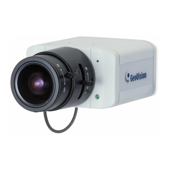
Page 37: Overview
Box Camera 2.3 Overview 2.3.1 GV-BX110D Figure 2-1 Note: The Zoom Screw and Auto Iris Connector are only available in the varifocal model. - Page 38 Connects to power. Status LED See Status LED later in this chapter. Adjusts the zoom of the camera. This Zoom Screw screw is not available for GV-BX110D fixed lens type. Focus Screw Adjusts the focus of the camera. Microphone Records the sounds.
-
Page 39: Gv-Bx120D / 130D Series / 140Dw / 220D Series / 320D Series / 520D-0
1. The Light Sensor (No.11) is only available in GV-BX140DW. Keep the Light Sensor unobscured for accurate light detection. 2. The Iris Screw (No.13) is only available for GV-BX520D-0. 3. The Zoom Screw (No. 15) is not available for GV-BX110D (fixed lens model) and GV-BX130D-1. - Page 40 Name Description Connects to a portable monitor for setting Video Out the focus and angle of Box Camera during initial installation. Inserts a micro SD / SDHC / SDXC card to Memory Card Slot store recording data. Audio Out Connects a speaker for audio output. Audio In Connects a microphone for audio input.
-
Page 41: Connecting The Camera
Box Camera 2.4 Connecting the Camera The Box Camera is designed for indoor use. Please make sure the installing site is shielded from rain and moisture. 2.4.1 GV-BX110D Figure 2-3... - Page 42 If you are using the auto iris model, plug the iris control cable to the Auto Iris Connector on the camera. Use a standard network cable to connect the camera to your network. Optionally connect a speaker and an external microphone. Optionally connect a monitor using an RCA video-out wire.
-
Page 43: Gv-Bx120D / 130D Series / 140Dw / 220D Series / 320D Series / 520D-0
Box Camera 2.4.2 GV-BX120D / 130D Series / 140DW / 220D Series / 320D Series / 520D-0 Figure 2-4 If you are using the auto iris model, plug the iris control cable to the Auto Iris Connector on the camera. Use a standard network cable to connect the camera to your network. -
Page 44: Accessory Installation
Mount the supplied C-mount lens adapter / lens ring to the camera, and then attach the lens onto the camera body. GV-BX110D Install the supplied C-mount lens adapter to extend focal length of GV- BX110D as illustrated below. - Page 45 For GV-BX140DW, a 0.125 mm is provided. Note: The C-mount lens rings are specially designed for Box Camera (except GV-BX110D). Besides the supplied C-mount lens rings, each of these models has already included with the necessary lens ring. Figure 2-6...
-
Page 46: Infrared Illuminators (Optional)
2.5.2 Infrared Illuminators (Optional) If you use an infrared (IR) illuminator with I/O function, follow the steps below to install it. Connect the infrared illuminator to the terminal block on the camera. See 2.6 The I/O Terminal Block. Access the Web interface of the camera. Select Video and Motion, select Video Settings, select Streaming 1 and set the IR Check Function option to be Trigger by Input or Trigger IR by D/N. -
Page 47: I/O Terminal Block
Figure 2-7 Output N/O The GV-BX110D only supports the input device of Wet Contact, 7V ~ 30V. For the output point, please check if your output device meets the following Absolute Maximum Ratings before connecting it to the output point. - Page 48 Box Camera (except GV-BX110D) The GV-BX120D / 130D Series / 140DW / 220D Series / 320D Series / 520D-0 support one digital input and one digital output of dry contact. Function Digital Input Digital Output Figure 2-8 For details on how to enable an installed I/O device, see 14.2 I/O Settings.
-
Page 49: Connecting To Gv-Relay V2 (Optional)
Box Camera 2.6.2 Connecting to GV-Relay V2 (Optional) The Box Camera (except GV-BX110D) can only drive a maximum load of 200mA 5V DC. Connect the camera to a GV-Relay V2 module (optional product) to expand the maximum voltage load. See a comparison on... - Page 50 To connect the Box Camera (except GV-BX110D) to GV-Relay V2, refer to the figure and table below. Figure 2-9 GV-Relay V2 I/O Terminal Block Pin 2 (GND) Pin 3 (Digital Output)
-
Page 51: Chapter 3 Ir Arctic Box Camera
IR Arctic Box Camera Chapter 3 IR Arctic Box Camera The IR Arctic Box Camera series is a variant of the Box Camera series. They are outdoor cameras with IP66 rating. They are designed for day and night surveillance in environments with extreme temperatures. IR Arctic Box Camera Model No. -
Page 52: Packing List
3.1 Packing List • IR Arctic Box Camera • Screw Anchor x 4 • Screw x 4 • Washer x 4 • Big Torx Wrench • Small Torx Wrench • Silica Gel Bag x 2 • Sticker x 2 • GV-PA481 •... -
Page 53: Features
IR Arctic Box Camera 3.2 Features • 1.3 / 2 / 3 / 5 megapixel progressive scan CMOS • Stream 1 from H.264 or MJPEG; Stream 2 from H.264, MPEG4 or MJPEG • Frame rate: Camera Model Frame Rate GV-BX120D-E Up to 30 fps at 1280 x 1024 GV-BX220D-E Up to 30 fps at 1920 x 1080... -
Page 54: Overview
3.3 Overview Figure 3-1 Note: The Iris Screw (No. 7) is only available in GV-BX520D-E. Name Description Desiccant that keeps the camera housing Silica gel bag dry. IR power plug Supplies power to the built-in IR LEDs. Focus Screw Adjusts the focus of the camera. Module screw Holds the module in place. -
Page 55: Installation
IR Arctic Box Camera 3.4 Installation The IR Arctic Box Camera is designed for outdoor use. Mark the installation site and drill four holes for screw anchors. Insert the supplied screw anchors. Secure the camera to the wall using the supplied washers and screws. Figure 3-2 Connect the camera to the network and supply power via the PoE cable. - Page 56 Tilt Adjustment Figure 3-4 Pan Adjustment Figure 3-5 Based on the live view, adjust the focus, zoom and iris (in GV- BX520D-E only) of the camera. Unscrew the cover with the supplied small torx wrench. Figure 3-6...
- Page 57 IR Arctic Box Camera Hold the connectors and unplug them. Figure 3-7 Important: Unscrew and remove the cover carefully. Pulling the cover off may cause damages to the inner wiring of the camera. Adjust the focus, zoom and iris screws. Figure 3-8...
- Page 58 Replace the silica gel bag. Paste the sticker to the front side of the silica gel bag. Press the sticker several times to make sure it adheres properly. Paste the silica gel bag to the indicated place. Figure 3-9 Important: Be sure that the new silica gel bag is concealed in the camera housing within 2 minutes of exposing to open air.
-
Page 59: Connecting The Camera
IR Arctic Box Camera 3.5 Connecting the Camera 3.5.1 Wire Definition Figure 3-10 Wire Color Definition Black (thick) Black BNC TV out Green RCA Audio Out Pink RCA Audio In Optionally connect a speaker (green) and an external microphone (pink). Optionally connect a monitor using a Video Out wire. - Page 60 Connect the camera’s cable to the GV-PA481 PoE adapter as illustrated below. The power and network will be supplied simultaneously. POWER & DATA OUT DATA IN Rear Panel Ethernet Cable Power Hub/Router GV-BX-E Figure 3-11 The status LED of the camera will be on. You are ready to access the live view, adjust the image clarity and configure the basics.
-
Page 61: Notice For Using The Ir Arctic Box Camera
IR Arctic Box Camera 3.6 Notice for Using the IR Arctic Box Camera Ensure that you: • enable IR LED function on the Web interface after loading the default settings. • disable the status LED to reduce reflection when a green light spot appears on the live view. -
Page 62: Disabling Status Led Under Low Light Conditions
3.6.2 Disabling Status LED under Low Light Conditions If you have a green light spot on the live view, this is likely due to insufficient light at the installation site, which causes the status LED to reflect on the camera cover. In this case, it is advisable that you disable the status LED. -
Page 63: Chapter 4 Mini Fixed Dome & Mini Fixed Rugged Dome
Mini Fixed & Rugged Dome Chapter 4 Mini Fixed Dome & Mini Fixed Rugged Dome The Mini Fixed Dome is a fixed, mini-sized ceiling-mount network camera. Two series are available, the Mini Fixed Dome series, which are designed for indoor surveillance and the Mini Fixed Rugged Dome series for outdoor environments. -
Page 64: Packing List
4.1 Packing List • Mini Fixed Dome or Mini Fixed Rugged Dome • Torx Wrench • Self Tapping Screw x 2 • Screw Anchor x 2 • Cable stopper x 1 • Installation sticker (for GV-MDR series only) • Silica gel bag x 2 (for GV-MDR series only) •... -
Page 65: Features
Mini Fixed & Rugged Dome 4.2 Features • 1/3’’ progressive scan CMOS • Megapixel lens • Dual video streams Camera Model Frame Rate Dual video streams from two of H.264, GV-MFD110 MPEG4 or MJPEG GV-MFD series (except GV-MFD110) Stream 1 from H.264 or MJPEG; Stream 2 from H.264, MPEG4 or MJPEG GV-MDR series •... - Page 66 • Day and night function (electronic) • IK7 rating (for GV-MDR series only) • IP66 rating (for GV-MDR series only) • Endurable to low environment temperatures (-20°C ~ 50°C / -4°F ~ 122°F) (for GV-MDR series only) • 2-axis mechanism (GV-MFD series); 3-axis mechanism (GV-MDR series) Camera Type Tilt...
-
Page 67: Overview
Mini Fixed & Rugged Dome 4.3 Overview 4.3.1 GV-MFD110 Figure 4-1 Name Description Resets the camera to factory default. See Default Button 15.3 Restoring to Factory Default Settings. Lens Rotates the les right/left to adjust focus. Focus Screw Loosens the screw to adjust the focus. Tilt Screw Loosens the screw to adjust the tilt angle. -
Page 68: Gv-Mfd120 / 130 / 220 / 320 / 520
4.3.2 GV-MFD120 / 130 / 220 / 320 / 520 Figure 4-2 Name Description Resets the camera to factory default. See Default Button 15.3 Restoring to Factory Default Settings. Lens Receives image inputs. Tilt Screw Loosens the screw to adjust tilt angle. Built-In Microphone Provides one-way audio. -
Page 69: Gv-Mdr120 / 220 / 320 / 520
Mini Fixed & Rugged Dome LED Name Description 1. Link Turns on when the network is connected. 2. ACT Turns on when data are being transmitted. 3. PWR Turns on when power is on. 4. SW RDY (Status) Turns on when the system is ready. 4.3.3 GV-MDR120 / 220 / 320 / 520 Figure 4-3 Name... - Page 70 Name Description Built-In Microphone Provides one-way audio. Resets the camera to factory default. See Default Button 15.3 Restoring to Factory Default Settings. Turns red when the power is on. Flashes Power and status orange light twice when the system is ready.
-
Page 71: Installation
Mini Fixed & Rugged Dome 4.4 Installation To install a Mini Fixed Dome, make sure the installing site is shielded from rain and moisture. 4.4.1 GV-MFD Series Unscrew the housing cover using the supplied torx wrench. Put the camera on the desired location and make 2 marks on the ceiling for screw anchors. -
Page 72: Gv-Mdr Series
For GV-MFD110, adjust image clarity using the GV-IP Device Utility program. For details, see 11.2 Adjusting Image Clarity. Except for GV-MFD110, insert a Micro SD / SDHC / SDXC card into the memory card slot (No. 7, Figure 4-2). 10. Secure the housing cover using the supplied torx wrench. 11. - Page 73 Mini Fixed & Rugged Dome Insert the screw anchors. Unscrew the housing cover using the supplied torx wrench. Secure the camera body to the ceiling with the self-tapping screws. Figure 4-8 Connect the camera to PoE cable. Access the live view. For details, see 11.1 Accessing the Live View. Adjust the angles based on the live view.
- Page 74 Tilt Adjustment Figure 4-10 Rotational Adjustment Figure 4-11 Insert a Micro SD / SDHC / SDXC card into the memory card slot (No. 9, Figure 4-3). 10. Secure the housing cover using the supplied torx wrench. 11. Optionally conceal the cable opening with the supplied cable stopper. Cable stopper Figure 4-12...
-
Page 75: Connecting The Camera
Mini Fixed & Rugged Dome 4.5 Connecting the Camera Refer to the wire definition and illustrations below to connect the power and network. 4.5.1 Wire Definition GV-MFD120 / 130 / 220 / 320 / 520 The data cable provides connections for power and network access. The wires are illustrated and defined below: Figure 4-13 Wire Color... -
Page 76: Power And Network Connection
4.5.2 Power and Network Connection For GV-MFD120 / 130 / 220 / 320 / 520 , there are two ways to supply power to the camera: • Use a Power over Ethernet (PoE) adapter to connect the camera to the network, and the power will be provided at the same time. •... -
Page 77: Vehicle Installation
Mini Fixed & Rugged Dome 4.5.3 Vehicle Installation To install the Mini Fixed Rugged Dome on a vehicle, clip the ferrite core to the camera cable. In accordance to EN 50155, the ferrite core is used for reduction of the cable-based and radiated interferences, ensuring stable image quality. -
Page 78: Chapter 5 Bullet Camera
Chapter 5 Bullet Camera The Bullet Cameras is specifically designed for outdoors and is weather- sealed and IP66 rating. The camera also features IR LEDs for infrared illumination in night vision applications. Four models are available: Model No. Specifications Description GV-BL110D 1.3 MP, H.264 1.3 MP, H.264,... -
Page 79: Packing List
Bullet Camera 5.1 Packing List • Bullet Camera • Lens (Megapixel and Built-In 16 IR LEDs) • Self Tapping Screw x 3 • Plastic Screw Anchor x 3 • Torx Wrench x 2 • Sun-Shield Cover Kit (1 Sun-Shield Cover, 2 Philips Head Screws, 2 Plastic Screw Spacers and 2 Hexagon Screws included) •... -
Page 80: Features
5.2 Features • 1/3’’ progressive scan CMOS for GV-BL110D / 120D 1/2.5’’ progressive scan CMOS for GV-BL130D / 220D / 320D • Dual video streams GV-BL110D: Dual streams from H.264, MPEG4 or MJPEG GV-BL120D / 220D / 320D: Stream 1 from H.264 or MJPEG; Stream 2 from H.264, MPEG4 or MJPEG •... -
Page 81: Overview
Bullet Camera 5.3 Overview Figure 5-1 Name Description Receives a Micro SD / SDHC / SDXC Memory Card Slot memory card. Zoom Screw Holds the zoom lens in place. Focus Screw Holds the focus lens in place Resets all configurations to factory default. Default Button See 15.3. -
Page 82: Installation
5.4 Installation These instructions describe the basic installation of the Bullet Camera. Slide the cable clamp to the camera base. Figure 5-2 Install the Bullet Camera to the wall. Figure 5-3 Remove the protection sticker from the camera’s cover Connect the power, network and other wires to the Bullet Camera. See 5.4.1 Connecting the Camera. -
Page 83: Connecting The Camera
Bullet Camera Access the live view. For details, see 11.1. Accessing the Live View. Adjust angles of the camera body based on the live view. Three shafts can be adjusted. See 5.4.2 Adjusting the Angles. Loosen the camera’s cover, adjust the focus of the camera and optionally insert a micro SD / SDHC / SDXC card into the SD card slot. - Page 84 Wire Color Definition Digital In Brown DC 12V+ / AC 24V- Orange Digital Out Black DC 12V- / AC 24V+ Yellow Ground Red RCA Audio in Green RCA Audio out Power Connection There are two ways to supply power to the camera: •...
- Page 85 Bullet Camera Voltage Load Expansion (Optional) The camera can only drive a maximum load of 200mA 5V DC. Connect the camera to a GV-Relay V2 module (optional product) to expand the maximum voltage load. See a comparison on maximum voltage loads with and without GV-Relay below: Maximum Voltage Load Models...
- Page 86 To connect the GV-Relay V2 module to the Bullet Camera, refer to the figure and table below. Output Devices Connect to Power Figure 5-7 GV-Relay V2 Bullet Camera Ground (Yellow) Digital Out (Orange)
-
Page 87: Adjusting The Angles
Bullet Camera 5.4.2 Adjusting the Angles The Bullet Camera is designed to be adjustable in three shafts for easy and flexible installation. First Shaft You can adjust the camera body by 360 degrees to the right or the left. Unscrew the panning lock screw with the torx wrench. Panning Lock Screw Torx Wrench Figure 5-8... - Page 88 Second Shaft You can adjust the camera body up and down by 90, 112.5, 135, 157.5 or 180 degrees by using the gears inside the camera body and the camera base. Unscrew the tilting lock screw with the torx wrench. Tilting Lock Screw Torx Wrench Figure 5-10...
-
Page 89: Bullet Camera
Bullet Camera Adjust the angle of camera body to 90, 112.5, 135, 157.5 or 180 degrees. Then move the camera base to the left to combine the gears. Figure 5-12 Fasten the tilting lock screw. Third Shaft You can adjust the camera base by 360 degrees. Unscrew the base fixing screw with the torx wrench. - Page 90 Adjust the angle of camera base, and fasten the base fixing screw. Figure 5-14...
-
Page 91: Adjusting Lens And Inserting A Memory Card
Bullet Camera 5.4.3 Adjusting Lens and Inserting a Memory Card To adjust the camera’s lens to produce a clear image and insert a micro SD / SDHC / SDXC card into the SD card slot, follow the steps below. Loosen the camera’s cover. Figure 5-15 Remove the silica gel bag. - Page 92 If you want to insert a micro SD / SDHC / SDXC card, follow the steps below. Loosen the fixing screw. Figure 5-17 Slightly pull out the camera module. Insert a micro SD / SDHC / SDXC card into the memory card slot.
-
Page 93: Installing The Sun-Shield Cover
Bullet Camera 5.4.4 Installing the Sun-Shield Cover After setting up the Bullet Camera, now you can install the sun-shield cover to the camera. Fasten the hexagon screws either on top or below the camera. Figure 5-19 Put the sun-shield cover on top of hexagon screws. Make sure to aim the rear hexagon screw at the edge of the sun-shield cover’s aperture for optimal sun-shield performance. -
Page 94: Chapter 6 Ptz Camera
Chapter 6 PTZ Camera The GV-PTZ010D camera is a ceiling-mount device that provides panning, tilting and zooming functions. The camera is designed to monitor a wide area and also to focus on a specific part on the live view when suspicious events occur. -
Page 95: Packing List
PTZ Camera 6.1 Packing List • GV-PTZ010D • Mounting Base • Mounting Cover • Wall Mount Bracket • Screw Anchor x 3 • Long Screw x 3 • Short Screw x 3 • Round Screw x 3 • DC 12V Power Adapter •... -
Page 96: Features
6.2 Features • 1/4" CCD image sensor • Dual streams from H.264, MPEG4 or MJPEG • Up to 30 fps at 704 x 480 / Up to 25 fps at 704 x 576 • Day and night function (electronic) • 10x optical zoom lens •... -
Page 97: Overview
PTZ Camera 6.3 Overview Figure 6-1 Name Description DC 12V / AC 24V Connects to a DV 12V or AC 24V Power Terminal Block Adapter. LAN/PoE Connects to a 10/100 Ethernet or PoE. I/O Terminal Block For details, see 6.7 I/O Terminal Block. Inserts a micro SD / SDHC / SDXC card to Memory Card Slot store recording data. - Page 98 Name Description Turns green when the power is on and Power LED turns off when the power is off. Microphone Records the sounds. Resets to system default settings. For Default details, see 15.3 Restoring to Factory Default Settings.
-
Page 99: Installation
PTZ Camera 6.4 Installation The GV-PTZ010D / GV-PT110D camera is designed for indoor usage. Please make sure that the installing location is shielded from rain and moisture. There are two ways to mount the PTZ / PT Camera: Ceiling Mount and L-Shaped Wall Mount. 6.4.1 Ceiling Mount Use the mounting base to make 3 marks on the wall for screw anchors. - Page 100 Fix the mounting base (now with the PTZ / PT Camera attached) to the wall with 3 long screws. Figure 6-4 Put on the mounting cover. To fit the installation environment, you can cut the parts indicated by arrows to make an opening for wires and cables.
-
Page 101: L-Shaped Wall Mount
PTZ Camera 6.4.2 L-Shaped Wall Mount You may wall-mount the GV-PTZ010D / GV-PT110D camera with or without the mounting cover. Take the wall mount bracket and make 2 marks on the wall for screw anchors. Figure 6-6 Drill the marks and insert 2 screw anchors. Insert the long screws and leave enough distance (approximately 2 mm) to hang the wall mount bracket later. - Page 102 Hang the wall mount bracket on the screws and push the wall mount bracket downward. Make sure the long screws are tightened. Figure 6-8 Without Mounting Cover Attach the wall mount bracket with the PTZ / PT Camera using 3 washers and 3 round screws.
- Page 103 PTZ Camera With Mounting Cover To install the mounting cover, attach the mounting base to the camera and then put on the mounting cover. See steps 3 and 5 in the Ceiling Mount section. Attach the wall mount bracket with the PTZ / PT Camera using 3 round screws.
-
Page 104: Connecting The Camera
6.5 Connecting the Camera Figure 6-11 Use a standard network cable to connect the camera to your network. Optionally connect a speaker and an external microphone. Connect power using one of the following methods: • plugging the supplied power adapter to the power port. •... -
Page 105: Focus Adjustment
PTZ Camera 6.6 Focus Adjustment On initial installation, it is advised that you adjust the focus for image clarity. Print out the diagram of radiating lines included on Software CD and hang up the diagram at the surveillance area. Use the Zoom In / Out and Focus In / Out buttons on the PTZ control panel from the Web interface (No.4 and 5, Figure 6-15) and adjust the PTZ Camera until it displays clear radiating lines as shown in picture on the left. -
Page 106: I/O Terminal Block
6.7 I/O Terminal Block The 3-pin terminal block, located on the back panel of the PTZ Camera, provides the interface to one digital input and one digital output. The I/O terminal block can be used for applications such as motion detection, event alerts via E-Mail and FTP, and center monitoring through Center V2 and VSM. -
Page 107: Voltage Load Expansion (Optional)
PTZ Camera 6.7.2 Voltage Load Expansion (Optional) The camera can only drive a maximum load of 200mA 5V DC. Connect the camera to a GV-Relay V2 module (optional product) to expand the maximum voltage load. See a comparison on maximum voltage loads with and without GV-Relay below: Maximum Voltage Load Model... -
Page 108: Ptz Control
6.8 PTZ Control After you have installed the PTZ Camera on network and accessed the camera’s Web interface you are ready to configure the PTZ Camera. To see how to install the PTZ Camera on network, see Getting Started, Chapter 11. To see how to access to live image, see 12.1 Accessing Your Surveillance Images. - Page 109 PTZ Camera Buttons on the PTZ control panel: Name Description Exit Closes the PTZ control panel. Moves the PTZ Camera to 8 directions: Pan / Tilt Control up, down, left, right, left up, left down, right up and right down. Brings the camera view back to the home Home point where the camera faces front at a 90...
-
Page 110: Automatic Focus
6.8.2 Automatic Focus When the camera view is fuzzy, you may use the auto focus feature to obtain a sharper view. On the PTZ control panel, click the Option button (No. 6, Figure 6-15) and select AF for automatic focus. 6.8.3 PTZ Camera Settings Accessing the PTZ Camera Settings To access PTZ camera settings, click the Option button (No. - Page 111 PTZ Camera PT Speed: Determines the panning (horizontal movement) and tilting (vertical movement) speed when using the Pan / Tilt Control buttons on the PTZ control panel. The drop-down list contains 5 speed settings: 1 is the slowest and 5 the fastest. Zoom Speed: Determines the zooming speed.
-
Page 112: Image Settings
6.8.4 Image Settings Image Setting provides features on iris control, white balance, image orientation and other image processing tools to generate clearer images. To access these features, open the VISCA OSD Configuration dialog box and select Image Setting. [Iris] adjusts the amount of exposure. ALC: Automatic Light Control (ALC) is used to adjust light levels. - Page 113 PTZ Camera AWB: Automatic White Balance (AWB) automatically compensates for colors under different light levels. AWB is ideal for scenes with a fixed light source. Use the slider to select from 0 to 8. A higher value produces a brighter image and a lower value produces a dimmer image.
- Page 114 Freeze: Instantly freezes the live view image when On is selected. AGC: Automatic Gain Control (AGC) utilizes an electronic circuit which amplifies video signal when the signal strength falls below a given value due to lack of the light on the camera. Adjust camera sensitivity to provide clear images.
-
Page 115: Preset Settings
PTZ Camera 6.8.5 Preset Settings For PTZ Camera to automatically move toward a point in live view, establish a Preset. A Preset is a point in live view that can be configured and saved for future use. The PTZ Camera allows up to 256 Preset points. For details on the maximum number of Preset points, see 6.8.3 PTZ Camera Settings. - Page 116 Renaming a Preset Point To rename a Preset point: Click the Option button (No. 6, Figure 6-15), select Preset Set and select Naming. The dialog box appears. Figure 6-18 Click the Preset point you wish to rename and type the new name in the blank at the top.
- Page 117 PTZ Camera Starting and Stopping a Preset Point To start a Preset movement, click the Option button (No. 6, Figure 6-15), select Preset Go, and select a Preset number which has been set previously. Alternatively, you may use the number pad on the PTZ control panel to enable a Preset movement: Click the Show Preset button (No.
-
Page 118: Sequence Settings
6.8.6 Sequence Settings For PTZ Camera to automatically perform a series of movements, you can configure a Sequence. A Sequence links up more than two Preset points to form a sequence of movements. Up to 8 Sequences can be created. Configuring a Sequence After you have configured the Preset points you wish the camera to follow (for details, see 6.8.5 Preset Settings), you are ready to... - Page 119 PTZ Camera Use the Preset drop-down list to select the Preset points for the Sequence. Use the Dwell Time drop-down list to select the staying time that the camera stays at the Preset point. The dwell time ranges from 0 to 127 seconds at an interval of 0.5 second.
-
Page 120: Auto Pan Settings
6.8.7 Auto Pan Settings For the PTZ Camera to survey a horizontal view, establish an Auto Pan. Up to 4 sets of Auto Pan can be created. Configuring an Auto Pan To configure a horizontal movement: Adjust the angle of the camera view using the Up and Down Control buttons since any vertical movements of the camera will not be recorded by Auto Pan. - Page 121 PTZ Camera Configuring the Speed of Auto Pan You can configure the speed for each set of Auto Pan differently: Open the VISCA OSD Configuration dialog box and select Advance. Figure 6-20 Select the Auto Pan number you wish to configure and select the Speed.
-
Page 122: Rebooting The Camera
Starting and Stopping Autopan To start an Auto Pan, click the Option button (No. 6, Figure 6-15), select Auto and select a desired Auto Pan number. The PTZ Camera will first return to the starting position of the selected Auto Pan and proceeds with the selected Auto Pan movement. -
Page 123: System Configuration
PTZ Camera 6.8.8 System Configuration To configure lens settings, open the VISCA OSD Configuration dialog box and select System Configure. Figure 6-21 Zoom + AF: Automatically focuses after zooming. It is advised to use this feature with a zooming distance of at least 1 meter. Digital Zoom: Allows up to 10x Digital Zoom. -
Page 124: Chapter 7 Pt Camera
Chapter 7 PT Camera The GV-PT110D camera is a ceiling-mount device that features panning and tilting functions. The GV-PT110D is designed to monitor a wide area and to focus on a selected point on live view when suspicious events occur. 7.1 Packing List •... - Page 125 PT Camera • DC 12V Power Adapter • Washer x 3 • GV-PT110D Software CD • GV-PTZ110D / GV-PTZ010D Quick Start Guide • GV-NVR Software DVD • GV-NVR Quick Start Guide...
-
Page 126: Features
7.2 Features • 1.3 megapixel progressive scan CMOS • Dual streams from H.264, MPEG4 or MJPEG • Up to 15 fps at 1280 x 1024 • Day and night function (with removable IR-cut filter) • Pan and tilt (Pan: -175° ~ 175°; Tilt: -45° ~ 90°) •... -
Page 127: Overview
PT Camera 7.3 Overview Figure 7-1 Name Description DC 12V / AC 24V Connects to a DV 12V or AC 24V Power Terminal Block Adapter. LAN / PoE Connects to a 10/100 Ethernet or PoE. I/O Terminal Block For details, see 7.7 I/O Terminal Block. Inserts a micro SD / SDHC / SDXC card to Memory Card Slot store recording data. - Page 128 Name Description Turns green when the system operates Status LED normally and turns off when system error occurs. Turns green when the power is on and Power LED turns off when the power is off. Manually rotates this ring left or right to Focus Ring adjust focus.
-
Page 129: Installation
PT Camera 7.4 Installation For installation procedures of the GV-PT110D, see 6.4 Installation. 7.5 Connecting the Camera For procedures of connecting the GV-PT110D, see 6.5 Connecting the Camera. 7.6 Focus Adjustment After you have followed 5.5 Connecting the Camera and connected all the necessary cables and wires, follow the steps below to adjust image clarity. -
Page 130: I/O Terminal Block
7.7 I/O Terminal Block The 3-pin terminal block, located on the back panel of the PT Camera, provides the interface to one digital input and one digital output. The I/O terminal block can be used for applications such as motion detection, event alerts via E-Mail and FTP, and center monitoring through Center V2 and VSM. -
Page 131: Pt Control
PT Camera 7.8 PT Control The GV-PT110D shares similar user interfaces and features with the GV- PTZ010D camera. The supported functions are listed in the table below. Supported Function Description PT Control Panel The following buttons on the PT control panel are available: Exit, Pan / Tilt Control, Home, Option and Show Preset. - Page 132 Supported Function Description Sequence A Sequence consists of a series of Preset points. Configure a Sequence to direct the camera to perform s series of movements. For details, see 6.8.6 Sequence Settings. Auto Pan The camera can be configured to monitor the surveillance area in a horizontal movement.
-
Page 133: Chapter 8 Vandal Proof Ip Dome
Vandal Proof IP Dome Chapter 8 Vandal Proof IP Dome The Vandal Proof IP Domes are designed for outdoor usage. They are equipped with automatic infrared cut filters for day and night surveillance. Model options range from 1.3. to 3 megapixels: Model No. -
Page 134: Packing List
8.1 Packing List • Vandal Proof IP Dome • Silica Gel Bag x 2 • Screw Anchor x 4 • Torx Wrench x 1 • Ceiling Screw x 4 • Blue Screw x 3 • T-Cap Screw x 3 • Small Screw Cap x 3 •... -
Page 135: Features
Vandal Proof IP Dome 8.2 Features • 1/3’’ progressive scan CMOS for GV-VD120D 1/2.5’’ progressive scan CMOS for GV-VD220D / 320D • Dual video streams. Stream 1 from H.264 or MJPEG; stream 2 from H.264, MPEG4 or MJPEG • Up to 30 fps at 1280 x 1024 for GV-VD120D Up to 30 fps at 1920 x 1080 for GV-VD220D Up to 20 fps at 2048 x 1536 for GV-VD320D •... -
Page 136: Overview
8.3 Overview Figure 8-1 Name Description Turns on (green) when the power is on Power LED and turns off when there is no power supply. Turns on (green) when the system Status LED operates normally and turns off when system error occurs. Resets to factory default. -
Page 137: Installation
Vandal Proof IP Dome 8.4 Installation The Vandal Proof IP Dome is designed for outdoors. With the standard packing, there are two ways to install the Vandal Proof IP Dome: hard- ceiling mount and in-ceiling mount. 8.4.1 Hard-Ceiling Mount Figure 8-2 Unpack the camera package and take out the camera body. - Page 138 Unscrew thread lock Unscrew the inner housing Take out the camera body...
- Page 139 Vandal Proof IP Dome Mark the position of four screw holes on the desired installation location, and drill holes in the marked locations. Drill the ellipse part if you wish to put the wires through it. Figure 8-3 Insert the screw anchors to the 4 holes on the ceiling. Secure the back cover to the ceiling with 4 ceiling screws.
- Page 140 Connect the network, power and other cables to the camera. See 8.5 Connecting the Camera. Access the live view. See 11.1 Accessing the Live View. Based on the live view, adjust the camera to a desired angle as illustrated below. Tip: The 3-axis mechanism offers flexible and easy installation.
- Page 141 Vandal Proof IP Dome Rotational Adjustment Figure 8-7 10. Adjust image clarity using the GV-IP Device Utility program. For details, see 11.2 Adjusting Image Clarity. 11. Screw on the thread lock as shown in step 1. 12. Replace the silica gel bag on the camera body within 2 minutes of opening the silica gel bag package.
-
Page 142: In-Ceiling Mount
8.4.2 In-Ceiling Mount Figure 8-8 Follow step 1 in 8.4.1 Hard-Ceiling Mount section to remove the housing cover, thread lock and back cover, and take out the camera body. Cut out a circle with a diameter of 142 mm on the ceiling. Insert a blue screw to the indicated holes on the camera body. - Page 143 Vandal Proof IP Dome Screw in a plastic clip to the blue screw, hold it with one hand and use a screw driver to rotate the blue screw until the plastic clip moves half way down. Figure 8-10 Secure a T-cap on top of the blue screw with a small screw cap and a T-cap screw.
- Page 144 Insert the camera to the ceiling with the plastic screws moved inward. Figure 8-12 Move the blue screws out and rotate the blue screw with a screw driver until the plastic clip and the bottom of the camera body clamps the ceiling tightly.
-
Page 145: Connecting The Camera
Vandal Proof IP Dome 8.5 Connecting the Camera Connect your Vandal Proof IP Dome to power, network and other cables needed. 8.5.1 Wire Definition The cables of Vandal Proof IP Dome are illustrated and defined below. Figure 8-14 Wire Color Definition Black (thick) Shielding Ground... -
Page 146: Power Connection
8.5.2 Power Connection There are two ways to supply power to the camera: • Use a Power over Ethernet (PoE) adapter to connect the camera to the network, and the power will be provided at the same time. • Use the supplied Terminal Block and power adapter. Follow the steps below to connect the Terminal Block and the power adapter. -
Page 147: Voltage Load Expansion (Optional)
Vandal Proof IP Dome 8.5.3 Voltage Load Expansion (Optional) The camera can only drive a maximum load of 200mA 5V DC. Connect the camera to a GV-Relay V2 module (optional product) to expand the maximum voltage load. See a comparison on maximum voltage loads with and without GV-Relay: Maximum Voltage Load Models... -
Page 148: Chapter 9 Fixed Ip Dome
Chapter 9 Fixed IP Dome The Fixed IP Dome is an indoor device designed with 3-axis mechanism for easy and flexible installation. The Fixed IP Dome also features IR LED for infrared illumination during low light conditions. Three models are available: Model No. -
Page 149: Packing List
Fixed IP Dome 9.1 Packing List 9.1.1 Packing List for Hard-Ceiling Mount • Fixed IP Dome • Torx Wrench x 1 • Mounting Plate x 1 • Short Screw Anchor x 3 • Ceiling Screw x 3 • Plate Screw x 3 •... -
Page 150: Packing List For In-Ceiling Mount
9.1.2 Packing List for In-Ceiling Mount • In-Ceiling Housing Cover • Mounting Plate x 1 • Mounting Bracket x 3 • Copper Pillar x 3 • Copper Pillar Screw x 6 • Bracket Screw x 3 • Thread Lock Screw x 1 •... -
Page 151: Features
Fixed IP Dome 9.2 Features • 1/3’’ progressive scan CMOS for GV-FD120D 1/2.5” progressive scan CMOS for GV-FD220D / 320D • Dual video streams. Stream 1 from H.264 or MJPEG; stream 2 from H.264, MPEG4 or MJPEG • Up to 30 fps at 1280 x 1024 for GV-FD120D Up to 30 fps at 1920 x 1080 for GV-FD220D Up to 20 fps at 2048 x 1536 for GV-FD320D •... -
Page 152: Overview
9.3 Overview Figure 9-1 Name Description Focus Screw Adjusts the focus of the camera. Zoom Screw Adjusts the zoom of the camera. Rotational Screw Loosens to adjust the camera angle. Tilt Screw Loosens the screw to tilt the camera. Pan Disc Loosens to pan the camera. - Page 153 Fixed IP Dome Name Description Connects I/O devices. For details, see 9.6 I/O Terminal Block I/O Terminal Block. DC 12V Port Connects to power. Turns on (green) when the system Status LED operates normally and turns off when system error occurs. Turns on (green) when the power is on Power LED and turns off when there is no power...
-
Page 154: Installation
9.4 Installation The Fixed IP Dome is designed for indoors. With the standard packing, there are three ways to install the Fixed IP Dome: hard-ceiling mount, in- ceiling mount and wall-surface mount. 9.4.1 Hard-Ceiling Mount Figure 9-2 Paste the supplied sticker onto a desired location on the ceiling. Drill the three red dots and the ellipse mark only if you wish to run the wires into the ceiling. - Page 155 Fixed IP Dome Take out the camera body Figure 9-4 Secure the camera body to the mounting plate with three ceiling screws. Figure 9-5 Connect the network, power and other cables to the camera. See 9.5 Connecting the Camera. Access the live view. See 11.1 Accessing the Live View.
- Page 156 Based on the live view, adjust the camera to a desired angle as illustrated below. Tip: The 3-axis mechanism offers flexible and easy ceiling / wall installation. Pan Adjustment Figure 9-6 Tilt Adjustment Figure 9-7...
- Page 157 Fixed IP Dome Rotational Adjustment Figure 9-8 Adjust image clarity using the GV-IP Device Utility program. For details, see 11.2 Adjusting Image Clarity. Secure the housing cover as shown in step 2. Remove the indicated part when necessary. Figure 9-9 Note: Adjust the black mask inside the housing cover to make sure the camera view is not obscured.
-
Page 158: In-Ceiling Mount
9.4.2 In-Ceiling Mount Figure 9-10 Follow step 2 in the 9.4.1 Hard-Ceiling Mount to remove the housing cover and take out the camera body. Paste the supplied sticker onto a desired location on the ceiling and cut a circle on the ceiling along the edge of the sticker. On the mounting plate, locate the 3 holes labeled as 1 and insert the 3 copper pillars from the back side. - Page 159 Fixed IP Dome From the side with the numbering, secure the copper pillars with 3 copper pillar screws. Figure 9-12 Place the 3 mounting brackets at the indent next to the copper pillars (labeled as 2 on the mounting plate) and secure them using the 3 bracket screws.
- Page 160 Place the mounting plate on the camera body with the copper pillars inserted in the locations indicated below. The arrow on the mounting plate should be pointing toward the front of the camera. Figure 9-14 From the bottom of the camera, secure the copper pillars using the 3 copper pillars screws.
- Page 161 14. Use the housing cover thread and the thread lock screw to attach the housing cover to the camera body. Figure 9-16 15. Place the housing cover on the camera body with the GeoVision logo pointing toward the front of the camera. Figure 9-17...
-
Page 162: Wall-Surface Mount
9.4.3 Wall-Surface Mount Figure 9-18 Follow step 2 in 9.4.1 Hard-Ceiling Mount section to remove the housing cover and take out the camera body. Paste the supplied sticker onto a desired location on the wall. Drill the three red dots, and the ellipse mark only if you wish to run the wires into the wall. - Page 163 Fixed IP Dome Access the live view. See 11.1 Accessing the Live View. Follow steps 6 and 7 in 9.4.1 Hard-Ceiling Mount section to adjust the angle, focus and zoom of the camera. Follow step 8 in 9.4.1 Hard-Ceiling Mount section to secure the housing cover.
-
Page 164: Connecting The Camera
9.5 Connecting the Camera Figure 9-20 Use a standard network cable to connect the camera to your network. Optionally connect a speaker and an external microphone. Optionally connect a monitor using a Video Out wire. Enable this function by selecting your signal format at the TV Out field on the Web interface. -
Page 165: I/O Terminal Block
Fixed IP Dome 9.6 I/O Terminal Block The terminal block, located on the back panel of the Fixed IP Dome, provides the interface to one input and one output devices. The I/O terminal block can be used for applications such as motion detection, event alerts via E-Mail and FTP, and center monitoring through Center V2 and VSM. -
Page 166: Voltage Load Expansion (Optional)
9.6.2 Voltage Load Expansion (Optional) The camera can only drive a maximum load of 200mA 5V DC. Connect the camera to a GV-Relay V2 module (optional product) to expand the maximum voltage load. See a comparison on maximum voltage loads with and without GV-Relay below: Maximum Voltage Load Models... -
Page 167: Chapter 10 Cube Camera
Cube Camera Chapter 10 Cube Camera The Cube Camera is a light weighted wired / wireless network camera designed for indoor usage. Its simple design allows for fast and easy installation and fixed-spot surveillance once installed. Four models are available: Model No. -
Page 168: Packing List
10.1 Packing List • Cube Camera • Supporting Rack • Screw x 3 • Screw Anchor x 3 • DC 5V or DC 12V Power • DC 5V Power Adapter Adapter (for GV-CBW120 / 220) (for GV-CB120 / 220) • GV-IPCAM H.264 Quick •... -
Page 169: Features
Cube Camera 10.2 Features • 1/2.5’’ progressive scan CMOS • Stream 1 from H.264 or MJPEG; stream 2 from H.264, MPEG4 or MJPEG • Up to 30 fps at 1280 x 1024 for GV-CB120 / CBW120 Up to 30 fps at 1920 x 1080 for GV-CB220 / CBW220 •... -
Page 170: Overview
10.3 Overview Figure 10-1 Name Description Microphone Receives sounds. Speaker Plays sounds. Connects to a 10/100 Ethernet. Turns red when the system powers on. Status LED Turns orange when the system is ready. Turns green when the camera is connected to the Internet through wires. -
Page 171: Installation
Cube Camera 10.4 Installation Follow the steps below to install, connect to and adjust your Cube Camera and Wireless Cube Camera. Put the supporting rack on the desired location and make marks for screw anchors. Figure 10-2 Drill the marks and insert the screw anchors. Secure the supporting rack onto the wall using the supplied screws. - Page 172 Connect the network and power cables to the camera. See 10.5 Connecting the Camera. Access the live view. See 11.1 Accessing the Live View. Adjust the angle of the camera based on live view and fasten the indicated screw. Figure 10-4 For GV-CBW120/220, to connect to the Internet through wireless service, follow the steps in 11.1.3 Configuring the Wireless Connection.
-
Page 173: Connecting The Camera
Cube Camera 10.5 Connecting the Camera Figure 10-5 Use a standard network cable to connect the camera to your network. Power on using the supplied power adapter. The status LED of the camera will be orange. -
Page 174: Chapter 11 Advanced Cube Camera
Chapter 11 Advanced Cube Camera The Advanced Cube Camera integrates the passive infrared (PIR) sensor and the alarm LED. It can detect the movement and illuminate the LED within 5 meters. It also offers wireless connection to the network for flexible installation. -
Page 175: Packing List
Advanced Cube Camera 11.1 Packing List • Advanced Cube Camera • Supporting Rack • Screw x 3 • Screw Anchor x 3 • DC 5V Power Adapter • GV-IPCam H.264 Software • GV-IPCAM H.264 Quick • GV-NVR Software DVD Start Guide •... -
Page 176: Features
11.2 Features • 1/2.5’’ progressive scan CMOS • Stream 1 from H.264 or MJPEG; stream 2 from H.264, MPEG4 or MJPEG • Up to 30 fps at 1280 x 1024 for GV-CA120 / CAW120 Up to 30 fps at 1920 x 1080 for GV-CA220 / CAW220 •... -
Page 177: Overview
Advanced Cube Camera 11.3 Overview 2 3 4 5 6 7 Figure 11-1 Name Description Speaker Plays sounds. PIR sensor Passive infrared sensor. Microphone Receives sounds. When the PIR sensor detects the Alarm LED movement, the LED lights up. Reflects monitoring status of the camera. Monitoring LED See the below table. - Page 178 Status Description Turns on orange light when you see Live View the live view. Turns on red light when you start Monitoring monitoring. - Turns on green light when the Ready system is ready. - Flashes green light when you load default value.
-
Page 179: Installation
Advanced Cube Camera 11.4 Installation Follow the steps below to install, connect to and adjust your Advanced Cube Camera and Wireless Advanced Cube Camera. Put the supporting rack on the desired location and make marks for screw anchors. Figure 11-2 Drill the marks and insert the screw anchors. - Page 180 Connect the network and power cables to the camera. See 12.5 Connecting the Camera. Access the live view. See 13.1 Accessing the Live View. Adjust the angle of the camera based on live view and fasten the indicated screw. Figure 11-4 For GV-CAW120/220, to connect to the Internet through wireless service, follow the steps in 13.1.3 Configuring the Wireless Connection.
-
Page 181: Connecting The Camera
Advanced Cube Camera 11.5 Connecting the Camera Figure 11-5 Use a standard network cable to connect the camera to your network. Connect power using one of the following methods: • plugging the supplied power adapter to the power port. • using the Power over Ethernet (PoE) function and the power will be provided over the network cable. -
Page 182: Chapter 12 Getting Started
• GV-IPCAM H.264 with DHCP firmware V1.07 or later An unused IP address is automatically (except GV-BX110D, assigned by the DHCP server to the BL110D, GV-MFD110, camera when the camera is connected to GV-PT110D, GV- the network. Refer to 12.1.1 Checking... - Page 183 • GV-BL110D • GV-MFD110 • To avoid IP conflict with other GeoVision GV-PT110D IP devices, it is advisable to re-assign a • GV-PTZ010D different IP address. See 12.1.2 Configuring the IP Address for more...
-
Page 184: Checking The Dynamic Ip Address
12.1.1 Checking the Dynamic IP Address Follow the steps below to look up the IP address and access the Web interface. Install the GV-IP Device Utility program included on the GV-IPCAM H.264 Software CD. Note: The PC installed with GV-IP Device Utility must be under the same LAN with the GV-IPCAM H.264 you wish to configure. -
Page 185: Getting Started
Getting Started Find the camera with its Mac Address, click on its IP address and select Web Page. Figure 12-2 The login page appears. Figure 12-3 Type the default ID and password admin and click Apply to log in. -
Page 186: Configuring The Ip Address
12.1.2 Configuring the IP Address Follow the steps below to configure the IP address. Open your web browser, and type the default IP address http://192.168.0.10. In both Login and Password fields, type the default value admin. Click Apply. In the left menu, select Network and then LAN to begin the network settings. - Page 187 Getting Started Important: If Dynamic IP Address or PPPoE is enabled, you need to know which IP address the camera will get from DHCP server or ISP to log in. If your camera is installed in the LAN, use the GV-IP Device Utility to look up its current dynamic IP address.
-
Page 188: Configuring The Wireless Connection
12.1.3 Configuring the Wireless Connection For GV-CBW120/220 and GV-CAW120/220, you may choose to create wireless connection to the Internet. To set up the wireless LAN for the first time, power on and connect a standard network cable to the camera. An IP address will be automatically assigned to the camera. - Page 189 Getting Started C. Select Ad-Hoc or Infrastructure for the Network type. D. Select the Authentication Type using the drop-down list. You can also obtain this information by clicking the Access Point Survey button. E. Type the WPA-PSK Pre-shared Key or WEP depending on the encryption setting for the Access Point.
- Page 190 Enable wireless LAN. A. On the Web interface, select Network and LAN. This page appears. Figure 12-6 B. Select Wireless for Optional Network Type C. To use a dynamic IP address assigned by the DHCP server, select Dynamic IP address. To use a fixed IP address, select Static IP address and type the IP address information.
-
Page 191: Adjusting Image Clarity
Getting Started 12.2 Adjusting Image Clarity Note the procedures described in this section only apply to Box Camera, IR Arctic Box Camera, GV-MFD110, Bullet Camera, PT Camera, Vandal Proof IP Dome and Fixed IP Dome. To adjust focus of a PTZ camera, refer to 6.6 Focus Adjustment;... - Page 192 On the GV-IP Utility window, click the button to search for the IP devices connected in the same LAN. Click the IP Address of the camera you desire. A drop-down list appears. Figure 12-7 Select Focus Value. The Login dialog box appears. Figure 12-8...
- Page 193 Getting Started Type the user name and password of the camera selected. The default is admin for both user name and password. This window appears. Figure 12-9 For GV-VD120D / 121D, VD-220D / 221D and VD-320D / 321D, hold the supplied Focus Adjustment Cap over the camera view. For details, see 12.2.1 Using Focus Adjustment Cap for details.
-
Page 194: Using Focus Adjustment Cap
12.2.1 Using Focus Adjustment Cap There are two types of Focus Adjustment Caps for GV-VD120D / 121D, VD-220D / 221D and VD-320D / 321D. Hold and close the Focus Adjustment Cap to the lens in order to simulate the IK10+ housing cover before installing it. - Page 195 Getting Started Do not leave a distance between the Focus Adjustment Cap and the camera.
-
Page 196: Locations Of Adjustment Screws
12.2.2 Locations of Adjustment Screws Models Adjustment Screws GV-BX110D Box Camera GV-MFD110 Bullet Camera... - Page 197 Getting Started Models Adjustment Screws PT Camera Vandal Proof IP Dome Fixed IP Dome Note: GV-BX110D (fixed lens) and GV-BX130D-1 do not contain a Zoom Screw.
-
Page 198: Configuring The Basics
12.3 Configuring the Basics Once the camera is properly installed, the following important features can be configured using the browser-based configuration page and are discussed in the following sections in this manual: • Date and time adjustment: see 14.8.1 Date & Time Settings. •... -
Page 199: Chapter 13 Accessing The Camera
Accessing the Camera Chapter 13 Accessing the Camera Two types of users are allowed to log on to the GV-IPCAM H.264: Administrator and Guest. The Administrator has unrestricted access to all system configurations, while the Guest has the access to live view and network status only. - Page 200 Click Apply. A video image, similar to the example on Figure 13-2, is now displayed in your browser. Note: To enable the updating of images in Internet Explorer, you must set your browser to allow ActiveX Controls and perform a once-only installation of GeoVision’s ActiveX component onto your computer.
-
Page 201: Functions Featured On The Main Page
Accessing the Camera 13.2 Functions Featured on the Main Page This section introduces the features of the Live View window and Network Status on the main page. The two features are accessible by both Administrator and Guest. Main Page of Guest Mode ▼... -
Page 202: The Live View Window
13.2.1 The Live View Window Internet Explorer When accessing the live view using Internet Explorer, the following window appears. Figure 13-3A... - Page 203 Accessing the Camera Figure 13-3B No. Name Function 1 Play Plays live video. 2 Stop Stops playing video. Talks to the surveillance area from the local 3 Microphone computer. 4 Speaker Listens to the audio around the camera.
- Page 204 No. Name Function Takes a snapshot of live video. 5 Snapshot --- See 13.2.3 Snapshot of Live Video. Records live video to the local computer. 6 File Save --- See 13.2.4 Video Recording. Switches to full screen view. Right-click the image to have these options: Snapshot, Full Screen, Resolution, Zoom In, Zoom Out, Wide Angle Dewarping, PIP, PAP, GPS and Google...
- Page 205 Accessing the Camera No. Name Function Enables the I/O Control Panel or the Visual Automation. --- See 13.2.13 I/O Control. 10 I/O Control Note this function is not available in Mini Fixed Dome, Mini Fixed Rugged Dome, Cube Camera and Advanced Cube Camera. Click to turn the Alarm LED on and/or adjust the brightness sensitivity.
- Page 206 Non-IE Browsers When accessing the live view using Google Chrome, Firefox or Safari, this window appears. Note the following functions are not supported on non-IE browsers: Motion Detection, Tampering Alarm, Visual Automation, Text Overlay, Two-Way Audio and GPS Settings. Figure 13-4...
-
Page 207: The Control Panel Of The Live View Window
Accessing the Camera 13.2.2 The Control Panel of the Live View Window To open the control panel of the Live View window, click the arrow button on top of the window. You can access the following functions by using the right and left arrow buttons on the control panel. - Page 208 [Information] Displays the version of the camera, time of the local computer, time of the camera (host time), the number of users logging in the camera and the OCX registration path. [Video] Displays the current video codec, resolution and data rate. [Audio] Displays the audio data rates when the microphone and speaker devices are enabled.
- Page 209 Accessing the Camera Figure 13-6...
- Page 210 The minimum shutter speed ranges from 1/5 to 1/4000 sec or to 1/8000 sec depending on the camera model. In low light conditions, a fast shutter speed will lower color quality and image clarity. For GV-BX110D, GV-MFD110, GV-BL110D and GV-PT110D in such conditions, you can...
- Page 211 Slowest Shutter Speed is not available in GV-BX140DW. D/N is not available in GV-BX110D, GV-MFD110, GV-BL110D, GV-PTZ010D, and GV-PT110D. Manual D/N adjustment is not available for GV-BX140DW. Slowest Shutter Speed is not supported in GV-BX110D, GV- MFD110, GV-BL110D, GV-PTZ010D and GV-PT110D.
-
Page 212: Snapshot Of Live Video
13.2.3 Snapshot of Live Video To take a snapshot of live video, follow these steps: Click the Snapshot button (No. 5, Figure 13-3). The Save As dialog box appears. Specify Save in, type the File name, and select JPEG or BMP as Save as Type. -
Page 213: Wide Angle Dewarpping
Accessing the Camera 13.2.5 Wide Angle Dewarpping The live view can be curved especially near the corners. Use this function to correct the warping of live view. To access this feature: Right-click the live view to display the drop-down list and select Wide Angle Setting. -
Page 214: Picture-In-Picture And Picture-And-Picture View
13.2.6 Picture-in-Picture and Picture-and-Picture View The full screen mode provides two types of close-up views: Picture-in- Picture (PIP) and Picture-and Picture (PAP). The two views are useful to provide clear and detailed images of the surveillance area. Picture-in-Picture View With the Picture in Picture (PIP) view, you can crop the video to get a close-up view or zoom in on the video. - Page 215 Accessing the Camera Picture-and-Picture View With the Picture and Picture (PAP) view, you can create a split video effect with multiple close-up views on the image. A total of 7 close-up views can be defined. Figure 13-9 Right-click the live view and select PAP. A row of three inset windows appears at the bottom.
- Page 216 To delete a navigation box, right-click the desired box, select Focus Area of PAP Mode and click Delete. To exit the PAP view, right-click the image and click PAP again.
-
Page 217: Alarm Notification
Accessing the Camera 13.2.7 Alarm Notification After input triggers and motion detection, you can be alerted by a pop-up live video and view up to four captured images. Pop-up live Captured video images video Figure 13-10 To configure this function, click the Show System Menu button (No. 8, Figure 13-3), and select Alarm Notify. - Page 218 I/O Alarm Notify: Once the input device is triggered, the captured images are displayed on the control panel of the Live View window. For this function to work, the Administrator needs to install the input device properly. See 14.2.1 Input Setting. Alert Sound: Activates the computer alarm on motion and input- triggered detection.
-
Page 219: Video And Audio Configuration
Accessing the Camera 13.2.8 Video and Audio Configuration You can enable the microphone and speaker for two-way audio communication and adjust the audio volume. To change audio configuration, click the Show System Menu button (No. 8, Figure 13-3), and select Video and Audio Configuration. Figure 13-12 Camera: Sets the number of frames to keep in live view buffer. - Page 220 Audio Configure: You can enable the microphone and speaker, and adjust the audio volume Figure 13-13...
-
Page 221: Remote Configuration
Accessing the Camera 13.2.9 Remote Configuration You can upgrade firmware over the network. Click the Show System Menu button (No. 8, Figure 13-3), and select Remote Config. The Remote Config dialog box will appear. [Firmware Upgrade] In this tab, you can upgrade the firmware over the Internet. -
Page 222: Visual Ptz
13.2.12 Visual PTZ Note this feature is only available in PTZ Camera and PT Camera. The Visual PTZ provides two types of PTZ control panels on live images for easy and direct PTZ operation. Activating Visual PTZ Click the PTZ Control button (No. - Page 223 Accessing the Camera Figure 13-16 The Visual PTZ Panel provides the following features: Name Description Shortens the apparent distance between the Zoom In camera and the view. Lengthens the apparent distance between the Zoom Out camera and the view. Focus In Adjusts the sharpness of the camera view.
- Page 224 Setting Visual PTZ Panel Click the .button on the top left corner and select Visual PTZ, the following options will appear. PTZ Control Type: Two types of visual PTZ control panels are available. Type 1: Appears only when a movement of the cursor is detected and disappears when it is static.
-
Page 225: I/O Control
Accessing the Camera 13.2.13 I/O Control Note this function is only available for Box Camera, Bullet Camera, Vandal Proof IP Dome and Fixed IP Dome. The I/O Control window provides a real-time graphic display of camera status, I/O status, and alarm events. Additionally, you can remotely force output to be triggered. -
Page 226: Visual Automation
13.2.14 Visual Automation Note this function is only available for Box Camera, Bullet Camera, Vandal Proof IP Dome and Fixed IP Dome. The Visual Automation allows you to change the current state of the electronic device by simply clicking on its image, e.g. turning the light ON. This feature is only available when the Visual Automation is set ahead by the Administrator. -
Page 227: Network Status
Accessing the Camera 13.2.15 Network Status To view the network status, in the left menu, click Network and select Status. Figure 13-19... -
Page 228: Chapter 14 Administrator Mode
Chapter 14 Administrator Mode The Administrator can access the system configuration through the network. Eight categories of configurations are involved in the system configuration: Video and Motion, I/O Control or Digital I/O and PTZ, Events and Alerts, Monitoring, Recording Schedule, Remote ViewLog, Network and Management. - Page 229 Administrator Mode List of Menu Options Find the topic of interest by referring to the section number prefixed to each option. The available options vary among camera models. 14.1.1 Video Settings 14.1.2 Motion Detection 14.1.3 Privacy Mask 14.1 Video and Motion 14.1.4 Text Overlay 14.1.5 Tampering Alarm 14.1.6 Visual Automation...
-
Page 230: Video And Motion
Video Resolution applied to Streaming 1 and Streaming 2. TV Out Note: Audio In Source is only available in GV-BX110D, GV-PTZ010D and GV-PT110D. Mechanical Iris Adjustment is only available in GV-BX110D and GV-BL110D. TV Out is only available for Box Camera, Vandal Proof IP Dome and Fixed IP Dome. -
Page 231: Video Settings
Administrator Mode 14.1.1 Video Settings Figure 14-2A... - Page 232 Figure 14-2B [Name] Rename the video stream. To display the name of video stream on the Live View window, see 13.2.10 Camera Name Display. [Connection Template] Select the type of your network connection. Unless you select Customized, this option will automatically bring up the recommended video resolution, frame rate, bandwidth and GOP size.
- Page 233 Administrator Mode Note that for all the cameras (except GV-PTZ010D), the resolution options available for sub stream vary with the resolution selected for its main stream. For example, if a 4:3 resolution is selected for the main stream in GV-BX320D-0, two options, 640 x 480 and 320 x 240 will be available for its sub stream.
- Page 234 Pre-alarm recording time: Activates video recording before an event occurs. Set the recording time to 1 or 2 seconds. The recording is saved in the buffer of the camera. Post-alarm recording time: Activates video recording onto the inserted memory card after an event occurs. Set the recording time from 1 to 30 seconds.
- Page 235 See 16.4 Verifying Watermark. [Audio In Source] Note this function is only available in GV-BX110D, GV- PT110D and GV-PTZ010D which contain a built-in microphone and also allow you to install an external microphone.
- Page 236 [LED Control] Note this function is not available in GV-BX110D, GV- MFD110, GV-BL110D, GV-PTZ010D and GV-PT110D. Ready LED: Select Disable if you do not wish to use the Status LED. [Mechanical Iris Adjustment] Note this function is only available in GV-BX110D and GV-BL110D.
- Page 237 Administrator Mode [Special View Setting] D/N: Sets the sensitivity of day-night mode switch. The higher the sensitivity value, the more sensitive the switch is from day mode to night mode. The default value is 5. Auto: Select Auto for the camera to detect the amount of light present and automatically switch to monochrome in a poorly-lit scene.
- Page 238 Flicker Less function does not help to improve the situation. BLC: Note this function is not supported by GV-BX110D, GV-BX140DW, GV-MFD110, GV-BL110D, and GV-PT110D. Select On to enable Backlight Compensation (BLC). This function is used to adjust the color intensity of scenes with strong light at the background.
-
Page 239: Motion Detection
Administrator Mode 14.1.2 Motion Detection Note for firmware V1.07 or later (except GV-BX110D, GV-MFD110, GV- BL110D, GV-PTZ010D and GV-PT110D), motion detection is disabled by default; for GV-BX110D, GV-MFD110, GV-BL110D, GV-PTZ010D and GV- PT110D, motion detection is enabled by default. Motion detection is used to generate an alarm whenever movement occurs in the video image. - Page 240 Select the desired sensitivity by moving the slider. There are ten values. The higher the value, the more sensitive the camera is to motion. Drag an area on the image. Click Add when you are prompted to confirm the setting. To create several areas with different sensitivity values, repeat steps 1 and 2.
-
Page 241: Privacy Mask
Administrator Mode 14.1.3 Privacy Mask The Privacy Mask can block out sensitive areas from view, covering the areas with dark boxes in both live view and recorded clips. This feature is ideal for locations with displays, keyboard sequences (e.g. passwords), and for anywhere else you don’t want sensitive information visible. -
Page 242: Text Overlay
14.1.4 Text Overlay The Text Overlay allows you to overlay any text in any place on the camera view. Up to 16 text messages can be created on one camera view. The overlaid text will be saved in the recordings. Figure 14-5 Select the font, font style and font size in a pop-up window. - Page 243 Administrator Mode Click Save to apply the settings, or click Load (Undo) to revert to the last saved setting. Click Preview to see how the text will appear on the image. Click Close to end the preview.
-
Page 244: Tampering Alarm
14.1.5 Tampering Alarm Note this function is not available for PTZ Camera and PT Camera. The Tampering Alarm is used to detect whether a camera is being physically tampered. An alarm can be generated when the camera is moved, covered up, or out of focus. The alarm approaches include the triggered output device and e-mail alert. - Page 245 Administrator Mode To configure the tampering alarm: Select the Enable option. If you want the camera to ignore any movement or scene change in certain areas, click the button to drag areas on the camera view. Select the desired detection sensitivity by moving the slider. The higher the value, the more sensitive the camera is to scene changes.
-
Page 246: Visual Automation
14.1.6 Visual Automation Note this function is only available for Box Camera, Bullet Camera, Vandal Proof IP Dome and Fixed IP Dome. This intuitive feature helps you automate any electronic device by triggering the connected output device. When you click on the image of the electronic device, you can simply change its current state, e.g. - Page 247 Administrator Mode Assign the connected module and output device. In the Note field, type a note to help you manage the device. Click OK to save the settings. To change the frame color of the set area, click the Set Color button. To emboss the set area, select Float Up;...
-
Page 248: I/O Settings
14.2 I/O Settings Note the I/O settings are only available for Box Camera, Bullet Camera, PTZ Camera, PT Camera, Vandal Proof IP Dome and Fixed IP Dome. After installing the I/O device, you need to enable the I/O settings on the camera. - Page 249 Input On point before returning to the Input Off point. Note: Only GV-BX110D supports the wet-contact input device (7V~30V). Other cameras all support dry-contact input device. The functions “triggering the output”, “starting the recording when the input is triggered”...
-
Page 250: Output Settings
14.2.2 Output Settings Select Enable to start the output device. Choose the output signal that mostly suits the device you are using: N/O (Open Circuit), N/C (Grounded Circuit), N/O Toggle, N/C Toggle, N/O Pulse or N/C Pulse. For Toggle output type, the output continues to be triggered until a new input trigger ends the output. -
Page 251: Ptz Settings
Administrator Mode 14.2.3 PTZ Settings Note this function is only available in PTZ Camera and PT Camera. You can change the image settings, configure sequences, and access settings including autopan speed, motor reset, digital zoom and system default loading. For details, see Accessing the VISCA OSD Configuration in 6.7.3 PTZ Camera Settings. -
Page 252: Events And Alerts
14.3 Events and Alerts For the events of motion detection or I/O trigger, the Administrator can set up two trigger actions: 1. Send a captured still image by E-mail or FTP. 2. Notify Center Monitoring Station, Center V2 or VSM, by video or text alerts. -
Page 253: E-Mail
Administrator Mode 14.3.1 E-mail After a trigger event, the camera can send the e-mail to a remote user containing a captured still image. Figure 14-13 [Enable] Select to enable the e-mail function. Sever URL/IP Address: Type the URL address or IP address of the SMTP Server. - Page 254 [Need authentication to login] If the SMTP Server needs authentication, enable this option and type a valid username and password to log in the SMTP server. [E-Mail Alarm Settings] You can choose to automatically send an e-mail alert under these conditions: tampering alarm (not available for PTZ and PT Camera), disk write error (Rec Error), full memory card (HD Full), motion detection and input trigger (not available for Mini Fixed Dome, Mini Fixed Rugged Dome, Cube Camera and Advanced Cube Camera).
-
Page 255: Ftp
Administrator Mode 14.3.2 FTP You can also send the captured still image to a remote FTP server for alerts. Figure 14-14 [Upload to an FTP Server] Enable: Select to enable the FTP function. Server URL/IP Address: Type the URL address or IP address of the FTP Server. - Page 256 Alerts Interval time in minute: Specify the interval between FTP alerts. The interval can be between 0 and 60 minutes. The option is useful for the frequent event occurrence by which any event triggers during the interval period will be ignored. [Alarm Settings] Motion Detection: When a motion is detected on the camera, a still image will be sent to the FTP Server.
- Page 257 Administrator Mode When you are prompted for Username and Password, enter the default value 123456 in both fields. Then you should find the AVI files recorded after trigger events. To change login information of the internal FTP server, see 14.8.4 User Account.
-
Page 258: Center V2
14.3.3 Center V2 After a motion or an I/O triggered event, the central monitoring station Center V2 can be notified by live videos and text alerts. For the live monitoring through Center V2, you must already have a subscriber account on Center V2. - Page 259 Administrator Mode To enable the Center V2 connection: 1. Activate Link: Enable the monitoring through Center V2. 2. Host Name or IP Address: Type the host name or IP address of Center V2. 3. Port Number: Match the port to the Port 2 value on Center V2. Or keep the default value 5551.
-
Page 260: Vsm
14.3.4 VSM After a motion or an I/O triggered event, the central monitoring station VSM can get notified by text alerts. For the monitoring through VSM, you must already have a subscriber account on VSM. A camera can connect up to 2 VSM simultaneously. - Page 261 Administrator Mode To enable the VSM connection: Activate Link: Enable the monitoring through VSM. Host Name or IP Address: Type the host name or IP address of VSM. Port Number: Match the port to the Port 2 value on VSM. Or keep the default value 5609.
-
Page 262: Backup Center
14.3.5 Backup Center For the supported version of different models, see Appendix D. The connection to the GV-Backup Center allows you to back up another copy of recordings and system log to the GV-Backup Center on an offsite location while the camera is saving these data to the memory card. The GV-Backup Center provides a PC-based storage and backup solution. - Page 263 Administrator Mode To enable connection to GV-Backup Center: Activate Link: Enable the connection to the GV-Backup Center. Host Name or IP Address: Type the host name or IP address of the GV-Backup Center. Port Number: Match the communication port on the GV-Backup Center.
- Page 264 If you have a failover GV-Backup Center server which provides uninterrupted backup services in case the first GV-Backup Center failed, configure the failover GV-Backup Center as below. Automatic Failover Support: Enable the automatic connection to the failover GV-Backup Center once the connection between camera and the first GV-Backup Center is interrupted.
-
Page 265: Video Gateway / Recording Server
Administrator Mode 14.3.6 Video Gateway / Recording Server For the supported version of different models, see Appendix D. The GV-Video Gateway / GV-Recording Server is a video streaming server designed for large-scale video surveillance deployments. The GV-Video Gateway / GV-Recording Server (with recording capability) can receive up to 128 channels from various IP video devices, and distribute up to 300 channels to its clients. - Page 266 Figure 14-18 Activate Link: Enable the connection to the GV-Video Gateway / GV- Recording Server. Host Name or IP Address: Type the host name or IP address of the GV-Video Gateway / GV-Recording Server. Port Number: Match the communication port on the GV-Video Gateway / GV-Recording Server.
- Page 267 Administrator Mode Enable Schedule mode: Enable the GV-Video Gateway / GV- Recording Server on the schedule you set in the Select Schedule Time section. Refer to 14.5 Recording Schedule for the same settings. Click Apply. The Connection Status should display “Connected” and the connected time.
-
Page 268: Viewlog Server
14.3.7 ViewLog Server Note this feature is not available for GV-MFD110. The ViewLog Server is designed for remote playback function. This server allows you to remotely access the recorded files saved at the GV-IPCAM H.264 and play back video with the ViewLog player. Select Enable to activate the built-in server. -
Page 269: Rtsp
Administrator Mode 14.3.8 RTSP The RTSP enables video and audio streaming to your 3G-enabled mobile phone. The RTSP streaming is enabled by default. Figure 14-20 Activate Link: Enable the RTSP service. RTSP/TCP Port: Keep the default value 8554, or modify it if necessary. -
Page 270: Speaker
14.3.9 Speaker Note this function is only available for Advanced Cube Camera. The Advanced Cube camera is equipped with an alarm. You can configure the camera to sound the alarm when it is being tampered or motions are detected. This function is disabled by default. Figure 14-21 Select Enable. -
Page 271: Monitoring
Administrator Mode 14.4 Monitoring You can start monitoring manually, by schedule or by input trigger. Note: See Note for Connecting to GV-System at the beginning of the manual. Figure 14-21 [Manual] Manually activates motion detection and I/O monitoring. Select one of the following options and then click the Start button. Select all: Manually starts both motion detection and I/O monitoring. - Page 272 [Camera Status Icon] : On standby : Enabled for motion detection and input trigger : Recording is on.
-
Page 273: Recording Schedule
Administrator Mode 14.5 Recording Schedule The schedule is provided to activate recording and I/O monitoring on a specific time each day. 14.5.1 Recording Schedule Settings Note this function is not available for GV-MFD110. You can set the schedule for recording. Figure 14-22 Span 1- Span 3: Set a different recording mode for each time frame during the day. -
Page 274: I/O Monitoring Settings
14.5.2 I/O Monitoring Settings Note this function is not available for Mini Fixed Dome, Mini Fixed Rugged Dome, Cube Camera and Advanced Cube Camera. You can set the schedule for I/O monitoring to start. Figure 14-23 Span 1- Span 3: Set different time frames during the day to enable I/O monitoring. -
Page 275: Remote Viewlog
Administrator Mode 14.6 Remote ViewLog Note this function is not available for GV-MFD110. With the Remote ViewLog player, you can play back the files recorded at the GV-IPCAM H.264 over TCP/IP network. For the first-time user, you need to install the Remote ViewLog program from the Software CD. -
Page 276: Network
14.7 Network The Network section includes some basic but important network configurations that enable the camera to be connected to a TCP/IP network. 14.7.1 LAN Configuration According to your network environment, select among Static IP, DHCP and PPPoE. Figure 14-24... - Page 277 Administrator Mode [LAN Configuration] Note the Wireless Settings are only available in GV-CBW120 / 220 and GV-CAW120 / 220. According to the network environment, select Wired or Wireless. Before enabling the Wireless option, follow the steps in 12.1.3 Configuring the Wireless Connection to configure the wireless settings first. [LAN Configuration] Dynamic IP address: The network environment has a DHCP server which will automatically assign a dynamic IP address to the camera.
-
Page 278: Wireless Client Mode
14.7.2 Wireless Client Mode Note this function is only supported in GV-CBW120 / 220 and GV-CAW120 / 220. Set up the client mode before enabling the wireless function. Figure 14-25 Network type: Select the network mode Ad Hoc or Infrastructure. Infrastructure: Connect to the Internet via the Access Point. - Page 279 Administrator Mode Access Point Survey: Click this button to search all the available Access Points (Infrastructure mode) and wireless stations (AD-Hoc mode) within the LAN. Authentication Type: Select one of these network authentication and data encryption: Disable, WEP, WPAPSK-TKIP, WPAPSK-AES, WPA2PSK-TKIP or WPA2PSK-AES.
-
Page 280: Advanced Tcp/Ip
14.7.3 Advanced TCP/IP This section provides the advanced TCP/IP settings, including DDNS Server, HTTP port, HTTPS, streaming port, UPnP, QoS and network connection check. Figure 14-26... - Page 281 DHCP Server or ISP (in xDSL connection) has changed. Before enabling the following DDNS function, the Administrator should have applied for a Host Name from the DDNS service provider’s website. There are 2 providers listed in the camera: GeoVision DDNS Server and DynDNS.org. To enable the DDNS function: Enable: Enable the DDNS function.
- Page 282 [HTTPS Settings] By enabling the Hypertext Transfer Protocol Secure (HTTPS) settings, you can access the camera through a secure protocol. You can use self-generated Certificate and Private Key or the ones verified by the SSL authority. Click Browse to locate the Certificate and Private Key files and type the password if the .pem files are protected by password.
- Page 283 Administrator Mode for the network traffic. When the video stream from GV-IPCAM H.264 reaches a router, the DSCP value will tell the router what service level to be applied, e.g. the bandwidth amount. This value ranges from 0 to 63 in decimal format.
-
Page 284: Ip Filter Settings
14.7.4 IP Filter Settings The Administrator can set IP filtering to restrict access to the camera. Figure 14-27 To enable the IP Filter function: Enable IP Filtering: Enable the IP Filter function. Filtered IP: Type one IP address or a range of IP addresses you want to restrict the access. -
Page 285: Snmp Settings
Administrator Mode 14.7.5 SNMP Settings The Simple Network Management Protocol (SNMP) allows you to monitor the status of the camera through SNMP network management software. Figure 14-28... - Page 286 Select Enable SNMPv1 SNMPv2c to enable the function. To enable access to Read/Write community, type a community string. This will serve as a password to allow read and write access to the camera from the SNMP software. To enable Read only community, type a community string to allow read-only access to the camera from the SNMP software.
-
Page 287: Management
Administrator Mode 14.8 Management The Management section includes the settings of data and time and user account. You can also view the firmware version and execute certain system operations. 14.8.1 Date & Time Settings The date and time settings are used for date and time stamps on the image. Figure 14-29... - Page 288 [Date & Time on GV-IP Camera] Displays the current date and time on the camera. [Time Zone] Sets the time zone for local settings. Select Enable Daylight Saving Time to automatically adjust the camera for daylight saving time. Type the Start Time and End Time to enable the daylight saving function. To play back, see 15.2.4 Playback of Daylight Saving Time Events.
-
Page 289: Gps Maps Settings
Administrator Mode 14.8.2 GPS Maps Settings The Maps Settings allows you to see the location of your GV-IPCAM H.264 on Google maps, without a GPS device. To see the location of your camera on maps: It is required to sign up for a Google Maps API key before using the Google Maps. - Page 290 Click Open. A warning message appears. Figure 14-32 Right-click the warning message and select Allow Blocked Content. The map will be displayed. The icon indicates the location of your camera. At the upper right corner you have options to view different map formats, such as Satellite and Hybrid.
-
Page 291: Storage Settings
Administrator Mode 14.8.3 Storage Settings Note this function is not available for GV-MFD110. Based on Linux ext3 file system, the GV-IPCAM H.264 supports memory cards for video and audio recordings. You need to format the memory card by using the following Storage Settings. After being formatted, the memory card will be ready to use by Linux OS of the camera. - Page 292 [Disk Information] This section shows the details of the attached storage device. [Partition Information] This section shows the partition details of the attached storage device. To add a memory card: Insert the memory card to the camera. Click the Format button. After the format is complete, the partition information will display.
-
Page 293: User Account
Administrator Mode 14.8.4 User Account You can change the login name and password of Administrator and Guest. The default Administrator login name and password are admin; the default Guest login name and password are guest. To allow a Guest user log in without entering name and password, select Disable authentication for guest account. -
Page 294: Log Information
14.8.5 Log Information The log information contains dump data that is used by service personnel for analyzing problems. Figure 14-36... -
Page 295: System Log
Administrator Mode 14.8.6 System Log For the supported versions, see Appendix F. The System Log records the events in the four types of logs: System Event, Monitoring Event, I/O Event and Login/Logout Event. With the System Log, you can search and obtain the detailed information of an event. - Page 296 Click Query. The filtering results may look like the figure below. Figure 14-38...
-
Page 297: Tools
Administrator Mode 14.8.7 Tools You can execute certain system operations and view the firmware version. Figure 14-39... - Page 298 After applying the default settings configure the camera’s network setting again. [Temperature Status] Note this function is not available for GV-BX110D, GV-MFD110 and Cube Camera and Advanced Cube Camera. Displays the current chipset temperature inside the camera. [Reboot] Clicking the Reboot button will make the camera perform...
-
Page 299: Language
Administrator Mode 14.8.8 Language Note this function is not available in GV-BX110D, GV-MFD110, GV- BL110D, GV-PTZ010D and GV-PT110D. You can select the language for the Web interface. Figure 14-40 Use the Language drop-down list to select a language for the Web interface. -
Page 300: Chapter 15 Recording And Playback
Chapter 15 Recording and Playback Note this chapter and the function is not available for GV-MFD110 The GV-IPCAM H.264 can record video and audio directly to the memory card. You can play back the recorded files on the GV-System or over the TCP/IP network. -
Page 301: Playback
Recording and Playback 15.2 Playback These methods are available to play back the video files recorded at the GV-IPCAM H.264: • Playback by using the memory card by connecting it directly to the GV-System through a memory card reader • Playback by using the Remote ViewLog function over the TCP/IP network •... - Page 302 Run ViewLog. Click the Advanced button , select Reload Database and click Video Server/Compact DVR. This dialog box appears. Figure 15-2 Click Add to assign the hard drive. Click OK to load the data to the ViewLog for playback. Note: IFS Driver supports Windows NT / 2000 / XP / Windows 7. For Windows 7, refer to ftp://geo-demo- japan.dipmap.com/Technotice/GV_IP_Devices/Run_IFS_Driver_Win7.pdf...
-
Page 303: Playback Over Network
Recording and Playback 15.2.2 Playback over Network With the Remote ViewLog function, you can play back the files recorded at the GV-IPCAM H.264 over TCP/IP network. The camera needs to allow the remote access with ViewLog Server activated. See 14.3.7 ViewLog Server. For the first-time user, run the Remote ViewLog program from the Software CD. -
Page 304: Access To The Recorded Files Through Ftp Server
Media Player. For details to download files, see [Act as FTP Server], 14.3.2 FTP. Note: To play back videos, ensure you have installed Geovision codec on the computer. The codec is available on the software CD. If you have installed the Remote Playback player on the computer, it is not required to install the codec. - Page 305 Recording and Playback To remotely connect to the camera from GV-System, click the Tools button and select Remote ViewLog Service. The Connect to Remote ViewLog Service dialog box appears. Enter the connection information of the camera, and click Connect. Once the connection is established, the video events will be displayed on the Video Event list.
-
Page 306: Chapter 16 Advanced Applications
(Power over Ethernet or PoE supported). WARNING: The interruption of power supply during updating causes not only update failures but also damages to the camera. In this case, please contact your sales representative and send your device back to GeoVision for repair. - Page 307 Advanced Applications Do not turn the power off within 10 minutes after the firmware is updated. If firmware upgrade fails, you will need to restore the camera to its default settings. For details, see 16.3 Restoring to Factory Default Settings.
-
Page 308: Using The Web Configuration Interface
16.1.1 Using the Web Configuration Interface In the Live View window, click the Show System Menu button (No. 8, Figure 13-3) and select Remote Config. This dialog box appears. Figure 16-1 Click the Browse button to locate the firmware file (.img) saved at your local computer. -
Page 309: Using The Ip Device Utility
Advanced Applications 16.1.2 Using the IP Device Utility The IP Device Utility provides a direct way to upgrade the firmware to multiple units of GV-IPCAM H.264. Note the computer used to upgrade firmware must be under the same network of the camera. Insert the Software CD, select IP Device Utility, and follow the onscreen instructions to install the program. - Page 310 Double-click one camera in the list. This dialog box appears. Figure 16-3 Click the Firmware Upgrade tab. This dialog box appears. Figure 16-4 Click the Browse button to locate the firmware file (.img) saved at your local computer. If you like to upgrade all the cameras in the list, select Upgrade all devices.
-
Page 311: Backing Up And Restoring Settings
Advanced Applications 16.2 Backing Up and Restoring Settings With the IP Device Utility included in the Software CD, you can back up the configurations in the GV-IPCAM H.264, and restore the backup data to the current camera or import it to another camera. To back up the settings: Run IP Device Utility and locate the desired camera. - Page 312 To restore the settings: In Figure 16-3, click the Import Settings tab. This dialog box appears. Figure 16-6 Click the Browse button to locate the backup file (.dat). Select Upgrade all devices to import the settings into the same type of device in the same LAN.
-
Page 313: Restoring To Factory Default Settings
Please refer to the corresponding section of your camera type and follow the steps to restore factory default settings. Box Camera GV-BX110D Unplug the power cable and the network cable to start. Use a pin to press and hold the Default button on the back panel of the camera. - Page 314 Soon after the status LED turns off, it turns red again and a clicking sound appears. Then you can release the default button and the process of loading default values is completed. Box Camera (except GV-BX110D) Use a pin to press and hold the default button on the back panel of the camera.
- Page 315 Advanced Applications Mini Fixed Dome GV-MFD110 Unplug the network cable to start. Unscrew the camera’s cover. Press and hold the default button. Default button Figure 16-11 Power on the camera using the network cable. Wait until the network LED turns off. This will take about 40 seconds. Soon after the network LED turns off, release the default button.
- Page 316 Release the default button when the status LED blinks. When the status LED fades, the process of loading default settings is completed and the camera reboots automatically. Mini Fixed Rugged Dome Press and hold the default button. Default button Status LED Figure 16-13 Release the default button when the status LED blinks.
- Page 317 Advanced Applications Bullet Camera GV-BL110D Loosen the camera’s cover and remove the Silica Gel Bag. Press and hold the default button for 50 seconds while plugging the power cable. Default Button Figure 16-14 Release the default button and the process of loading default settings is completed.
- Page 318 GV-BL120D / 130D / 220D / 320D Loosen the camera’s cover and remove the Silica Gel Bag. Press and hold the default button for 4 seconds. Default Button Figure 16-15 Release the default button. When the process of loading default settings is completed, the camera reboots automatically.
- Page 319 Advanced Applications PTZ and PT Camera There are two types of default settings: camera default settings and system default settings. Camera default settings include all settings on Iris, White Balance, Image Reverse and Other in the VISCA OSD Configuration dialog box (Figure 16-16). System default settings refer to all the settings of the PTZ / PT camera except the camera settings.
- Page 320 To load system default settings: Unplug the power cable or the network cable (if it is also used as the power supply). Press and hold the default button (No. 10, Figure 6-1). Power on the camera using the power cable or the PoE cable. Hold the default button until the two network LEDs fade.
- Page 321 Advanced Applications When the status LED fades, the process of loading default settings is completed and the camera reboots automatically. Fixed IP Dome Use a pin to press and hold the default button on the panel. Default button Status LED Figure 16-19 Release the default button when the status LED blinks.
- Page 322 Cube Camera Use a pin to press and hold the default button on the panel. Default button Status LED Figure 16-20 Release the default button when the status LED blinks. When the status LED turns orange, the process of loading default settings is completed and the camera is ready for use.
-
Page 323: Verifying Watermark
Advanced Applications 16.4 Verifying Watermark The watermark is an encrypted and digital signature embedded in the video stream during the compression stage, protecting the video from the moment of creation. Watermarking ensures that an image is not edited or damaged after it is recorded. To enable the watermark function, see [Watermark Setting], 14.1.1 Video Settings. -
Page 324: Accessing Avi Files
16.4.1 Accessing AVI Files To verify watermark, first you have to access the recorded AVI files by one of these methods: Use the File Save function (No.6, Figure 13-3) to start recording on the local computer. Use the Act as FTP Server function to download AVI files from the GV-IPCAM H.264. -
Page 325: Running Watermark Proof
Advanced Applications 16.4.2 Running Watermark Proof Install Watermark Proof from the Software CD. After installation, a WMProof icon is created on your desktop. Double-click the created icon. The Water Mark Proof window appears. Click File from the menu bar, select Open and locate the recording (.avi). -
Page 326: The Watermark Proof Window
16.4.3 The Watermark Proof Window Figure 16-22 The controls in the window: No. Name Description Open File Opens the recording. First Frame Goes to the first frame of the file. Play Plays the file. Previous Frame Goes to the previous frame of the file. Next Frame Goes to the next frame of the file. -
Page 327: Downloading Videos From The Sd Card
Advanced Applications 16.5 Downloading Videos from the SD Card When connections of GV-IP Cameras to the GV-System are lost, recordings are automatically saved to the memory cards inserted in the GV-IP Cameras. To automatically synchronize and download recordings from the SD cards to a local folder, install and execute the GV-SDCardSync Utility program. -
Page 328: Installing The Gv-Sdcardsync Utility
16.5.1 Installing the GV-SDCardSync Utility Download the GV-SD Card Sync Utility program from http://ftp.geovision.tw/FTP/neo/Utility/GvSDCardSync_Setup.zip Note: The GV-SD Card Sync Utility must be installed on the computer installed with GV-System V8.5.4 or later. Execute the GV-SDCard Sync Utility program. The main window and the Setting window appear. - Page 329 Advanced Applications To configure synchronization, network and startup settings, see the steps below. Figure 16-24 [Synchronization] Synchronize automatically at an interval: Automatically synchronize videos from SD cards to a local folder at the specified interval. Synchronize automatically at: Automatically synchronize videos from SD cards to a local folder at the specified time.
- Page 330 [Network] Max. download speed of each device (Kb/sec): To make sure the bandwidth is not completely taken up while downloading files from the memory card, specify a maximum download speed. If you do not want to set a bandwidth limit, type 0. [General] Start up automatically at Windows login: GV-SDSync Utility launches automatically when Windows starts up.
- Page 331 Advanced Applications [Recycle] Recycle when the storage space is less than (GB): Specify a minimum free space of your local storage for file recycling. Keep the downloaded files for (Days): Specify the number of days to keep the download files at the local hard drive. [Storage Location] To configure the storage path, click the button next to the location field and specify a storage location.
-
Page 332: The Gv-Sdcardsync Utility Window
16.5.2 The GV-SDCardSync Utility Window After you have installed the GV-SDCardSync Utility, point to Start, select Programs, select GV-SDCardSync and select to launch the program. This window appears. Figure 16-26 No. Name Description Plays downloaded recordings of the selected GV-IP Cameras using the ViewLog player. - Page 333 Advanced Applications Note: 1. The synchronization time is recorded according to the system time of the GV-IP Camera. 2. The logs are deleted once the GV-SDCardSync Utility is re- activated.
-
Page 334: Chapter 17 Dvr Configurations
Chapter 17 DVR Configurations The GV-System provides hybrid solution, integrating the digital videos from IP cameras with other analog videos. For the digital videos, the GV-System provides the complete video management, such as video viewing, recording, playback, alert settings and almost every feature of the system. Following is the integration specifications: TCP/ IP IP Camera... - Page 335 DVR Configurations • The compatible version of GV-System for each camera model: Compatible version Camera Models of GV-System V8.3.2 or later GV-BX110D GV-BX120D V8.4 or later GV-BX220D Series Box Camera GV-BX320D Series GV-BX130D Series V8.5 or later GV-BX140DW GV-BX520D-0 GV-BX120D-E...
- Page 336 GV-BL120D V8.4 (with patch GV-BL220D files) or later Bullet Camera GV-BL320D GV-BL130D V8.5 or later PTZ and PT Camera V8.4 or later V8.4 (with patch Vandal Proof IP Dome files) or later V8.4.3 (with patch Fixed IP Dome files) or later V8.4.3 (with patch GV-CB120 / 220 files) or later...
- Page 337 DVR Configurations • The maximum number of streams which the GV-IPCAM H.264 allows varies according to its resolution: Max. No. of Resolution Camera Models Streams BX110D, MFD110, BL110D, 1.3 M PTZ010D, PT110D BX120D, BX130D Series, BX140DW, BX120D-E, MFD120, MFD130, 1.3 M MDR120, BL120D, BL130D, VD120D, VD121D, VD122D, VD123D, FD120D, CB120, CBW120...
-
Page 338: Setting Up An Ip Camera
• The hardware compression and the “Pre-Recording Using RAM” feature cannot work on the videos from GV-IPCAM H.264. 17.1 Setting up an IP Camera To set up the GV-IPCAM H.264 on the GV-System, follow these steps: On the main screen, click the Configure button, select System Configure, select Camera Install and click IP Camera Install. - Page 339 DVR Configurations Click Add Camera. The dialog box appears. Figure 17-3 Type the IP address, username and password of the IP camera. Select the camera brand and device from the drop-down lists. This dialog box appears. Figure 17-4 The GV-System will automatically query for the IP camera, and the status will be indicated as “Standby”.
- Page 340 The options in the setup dialog box may vary depending on the camera model. Dual Stream: Click this button to set the codec type to H.264 in the main stream and to MPEG4 in the sub stream, and each stream with a different resolution. For details on supported versions and resolutions in different cameras, see Appendix G.
-
Page 341: Customizing Ip Camera Settings
DVR Configurations 17.1.1 Customizing IP Camera Settings After the IP camera is connected and assigned with a display position, you can configure the camera’s settings such as frame rate, codec type and resolution. Right-click the desired camera to see the following list of options: Figure 17-6 Change Resolution: Changes the display ratio, live view resolution and record resolution... - Page 342 Recording Codec Format: Specifies whether to record in standard or GeoVision type of JPEG, MPEG4, H.264 codec. GIS Setting: Records the video with the GPS data. To record the GPS data, remember to also enable the GIS function of the GV- System (Configure button <...
-
Page 343: Remote Monitoring With Multi View
DVR Configurations 17.2 Remote Monitoring with Multi View You can use the Multi View to monitor and manage the GV-IPCAM H.264. 17.2.1 Connecting to the IP Camera On the Multi View window, click the Edit Host button. The Edit Host window appears. -
Page 344: Remote Monitoring With E-Map
17.3 Remote Monitoring with E-Map You can use the Remote E-Map to monitor and manage the GV-IPCAM H.264. 17.3.1 Creating an E-Map for the IP Camera With the E-Map Editor, you can create an E-Map for the GV-IPCAM H.264. The E-Map Editor is available in the two applications: Main System and E- Map Server. -
Page 345: Connecting To The Ip Camera
DVR Configurations Click OK to save the settings. Expand the created host folder. Drag and drop the icons of camera and I/O devices onto the imported E-Map. Close the E-Map Editor. Click Yes when you are promoted to save the file. For details on creating an E-Map file on the E-Map Server, see “E-Map Server”, E-Map Application, DVR User’s Manual on the Surveillance System Software DVD. -
Page 346: Chapter 18 Cms Configurations
Chapter 18 CMS Configurations This section introduces the related settings to enable connecting to the GV- IPCAM H.264 in the central monitoring stations Center V2, VSM and Dispatch Server. 18.1 Center V2 The Center V2 can monitor and manage the camera and I/O devices connected to the GV-IPCAM H.264. - Page 347 CMS configurations • To set the appropriate port for IP camera connection, click the Preference Settings button, select System Configure, click the Network tab, and select Accept connections from GV-Compact DVR, Video Server & IP Cam. Keep default port 5551, or modify it to match the Center V2 port on the IP camera.
- Page 348 Manual close channel: Closes the triggered camera view manually. Close the camera view when motion stopped: Closes the triggered camera view automatically when motion stops. Post Motion: Specify the duration of the camera view remaining on the monitoring window after a motion stops. Camera send by I/O trigger will monitor: Specify the duration of the camera view remaining on the monitoring window when an I/O device is triggered.
-
Page 349: Vsm
CMS configurations 18.2 VSM The VSM is designed to monitor and manage the camera and I/O devices connected to the GV-IPCAM H.264 under low bandwidth network. TCP/ IP IP Camera Text Data IP Camera Figure 18-4 • To set the appropriate port connecting to the IP camera, click Configure on the window menu, and select System Configure to display this dialog box. -
Page 350: Dispatch Server
18.3 Dispatch Server The Dispatch Server minimizes overloading of Center V2 Servers by re- distributing GV-IPCAM H.264 subscribers to the least busy Center V2 Server. TCP/ IP Center V2 IP Camera Video Data Text Data Dispatch Server IP Camera Center V2 Figure 18-6... - Page 351 CMS configurations • To set the appropriate port connecting to the IP camera, click the Server Setting button on the toolbar, and select Allow GV IP devices to login as subscriber from port. Keep the default port as 5551, or modify it to match the Center V2 port on the IP camera. Figure 18-7 For further information on how to mange the video received from the IP camera, see GV-CMS Series User’s manual.
-
Page 352: Chapter 19 Smart Device Connection
Chapter 19 Smart Device Connection You can receive live video streaming from the GV-IPCAM H.264 through smart devices listed in the below chart. Handheld Video Settings on OS Supported Default Port Device View GV-IPCAM H.264 Windows Mobile 5.0 3GPPv7, and 2003; Windows Data Port: 8866 MSViewV2/V3, GV-GView V2... - Page 353 Smart Device Connection Android smartphone and tablet 2.2 to 4.0.4, GV-Eye (HD) iPhone, iPod Touch VSS Port: 10000 and iPad OS 4.3.3 to Chart 1 Note: For the 3G-enabled mobile phone, you can receive live video from the camera without installing any GV mobile applications. To receive the live video from the camera, enter the TCP/IP port on your mobile phone.
-
Page 354: Pda
GView V2 should be installed on a PDA device with Microsoft Windows Mobile operating system. To download GV-GView V2, please go to http://www.geovision.com.tw/english/5_4_gview.asp. Click the Download button. Consult your PDA user’s manual for how to install a program to the... -
Page 355: Activating The Gview Function
Smart Device Connection 19.1.2 Activating the GView Function To allow remote access to the GV-IPCAM H.264: Select 3GPPv7, MSViewV2/V3, SSViewV3 and GViewV2 Supported in the Connection Template field on the Web interface. For details, see “Connection Template” in 14.1.1 Video Settings. Figure 19-1 Enable RTSP server on the Web interface. -
Page 356: Connecting To The Ip Camera
19.1.3 Connecting to the IP Camera Once GView V2 is installed on your PDA, you can use it to monitor your GV-IPCAM H.264. Make sure your PDA has wireless LAN adapter properly in place with access to the Internet. Execute GView V2 on your PDA. Figure 19-2... - Page 357 Smart Device Connection Click the button located at the lower left corner. The login screen appears. Figure 19-3 Enter the IP address of your camera, port value (default value is 10000), a username and a password. Then click OK. Once the connection is established, the live image will appear.
-
Page 358: Playing Back The Recordings From The Ip Camera
19.1.4 Playing Back the Recordings from the IP Camera To play back the recordings from the GV-IPCAM H.264, follow these steps: Enable the ViewLog Server on the camera. Keep the connection port to be 5552 or modify it if necessary. See 14.3.7 ViewLog Server for details. -
Page 359: Other Functions
Smart Device Connection 19.1.5 Other Functions In addition to live view and playback, GView V2 offers these functions: viewing / controlling I/O devices, PTZ control, adjusting image quality, and starting / stopping recording. On the live view screen, click the buttons on the toolbar to have the desired functions. - Page 360 Button Description Click it to start or stop recording. Click it to display the camera status. The supervisor is given the highest priority to control the PTZ camera and is not restrained by the 60-second time limit. When the supervisor logs in, the Timer shows 999.
- Page 361 Smart Device Connection The numbers on the toolbar indicate the connected module. Click the desired number to access its I/O devices. The I/O control buttons appear on the toolbar. Figure 19-7 Button Description Click it to view the log of input triggers. Click it to display and force the connected output devices.
- Page 362 Forcing Outputs To force any connected output devices, click the “O” button to, and click the desired number. The numbers on the toolbar indicate the connected output devices. Figure 19-9 Controlling PTZ Cameras To control the PTZ camera, use the drop-down list to select the desired camera, and click the button on the live view screen (Figure 19-5).
- Page 363 Smart Device Connection Button Description Click it to return to the previous page. Use these buttons to move the PTZ camera to the left, up, down and right Click it to return to home. Viewing Camera Status To view the camera status, click the button on the live view screen (Figure 19-5).
-
Page 364: Windows Smartphone
Chart 1. 19.2.1 Installing MSView V2 / V3 To download GV-MSView V2 / V3, please go to http://www.geovision.com.tw/english/5_4_msview.asp. Click the Download button. Consult your smartphone user’s manual for how to install a program to the smartphone. -
Page 365: Activating The Msview V2 / V3 Function
Smart Device Connection 19.2.2 Activating the MSView V2 / V3 Function To allow remote access to the GV-IPCAM H.264: Select 3GPPv7, MSViewV2/V3, SSViewV3 and GViewV2 Supported in the Connection Template field on the Web interface. For details, see “Connection Template” in 14.1.1 Video Settings. Figure 19-12 Enable RTSP server on the Web interface. -
Page 366: Connecting To The Ip Camera
19.2.3 Connecting to the IP Camera The following operations may vary slightly for different modules. Execute MSViewV2.exe or MSViewV3.exe on your Smartphone. Figure 19-13 Click Type and then Live. Figure 19-14... - Page 367 Smart Device Connection On the login screen, enter the IP address of your camera, port value (default value is 10000), a username and a password. Then click Control and select Connect. Figure 19-15 Once the connection is established, the live image will appear. You can use the scroll key on your Smartphone to navigate camera channels.
-
Page 368: Playing Back The Recordings From The Ip Camera
19.2.4 Playing Back the Recordings from the IP Camera To play back the recordings from the GV-IPCAM H.264, follow these steps: Enable ViewLog Server on the camera. Keep the connection port to be 5552 or modify it if necessary. See 14.3.7 ViewLog Server for details. -
Page 369: Other Functions
Smart Device Connection 19.2.5 Other Functions In addition to live view, MSView V2 or MSView V3 offers these functions: zooming in/out a camera view, rotating images and controlling outputs. Select the Control option to have these features. -
Page 370: Symbian Smartphone
19.3.1 Installing SSView V3 To install SSView Version 3 for Nokia S60 2nd and 3rd Edition: To download GV-SSView V3, please go to http://www.geovision.com.tw/english/5_4_ssview.asp. Click the Download button. Consult your smartphone user’s manual for how to install a program to the smartphone. -
Page 371: Activating The Ssview V3 Function
Smart Device Connection 19.3.2 Activating the SSView V3 Function To allow remote access to the GV-IPCAM H.264: Select 3GPPv7, MSViewV2/V3, SSViewV3 and GViewV2 Supported in the Connection Template field on the Web interface. For details, see “Connection Template” in 14.1.1 Video Settings. Figure 19-18 Enable RTSP server on the Web interface. -
Page 372: Connecting To The Ip Camera
19.3.3 Connecting to the IP Camera The following operations may vary slightly for different modules. Execute SSView on your Smartphone. When the message SSView V3 appears, select Options, and select Live Connect. The login screen appears. Figure 19-19 Enter the IP address of your camera, port value (default value is 10000), a username and a password. -
Page 373: Quick Connection
Smart Device Connection 19.3.4 Quick Connection The IP addresses of connected servers can be stored for quick connection in the future. Press the [<] and [>] buttons on the mobile device to select the desired camera for connection. 19.3.5 Playing Back the Recordings from the IP Camera To play back the recordings from the GV-IPCAM H.264, follow these steps: Enable ViewLog Server on the camera. -
Page 374: Other Functions
19.3.6 Other Functions In addition to live view, SSView offers these functions: changing camera channels, zooming in a camera view, rotating images and controlling outputs. Select Options to have these features. -
Page 375: Mobile Phone
Smart Device Connection 19.4 3G Mobile Phone Without installing any GV applications, you can use a 3G mobile phone to access GV-IPCAM H.264 directly. 19.4.1 Activating the 3G Mobile Phone Function To allow remote access to the GV-IPCAM H.264, follow the steps below: Select 3GPPv7, MSViewV2/V3, SSViewV3 and GViewV2 Supported to be the connection type in the Connection Template field on the Video Setting page. -
Page 376: Connecting To The Ip Camera
19.4.2 Connecting to the IP Camera Open the Internet browser in the mobile phone, and enter the IP address of your camera, a user name and a password. Then click Apply to connect. Figure 19-24 After the connection is established, an image similar to this example appears. - Page 377 Smart Device Connection Select the desired channel. Its live image will appear. Figure 19-26 Note: Currently the 3GPP application does not support remote playback and I/O control.
-
Page 378: Android Smartphone & Tablet
19.5 Android Smartphone & Tablet GV-Eye is a remote view application for Android smartphone and tablet. You can access the GV-IPCAM H.264 using Android smartphone and tablet. Download GV-Eye from Android Market, and after installing the application, the GV-Eye icon will appear on the desktop. Figure 19-27... -
Page 379: Connecting To The Ip Camera
Smart Device Connection 19.5.1 Connecting to the IP Camera Tap the GV-Eye icon on you mobile phone, and then this page appears. Figure 19-28 Type the IP address, port number (default value is 10000), user name and password of the GV-IP devices you want to access. And then tap the Add button to save the connection information in the address book. - Page 380 Tap the created link in the address book. Figure-19-29 Tap the Connection button to access the GV-IP devices.
-
Page 381: Iphone, Ipod Touch And Ipad
Smart Device Connection 19.6 iPhone, iPod Touch and iPad With GV-Eye (HD), you can connect to GV-IPCAM H.264 from your iPhone, iPod Touch or iPad to remotely watch live view, force output devices to be triggered and take snapshots. GV-Eye is designed for iPhone and iPod Touch, while GV-Eye HD is designed for iPad. -
Page 382: Connecting To The Ip Camera
19.6.2 Connecting to the IP Camera To connect your iPhone, iPod Touch or iPad to the GV-IPCAM H.264, follow these steps: Click the GV-Eye icon on the desktop of your phone. The welcome page appears. Tap the Add button. This page appears. Figure 19-31 Enter the Host name, Domain/IP address, port number, username and password to log in to the GV-IPCAM H.264. - Page 383 Smart Device Connection Tap the Save button. The GV-IPCAM H.264 is now added to the IPCam list and will be available the next time you access GV-Eye. You can tap the Edit button and then select an IP camera to edit existing device login information.
- Page 384 The following function buttons are available when the iPhone, iPod Touch or iPad is positioned vertically. Button Name Function Displays up to four channels on the Screen division same page if the GV-IPCAM H.264 supports multiple channels. Enables PTZ control. Drag across the camera live view screen to adjust the camera position.
-
Page 385: Specifications: Box Camera
Specifications: Box Camera Specifications: Box Camera Camera GV-BX110D GV-BX120D 1/3" progressive scan CMOS GV-BX140DW Image GV-BX130D Series Sensor GV-BX220D Series 1/2.5” progressive scan CMOS GV-BX320D Series GV-BX520D-0 GV-BX140DW 1280 (H) x 720 (V) GV-BX110D GV-BX120D 1280 (H) x 1024 (V) - Page 386 0.15 Lux (1/30 sec), 0.08 Lux Color (1/5 sec) 0.08 Lux (1/30 sec), 0.04 Lux GV-BX120D (1/5 sec) 0 Lux IR ON 0.5 Lux at F/1.4 Color GV-BX130D-0 0.1 Lux at F/1.4 0 Lux IR On 0.5 Lux at F/1.5 Color GV-BX130D-1 0.1 Lux at F/1.5...
- Page 387 Specifications: Box Camera Automatic (Balanced, Speed Priority, Quality Priority), Manual (1/5 ~ 1/4000 GV-BX110D sec) GV-BX140DW Automatic Shutter GV-BX120D Speed GV-BX130D Series GV-BX220D Sereis Automatic, Manual (1/5 ~ 1/8000 sec) GV-BX320D Series GV-BX520D-0 White Balance Automatic, Manual (2800K ~ 8500K)
- Page 388 Fixed Focal Lens (GV-BX110D and GV-BX130D-1 only) Megapixel Removable IR-cut filter for Day/Night function Focal Length 4.0 mm Maximum Aperture F/1.5 Mount Image Format 1/3” Focus Zoom Operation Iris Fixed Torque (Focus Screw) 3.9 ~ 4.9 N.cm Varifocal Lens Megapixel...
- Page 389 Specifications: Box Camera GV-BX110D GV-BX120D GV-BX130D-0 F/1.4 GV-BX140DW Maximum GV-BX220D-3 Aperture GV-BX320D-0 F/1.2 GV-BX220D-2 F/1.3 GV-BX320D-1 GV-BX520D-0 F/1.6 Mount GV-BX120D GV-BX130D-0 GV-BX140DW 1/3” GV-BX220D-2 Image GV-BX220D-3 Format GV-BX320D-0 GV-BX320D-1 GV-BX520D-0 1/2’’ Focus Manual (w/lock) Zoom Manual (w/lock) GV-BX110D GV-BX120D Operation...
- Page 390 Operation Video Compression H.264, MPEG4, MJPEG Dual Streams from H.264, MPEG4 or GV-BX110D MJPEG GV-BX120D GV-BX130D Series Video Stream 1 from H. 264 or MJPEG Stream GV-BX140DW Stream 2 from H.264, MPEG4 or GV-BX220D Series MJPEG GV-BX320D Series GV-BX520D-0 15 fps at 1280 x 1024,...
-
Page 391: Video Resolution
BX110D and GV-BX140DW. Manual adjustment of shutter speed is not available for GV- BX140DW. AAC is not available for GV-BX110D and is only supported by GV- System V8.5 or later. Video Resolution 1280 x 960, 640 x 480, 320 x 240... - Page 392 1280 x 960, 640 x 480, 320 x 240 Main 16:9 1280 x 720, 640 x 360, 448 x 252 Stream 1280 x 1024, 640 x 512, 320 x 256 GV-BX120D GV-BX130D Series 640 x 480, 320 x 240 16:9 640 x 360, 448 x 252 Stream 640 x 512, 320 x 256...
- Page 393 Interface 10/100 Ethernet HTTP, HTTPS, TCP, UDP, SMTP, FTP, Protocol DHCP, NTP, UPnP, DynDNS, 3GPP/ISMA, RTSP, PSIA, SNMP, QoS (DSCP) Note: For GV-BX110D, HTTPS, SNMPT and QoS are only supported in V1.08 or later. Mechanical GV-BX110D C / CS-Mount GV-BX120D...
- Page 394 1 In (Using the built-in microphone or externally Audio Connectors connecting a microphone) 1 Out (Stereo phone jack, 3.5 mm / 0.14 in) GV-BX110D (fixed lens) GV-BX130D-1 Not functional GV-BX140DW GV-BX520D-0 Auto Iris GV-BX110D (Varifocal) GV-BX120D GV-BX130D-0 GV-BX220D Series GV-BX320D Series...
- Page 395 GV-BX320D Series GV-BX520D-0 Note: 1. SDXC memory card is not supported in GV-BX110D. 2. The TV-Out function only works in 640 x 480 resolution. For TV-Out to work properly, you must set the video resolution to 1280 x 1024 or lower.
- Page 396 General Operating Temperature 0°C ~ 50°C / 32 °F ~ 122 °F Humidity 10% to 90% (no condensation) Power Source 12V DC / PoE GV-BX110D 9.2 W GV-BX120D GV-BX130D Series Max. Power GV-BX140DW Consumption GV-BX220D Series GV-BX320D Series GV-BX520D-0 115 x 65 x 60 mm / GV-BX110D 4.52 x 2.55 x 2.36 in...
-
Page 397: Power Over Ethernet
Slovakian / Slovenian / Spanish / Swedish / Thai / Traditional Chinese / Turkish Note: 1. For GV-BX110D, the Wide Angle Lens Dewarping and Text Overlay are only supported in V1.08 or later. 2. Arabic, Finnish and Swedish are not supported in GV-BX110D. - Page 398 - GV-Eye HD for iPad Live Viewing IE , GV-MultiView CMS Server support GV-Control Center, GV-Center V2, GV-VSM Note: For GV-BX110D, the GV-Backup Center and GV-Recording Server are only supported in V1.08 or later. All specifications are subject to change without notice.
-
Page 399: Specifications: Ir Arctic Box Camera
Specifications: IR Arctic Box Camera Specifications: IR Arctic Box Camera Camera GV-BX120D-E 1/3" progressive scan CMOS Image GV-BX220D-E Sensor GV-BX320D-E 1/2.5” progressive scan CMOS GV-BX520D-E GV-BX120D-E 1280 (H) x 1024 (V) GV-BX220D-E 1920 (H) x 1080 (V) Picture Elements GV-BX320D-E 2048 (H) x 1536 (V) GV-BX520D-E 2560 (H) x 1920 (V) - Page 400 GV-BX120D-E 50 dB GV-BX220D-E S/N Ratio GV-BX320D-E 45 dB GV-BX520D-E Lens Megapixel Day/Night Yes (with removable IR-cut filter) Lens Type Varifocal GV-BX120D-E 2.8 ~ 12 mm GV-BX220D-E Focal 2.8 ~ 6 mm Length GV-BX320D-E GV-BX520D-E 4.5 ~ 10 mm GV-BX120D-E F/1.4 Maximum GV-BX220D-E...
- Page 401 Specifications: IR Arctic Box Camera IR Quantity IR Distance 15 m / 50 ft. (Max.) Torque 0.049 N.m (Focus/Zoom screws) Operation Video Compression H.264, MPEG4, MJPEG Stream 1 from H. 264 or MJPEG Video Stream Stream 2 from H.264, MPEG4 or MJPEG GV-BX120D-E 30 fps at 1280 x 1024 GV-BX220D-E...
- Page 402 Video Resolution 1280 x 960, 640 x 480, 320 x 240 Main 16:9 1280 x 720, 640 x 360, 448 x 252 Stream 1280 x 1024, 640 x 512, 320 x 256 GV-BX120D-E 640 x 480, 320 x 240 16:9 640 x 360, 448 x 252 Stream 640 x 512, 320 x 256...
- Page 403 Specifications: IR Arctic Box Camera 2560 x 1920, 2048 x 1536, 4 : 3 1600 x 1200, 1280 x 960, 640 x 480, 320 x 240 Main Stream 1920 x 1080, 1280 x 720, 640 x 16 :9 360, 448 x 252 GV-BX520D-E 5 : 4 1280 x 1024, 640 x 512, 320 x 256...
- Page 404 LED Indicator 2 LEDs: Power, Status Note: The TV-Out function only works in 640 x 480 resolution. For TV-Out to work properly, you must set the video resolution to 1280 x 1024 or lower. If both streams are enabled, the Sub Stream must be set to 640 x 480. General Operating Temperature -40°C ~ 50°C / -40 °F ~ 122 °F...
- Page 405 Specifications: IR Arctic Box Camera Web Interface Installation Management Web-based configuration Firmware upgrade through Web Browser or Maintenance Utility Camera live view, video recording, change video quality, bandwidth control, image snapshot, digital I/O control, audio, Wide Access from Web Browser Angle Lens Dewarping, Picture in Picture, Picture and Picture, Privacy Mask, Visual Automation, Tampering Alarm, Text Overlay...
- Page 406 Specifications: GV-PA481 PoE Standard IEEE 802.3at Power over Ethernet / PSE PoE Power Output (10/100 DC 48V, 1A (48W Max.) Out) Max 100 m / 328 ft from GV-PA481 to IP Ethernet Cable Length device, CAT5 Power Input DC 48V, 1A Operation Temperature -0°C ~ 40°C / 32°F ~ 104°F Dimensions (L x W x H)
-
Page 407: Specifications: Mini Fixed & Rugged Dome1
Specifications: Mini Fixed & Rugged Dome Specifications: Mini Fixed & Rugged Dome Camera GV-MFD110 GV-MFD120 1/3" progressive scan CMOS GV-MFD130 GV-MDR120 Image GV-MFD220 Sensor GV-MFD320 GV-MFD520 1/2.5’’ progressive scan CMOS GV-MDR220 GV-MDR320 GV-MDR520 GV-MFD110 GV-MFD120 1280 (H) x 1024 (V) GV-MFD130 GV-MDR120 GV-MFD220... - Page 408 1.5 Lux (1/60 sec), 0.2 Lux (1/5 sec), (F/1.8, GV-MFD110 Color AGC-On, slow shutter- Off) GV-MFD120 Color 0.08 Lux at F/1.5 GV-MDR120 Minimum GV-MFD130 Illumination GV-MFD220 GV-MFD320 Color GV-MFD520 0.5 Lux at F/2.8 GV-MDR220 GV-MDR320 GV-MDR520 Automatic (Balanced, Speed GV-MFD110 Priority, Quality Priority), Manual (1/5 ~ 1/4000 sec), Shutter...
- Page 409 Specifications: Mini Fixed & Rugged Dome GV-MFD120 50 dB GV-MDR120 GV-MFD130 GV-MFD220 GV-MFD320 S/N Ratio GV-MFD520 45 dB GV-MDR220 GV-MDR320 GV-MDR520 GV-MFD110 GV-MFD (except GV-MFD110) GV-MDR Lens Megapixel GV-MFD110 GV-MFD Day/Night Yes (electronic) (except GV-MFD110) GV-MDR Fixed Iris 3.6 mm GV-MFD110 GV-MFD120 4.05 mm...
- Page 410 GV-MDR220 Focal Length GV-MDR320 2.54 mm GV-MDR520 GV-MFD110 F/1.8 GV-MFD120 F/1.5 GV-MDR120 GV-MFD130 Maximum GV-MFD220 Aperture GV-MFD320 GV-MFD520 F/2.8 GV-MDR220 GV-MDR320 GV-MDR520 Mount M12, Pitch 0.5 mm GV-MFD110 GV-MFD120 1/3’’ GV-MDR120 GV-MFD130 GV-MFD220 Image Format GV-MFD320 GV-MFD520 1/2.5’’ GV-MDR220 GV-MDR320 GV-MDR520...
- Page 411 Specifications: Mini Fixed & Rugged Dome GV-MFD110 GV-MFD120 GV-MFD130 GV-MFD220 Focus GV-MFD320 Operation GV-MFD520 GV-MDR Zoom Iris Fixed Note: For GV-MFD (except GV-MFD110), the day/night function is only supported by V1.07 or later.
- Page 412 Operation Video Compression H.264, MJPEG, MPEG4 Dual Streams from two of H.264, GV-MFD110 MPEG4 or MJPEG GV-MFD120 GV-MFD130 GV-MFD220 GV-MFD320 Video Stream Stream 1 from H.264 or MJPEG GV-MFD520 Stream 2 from H.264, MPEG4 or MJPEG GV-MDR120 GV-MDR220 GV-MDR320 GV-MDR520 15 fps at 1280 x 1024 GV-MFD110 30 fps at 640 x 512...
- Page 413 Specifications: Mini Fixed & Rugged Dome GV-MFD110 G.711 GV-MFD120 GV-MFD130 GV-MFD220 GV-MFD320 Audio Compression GV-MFD520 G.711, AAC (16 kHz / 16 bit) GV-MDR120 GV-MDR220 GV-MDR320 GV-MDR520 Sensor Input Alarm Output Note: The frame rate and performance may vary depending on the number of connections and data bitrates (different scenes).
- Page 414 1280 x 960, 640 x 480, 320 x 240 Main 16:9 1280 x 720, 640 x 360, 448 x 252 Stream GV-MFD120 1280 x 1024, 640 x 512, 320 x 256 GV-MFD130 640 x 480, 320 x 240 GV-MDR120 16:9 640 x 360, 448 x 252 Stream 640 x 512, 320 x 256...
- Page 415 Specifications: Mini Fixed & Rugged Dome 2560 x 1920, 2048 x 1536, 1600 x 1200, 1280 x 960, 640 x 480, 320 x Main Stream 1920 x 1080, 1280 x 720, 640 x 360, 16:9 448 x 252 GV-MFD520 GV-MDR520 1280 x 1024, 640 x 512, 320 x 256 640 x 480, 320 x 240 16:9...
- Page 416 GV-MFD110 GV-MFD120 GV-MFD130 Temperature GV-MFD220 Detector GV-MFD320 GV-MFD520 GV-MDR GV-MFD110 GV-MDR GV-MFD120 Power GV-MFD130 PoE, GV-MFD220 3-pin terminal block GV-MFD320 GV-MFD520 Ethernet RJ-45 Connectors Audio Built-in microphone GV-MFD110 None GV-MFD120 GV-MFD130 Micro SD / SDHC / Local GV-MFD220 SDXC memory card slot Storage GV-MFD320 (for Class 6 card or...
- Page 417 Specifications: Mini Fixed & Rugged Dome General GV-MFD 0°C ~ 50°C / 32°F ~ 122°F Operating Temperature GV-MDR -20°C ~ 50°C / -4°F ~ 122°F Humidity 10% - 90% (no condensation) GV-MFD110 GV-MDR Power Source GV-MFD PoE, DC 12V (all except GV-MFD110) GV-MFD110 5.8 W GV-MFD120...
- Page 418 ø 106 x 55.6 mm Camera Body 4.2 x 2.2 in Cable Length 1 m / 3.28 ft Cable GV-MFD ø 8 mm / 0.31 in Diameter Max. ø 28.5 mm Connector ø 1.12 in Diameter Dimensions ø 115 x 59.2 mm Camera Body ø...
- Page 419 Specifications: Mini Fixed & Rugged Dome Power over Ethernet PoE Standard IEEE 802.3af Power over Ethernet PoE Power Supply Type End-Span and Mid-Span Per Port 48V DC, 350 mA. Max. 15.4 PoE Power Output watts Web Interface Installation Management Web-based configuration Firmware upgrade through Web Browser Maintenance or Utility...
- Page 420 Applications GV-NVR, GV-System, GV-Backup Network Storage Center, GV-Recording Server - GV-Eye for Android smartphone, Smart Device Access tablet, iPhone, and iPod Touch - GV-Eye HD for iPad Live Viewing IE , Mobile Phone GV-Control Center, GV-Center V2, CMS Server support GV-VSM Note: For GV-MFD110, GV-Backup Center and GV-Recording Server are only supported in V1.08 or later.
-
Page 421: Specifications: Bullet Camera
Specifications: Bullet Camera Specifications: Bullet Camera Camera GV-BL110D 1/3" progressive scan CMOS GV-BL120D Image Sensor GV-BL130D 1/2.5’’ progressive scan CMOS GV-BL220D GV-BL320D GV-BL110D GV-BL120D 1280 (H) x 1024 (V) GV-BL130D Picture Elements GV-BL220D 1920 (H) x 1080 (V) GV-BL320D 2048 (H) x 1536 (V) 1 Lux (1/60 sec), 0.1 Lux (1/5 GV-BL110D sec), (F/1.3, AGC-On, slow... - Page 422 Automatic (Balanced, Speed GV-BL110D Priority, Quality Priority), Manual (1/5 ~ 1/4000 sec), GV-BL120D Shutter Speed GV-BL130D Automatic, Manual (1/5 ~ 1/8000 sec) GV-BL220D GV-BL320D White Balance Automatic, Manual (2800K ~ 8500K) Gain Control Automatic GV-BL120D 50 dB GV-BL220D S/N Ratio GV-BL320D 45 dB GV-BL520D...
- Page 423 Specifications: Bullet Camera Operation Video Compression H.264, MPEG4, MJPEG Dual streams from H.264, MPEG4, or GV-BL110D MJPEG Video GV-BL120D Stream GV-BL130D Stream 1 from H.264 or MJPEG GV-BL220D Stream 2 from H.264, MPEG4 or MJPEG GV-BL320D 15 fps at 1280 x 1024 GV-BL110D 30 fps at 640 x 512 GV-BL120D...
- Page 424 Video Resolution GV-BL110D Main 1280 x 960, 640 x 480, 320 x 240 Stream 1280 x 1024, 640 x 512, 320 x 256 640 x 480, 320 x 240 Stream 640 x 512, 320 x 256 1280 x 960, 640 x 480, 320 x 240 Main 16:9 1280 x 720, 640 x 360, 448 x 252...
- Page 425 Specifications: Bullet Camera Network Interface 10/100 Ethernet HTTP, HTTPS, TCP, UDP, SMTP, FTP, DHCP, NTP, UPnP, DynDNS, Protocol 3GPP/ISMA, RTSP, PSIA, SNMP, QoS (DSCP) Note: For GV-BL110D, HTTPS, SNMP and QoS are only supported in V1.08 or later. Mechanical Lens Mounting ø...
- Page 426 General Operating Temperature -20°C ~ 50°C / -4 °F ~ 122 °F Humidity 10% to 90% (no condensation) Power Source 12V DC / 24V AC / PoE Max. Power Consumption 12 W 277.5 x 87.75 x 148.95 mm Camera Body 10.9 x 3.45 x 5.86 in Cable Length 1 m / 3.28 ft...
- Page 427 Specifications: Bullet Camera Web Interface Installation Management Web-based configuration Firmware upgrade through Web Browser Maintenance or Utility Camera live view, video recording, change video quality, bandwidth control, image snapshot, digital I/O control, audio, Wide Access from Web Browser Angle Lens Dewarping, Picture in Picture, Picture and Picture, Privacy Mask, Visual Automation, Tampering Alarm, Text Overlay...
- Page 428 Application GV-NVR, GV-System, GV-Backup Center, Network Storage GV-Recording Server - GV-Eye for Android smartphone, tablet, Smart Device Access iPhone, and iPod Touch - GV-Eye HD for iPad Live Viewing IE , Mobile Phone GV-Control Center, GV-Center V2, CMS Server support GV-VSM Note: For GV-BL110D, GV-Backup Center and GV-Recording Server are only supported in V1.08 or later.
-
Page 429: Specifications: Ptz Camera
Specifications: PTZ Camera Specifications: PTZ Camera Camera Model Name GV-PTZ010D-N GV-PTZ010D-P Image Sensor 1/4" CCD image sensor Picture Elements 704 (H) x 480 (V) 704 (H) x 576 (V) Color 2.5 Lux at F/1.8 Minimum Illumination 0.07 Lux at F/1.8 Automatic, Automatic, Shutter Speed... - Page 430 Operation Model Name GV-PTZ010D-N GV-PTZ010D-P Video Format NTSC Video Compression H.264, MPEG4, MJPEG Dual Streams from two of H.264, Video Stream MPEG4 or MJPEG 704 x 480 704 x 576 Main Stream 704 x 240 704 x 288 Video 352 x 240 352 x 288 Resolution 704 x 480...
- Page 431 Specifications: PTZ Camera Mechanical -175° ~ 175° Camera Angle Adjustment Tilt -45° ~ 90° Temperature Detector Power 2-pin terminal block, PoE Ethernet RJ-45 1 In (Using a built-in or an externally connected microphone) Audio 1 Out (Stereo phone jack, 3.5 mm / Connectors 0.14 in) 3-pin terminal block...
- Page 432 Power over Ethernet IEEE 802.3af Power over Ethernet / PoE Standard PoE Power Supply Type End-Span Per Port 48V DC, 350mA. Max. 15.4 PoE Power Output watts Web Interface Installation Management Web-based configuration Firmware upgrade through Web Maintenance Browser or Utility Camera live view, video recording, change video quality, bandwidth control, image snapshot, audio, Wide...
- Page 433 Specifications: PTZ Camera Application GV-NVR, GV-System, GV-Backup Network Storage Center, GV-Recording Server - GV-Eye for Android smartphone, Smart Device Access tablet, iPhone, and iPod Touch - GV-Eye HD for iPad Live Viewing IE , Mobile Phone GV-Center V2, GV-VSM, GV-Control CMS Server support Center Note: GV-Backup Center and GV-Recording Server are only supported in...
-
Page 434: Specifications: Pt Camera
Specifications: PT Camera Camera Image Sensor 1/3" progressive scan CMOS Picture Elements 1280 (H) x 1024 (V) 1.5 Lux (1/60 sec) Color 0.2 Lux (1/5 sec) (F1.5, AGC-On, slow Minimum shutter-Off) Illumination 0 Lux (1/60 sec) (F/1.5, AGC-On, slow shutter-Off) IR ON Automatic (Balanced, Speed Priority, Shutter Speed... - Page 435 Specifications: PT Camera IR LED Quantity 14 IR LEDs IR Distance 15 m / 50 ft (Max.) Operation Video Compression H.264, MPEG4, MJPEG Dual Streams from two of H.264, Video Stream MPEG4 or MJPEG 1280 x 960, 640 x 480, 320x 240 Main Stream 1280 x 1024, 640 x 512, 320 x 256...
- Page 436 Network Interface 10/100 Ethernet HTTP, HTTPS, TCP, UDP, SMTP, FTP, DHCP, NTP, UPnP, DynDNS, Protocol 3GPP/ISMA, RTSP, PSIA, SNMP, QoS (DSCP) Note: HTTPS, SNMP and QoS are only suppported in V1.08 or later. Mechanical Lens Mounting M12, Pitch 0.5 mm -175°...
- Page 437 Specifications: PT Camera General Operating Temperature -10°C ~ 50°C / 14°F ~ 122°F Humidity 10% to 90% (no condensation) Power Source 12V DC / 24V AC / PoE Max. Power Consumption 12 W 167.75 x 166.78 x 135.2 mm / With mounting base and cover 6.6 x 6.57 x 5.32 in...
- Page 438 Bulgarian / Czech / Danish / Dutch / English / French / German / Greek / Hebrew / Hungarian / Indonesian / Italian /Japanese / Lithuanian / Language Norwegian / Persian / Polish / Portuguese / Romanian / Russian / Serbian / Simplified Chinese / Slovakian / Slovenian / Spanish / Thai / Traditional Chinese / Turkish...
-
Page 439: Specifications: Vandal Proof Ip Dome
Specifications: Vandal Proof IP Dome Specifications: Vandal Proof IP Dome Camera GV-VD120D GV-VD121D 1/3" progressive scan CMOS GV-VD122D GV-VD123D GV-VD220D Image GV-VD221D Sensor GV-VD222D GV-VD223D 1/2.5’’ progressive scan CMOS GV-VD320D GV-VD321D GV-VD322D GV-VD323D GV-VD120D GV-VD121D 1280 (H) x 1024 (V) GV-VD122D GV-VD123D Picture... - Page 440 GV-VD320D GV-VD321D Picture 2048 (H) x 1536 (V) Elements GV-VD322D GV-VD323D GV-VD120D 0.15 Lux (1/30 sec), Color 0.08 Lux (1/5 sec) GV-VD121D GV-VD122D 0 Lux IR ON GV-VD123D GV-VD220D 1 Lux (1/30 sec), GV-VD221D Minimum Color 0.5 Lux (1/5 sec) Illumination GV-VD222D GV-VD223D...
- Page 441 Specifications: Vandal Proof IP Dome Lens Megapixel Day/Night Yes (with removable IR-cut filter) Lens Type Varifocal Focal Length 2.7 ~ 9 mm Maximum Aperture F/1.3 Mount ø 14 mm Focus Manual (w/lock) Operation Zoom Manual (w/lock) DC drive Iris IR LED Quantity 15 IR LEDs IR Distance 15 m / 50 ft (Max.)
- Page 442 GV-VD220D GV-VD221D 30 fps at 1920 x 1080 GV-VD222D GV-VD223D GV-VD320D GV-VD321D 20 fps at 2048 x 1536 GV-VD322D GV-VD323D Brightness, Contrast, Saturation, Sharpness, Image Setting Gamma, White Balance, Flicker-less, Image Orientation, Backlight Compensation, D/N Sensitivity, Shutter Speed Audio Compression G.711, AAC (16 kHz / 16 bit) Two-Way Audio Sensor Input...
- Page 443 Specifications: Vandal Proof IP Dome Video Resolution 1280 x 960, 640 x 480, 320 x 240 Main Stream 16:9 1280 x 720, 640 x 360, 448 x 252 GV-VD120D 1280 x 1024, 640 x 512, 320 x 256 GV-VD121D 640 x 480, 320 x 240 GV-VD122D GV-VD123D Sub Stream 16:9...
- Page 444 Mechanical Lens Mounting ø 14 mm 0° ~ 350° Camera Angle Tilt 10° ~ 90° Adjustment Rotate 0° ~ 340° Temperature Detector Power 3-pin terminal block, PoE Ethernet RJ-45 1 In (RCA female for microphone) Audio 1 Out (RCA female for speaker) Connectors Digital I/O I/O Wires...
- Page 445 Specifications: Vandal Proof IP Dome Camera Body ø 165 x 125 mm / 6.49 x 4.92 in Cable Length 1 m / 3.28 ft Dimensions Cable Diameter ø 16.7 mm / 0.66 in Max. Connector ø 16.7 mm / 0.66 in Diameter Weight 1.7 kg / 3.75 lb...
- Page 446 Web Interface Installation Management Web-based configuration Firmware upgrade through Web Browser or Maintenance Utility Camera live view, video recording, change video quality, bandwidth control, image snapshot, digital I/O control, audio, Wide Access from Web Browser Angle Lens Dewarping, Picture in Picture, Picture and Picture, Privacy Mask, Visual Automation, Tampering Alarm, Text Overlay Arabic / Bulgarian / Czech / Danish / Dutch /...
-
Page 447: Specifications: Fixed Ip Dome
Specifications: Fixed IP Dome Specifications: Fixed IP Dome Camera GV-FD120D 1/3" progressive scan CMOS Image GV-FD220D Sensor 1/2.5’’ progressive scan CMOS GV-FD320D GV-FD120D 1280 (H) x 1024 (V) Picture GV-FD220D 1920 (H) x 1080 (V) Elements GV-FD320D 2048 (H) x 1536 (V) 0.15 Lux (1/30 sec), 0.08 Lux (1/5 Color sec) - Page 448 Lens Megapixel Day/Night Yes (with removable IR-cut filter) Lens Type Varifocal Focal Length 2.7 ~ 9 mm Maximum Aperture F/1.3 ± 5% Mount ø 14 mm Image Format 1/3’’ Focus Manual (w/lock) Zoom Manual (w/lock) Operation Iris DC drive IR LED Quantity 15 IR LEDs IR Distance 15 m / 50 ft (Max.)
- Page 449 Specifications: Fixed IP Dome Operation H.264, MPEG4, MJPEG Video Compression Stream 1 from H.264 or MJPEG Video Stream Stream 2 from H.264, MPEG4 or MJPEG 30 fps at 1280 x 1024 GV-FD120D 30 fps at 1920 x 1080 Frame Rate GV-FD220D 20 fps at 2048 x 1536 GV-FD320D...
- Page 450 Video Resolution 1280 x 960, 640 x 480, 320 x 240 Main 16:9 1280 x 720, 640 x 360, 448 x 252 Stream 1280 x 1024, 640 x 512, 320 x 256 GV-FD120D 640 x 480, 320 x 240 16:9 640 x 360, 448 x 252 Stream 640 x 512, 320 x 256...
- Page 451 Specifications: Fixed IP Dome Network Interface 10/100 Ethernet HTTP, HTTPS, TCP, UDP, SMTP, FTP, DHCP, NTP, UPnP, DynDNS, 3GPP/ISMA, Protocol RTSP, PSIA, SNMP, QoS (DSCP) Mechanical Lens Mounting ø 14 mm 0° ~ 350° Camera Angle Tilt 10° ~ 90° Adjustment Rotate 0°...
- Page 452 General Operating Temperature 0°C ~ 50°C / 32 °F ~ 122 °F Humidity 10% to 90% (no condensation) Power Source 12V DC / 24V AC / PoE Max. Power Consumption 12 W Dimensions (L X W X H) 155 x 110 mm / 6.1 x 4.33 in Weight 580 g / 1.28 lb Regulatory...
- Page 453 Specifications: Fixed IP Dome Arabic / Bulgarian / Czech / Danish / Dutch / English / Finnish / French / German / Greek / Hebrew / Hungarian / Indonesian / Italian /Japanese / Lithuanian / Norwegian / Language Persian / Polish / Portuguese / Romanian / Russian / Serbian / Simplified Chinese / Slovakian / Slovenian / Spanish / Swedish / Thai / Traditional Chinese / Turkish...
-
Page 454: Specifications: Cube Camera
Specifications: Cube Camera Camera Image Sensor 1/2.5’’ progressive scan CMOS GV-CB120 1280 (H) x 1024 (V) GV-CBW120 Picture Elements GV-CB220 1920 (H) x 1080 (V) GV-CBW220 Minimum Color 1 Lux (1/30 sec), 0.5 Lux (1/5 sec) Illumination Automatic, Manual (1/5 ~ 1/8000 sec) Shutter Speed White Balance Automatic, Manual (2800 ~ 8500K) - Page 455 Specifications: Cube Camera Operation H.264, MPEG4, MJPEG Video Compression Stream 1 from H.264 or MJPEG Video Stream Stream 2 from H.264, MPEG4 or MJPEG GV-CB120 30 fps at 1280 x 1024 GV-CBW120 Frame Rate GV-CB220 30 fps at 1920 x 1080 GV-CBW220 Brightness, Contrast, Saturation, Sharpness, Gamma, White Balance,...
- Page 456 Video Resolution 1280 x 960, 640 x 480, 320 x 240 Main Stream 16:9 1280 x 720, 640 x 360, 448 x 252 1280 x 1024, 640 x 512, 320 x 256 GV-CB120 640 x 480, 320 x 240 GV-CBW120 Sub Stream 16:9 640 x 360, 448 x 252...
- Page 457 Specifications: Cube Camera Mechanical Lens Mounting M12 mm Temperature Detector Power DC Jack Ethernet Ethernet (10/100 Base-T), RJ-45 Connectors Audio Built-in speaker & microphone Micro SD / SDHC / SDXC memory card slot Local Storage (for Class 6 card or above) LED Indicator 2 LEDs: Status, LAN General...
- Page 458 Web Interface Installation Management Web-based configuration Firmware upgrade through Web Browser or Maintenance Utility Camera live view, video recording, change video quality, bandwidth control, image Access from Web snapshot, , audio, Wide Angle Lens Browser Dewarping, Picture in Picture, Picture and Picture, Privacy Mask, Tampering Alarm, Text Overlay Arabic / Bulgarian / Czech / Danish / Dutch /...
-
Page 459: Specifications: Advanced Cube Camera
Specifications: Advanced Cube Camera Specifications: Advanced Cube Camera Camera Image Sensor 1/2.5’’ progressive scan CMOS GV-CA120 1280 (H) x 1024 (V) GV-CAW120 Picture Elements GV-CA220 1920 (H) x 1080 (V) GV-CAW220 Color 1 Lux at F/2.4 Minimum 0.5 Lux at F/2.4 Illumination LED on 0.1 Lux at F/2.4... - Page 460 Operation H.264, MPEG4, MJPEG Video Compression Stream 1 from H.264 or MJPEG Video Stream Stream 2 from H.264, MPEG4 or MJPEG GV-CA120 30 fps at 1280 x 1024 GV-CAW120 Frame Rate GV-CA220 30 fps at 1920 x 1080 GV-CAW220 Brightness, Contrast, Saturation, Sharpness, Gamma, White Balance, Image Setting Flicker-less, Image Orientation, Shutter...
- Page 461 Specifications: Advanced Cube Camera Video Resolution 1280 x 960, 640 x 480, 320 x 240 Main Stream 16:9 1280 x 720, 640 x 360, 448 x 252 1280 x 1024, 640 x 512, 320 x 256 GV-CA120 GV-CAW120 640 x 480, 320 x 240 Sub Stream 16:9 640 x 360, 448 x 252...
- Page 462 Mechanical Lens Mounting M12 mm Temperature Detector Power DC Jack / PoE (only for CA120/CA220) Ethernet Ethernet (10/100 Base-T), RJ-45 Connectors Audio Built-in speaker & microphone Micro SD / SDHC / SDXC memory card slot Local Storage (for Class 6 card or above) LED Indicator 4 LEDs: Status x 3, LAN / Wi-Fi PIR Sensor...
- Page 463 Specifications: Advanced Cube Camera Web Interface Installation Management Web-based configuration Firmware upgrade through Web Browser or Maintenance Utility Camera live view, video recording, change video quality, bandwidth control, image Access from Web snapshot, , audio, Wide Angle Lens Browser Dewarping, Picture in Picture, Picture and Picture, Privacy Mask, Tampering Alarm, Text Overlay Arabic / Bulgarian / Czech / Danish / Dutch /...
-
Page 464: Appendix
Appendix A. Settings for Internet Explorer 8 If you use Internet Explorer 8, it is required to complete the following setting. Set the Security to Medium-high (default). Enable Allow previously unused ActiveX controls to run without prompt. Disable Only allow approved domains to use ActiveX without prompt. -
Page 465: Supported Lenses For Box Camera
Appendix B. Supported Lenses for Box Camera Provider Model No. RV0409D.IR Fujian Forecam Optics RV0515D.IR RV0820D.IR EVD03618F-IR EVD04218F-IR EVD06018F-IR EVETAR EVD08018F-IR EVD12018F-IR EVD16018F-IR Pentax TS3VP213ED-M... -
Page 466: Resolution And Frame Rate
Rate 1280 x 960 15 fps 640 x 480 30 fps 320 x 240 Main 1280 x 1024 15 fps GV-BX110D 640 x 512 GV-MFD110 320 x 256 GV-BL110D 640 x 480 30 fps 320 x 240 640 x 512... - Page 467 Appendix Max. Frame GV-IP Camera Stream Ratio Resolution Rate 1280 x 720 Main 16:9 640 x 360 448 x 252 GV-BX140DW 30 fps 640 x 360 16:9 448 x 252 1600 x 1200 1280 x 960 640 x 480 GV-BX220D Series 320 x 240 GV-BX220D-E GV-MFD220...
- Page 468 Max. Frame GV-IP Camera Stream Ratio Resolution Rate 2048 x 1536 20 fps 1600 x 1200 1280 x 960 640 x 480 320 x 240 GV-BX320D Series 1920 x 1080 GV-BX320D-E Main 1280 x 720 GV-MFD320 16:9 640 x 360 GV-MDR320 448 x 252 GV-BL320D...
- Page 469 Appendix Max. Frame GV-IP Camera Stream Ratio Resolution Rate 2560 x 1920 10 fps 2048 x 1536 20 fps 1600 x 1200 1280 x 960 640 x 480 320 x 240 Main 1920 x 1080 1280 x 720 16:9 GV-BX520D-0 640 x 360 GV-BX520D-E 448 x 252...
- Page 470 Max. Frame GV-IP Camera Stream Ratio Resolution Rate 704 x 480 NTSC 704 x 240 30 fps 352 x 240 Main 704 x 576 704 x 288 25 fps 352 x 288 GV-PTZ010D 704 x 480 NTSC 704 x 240 30 fps 352 x 240 704 x 576...
-
Page 471: Support Lists
Appendix D. Support Lists • Support List for GV-Backup Center, GV-Video Gateway and GV- Recording Server GV-IP Camera Model Supported Version GV-BX110D V1.08 or later GV-BX120D GV-BX220D Series V1.03 or later Box Camera GV-BX320D Series GV-BX130D Series V1.04 or later GV-BX520D-0 V1.05 or later... - Page 472 GV-IP Camera Model Supported Version GV-BL110D V1.08 or later GV-BL120D Bullet Camera V1.03 or later GV-BL220D GV-BL320D GV-BL130D V1.04 or later GV-PTZ010D PT and PTZ Camera V1.08 or later GV-PT110D GV-VD120D Series GV-VD220D Series Vandal Proof IP Dome V1.03 or later GV-VD320D Series GV-FD120D GV-FD220D...
- Page 473 Appendix • Support List for Transmit Audio GV-IP Camera Model Supported Version GV-BX110D V1.08 or later GV-BX120D GV-BX220D Series V1.05 or later Box Camera GV-BX320D Series GV-BX130D Series V1.04 or later GV-BX520D-0 V1.05 or later GV-BX120D-E GV-BX220D-E IR Arctic Box Camera V1.07 or later...
- Page 474 GV-IP Camera Model Supported Version GV-BL110D V1.08 or later GV-BL120D Bullet Camera GV-BL220D V1.05 or later GV-BL320D GV-BL130D V1.04 or later PTZ Camera GV-PTZ010D V1.08 or later PT Camera GV-PT110D V1.08 or later GV-VD120D Series Vandal Proof IP Dome GV-VD220D Series V1.05 or later GV-VD320D Series GV-FD120D...
- Page 475 Appendix • Support List for System Log GV-IP Camera Model Supported Version GV-BX110D V1.08 or later GV-BX120D GV-BX220D Series Box Camera GV-BX320D Series V1.11 or later GV-BX130D Series GV-BX520D-0 GV-BX120D-E GV-BX220D-E V1.11 or later IR Arctic Box Camera GV-BX320D-E GV-BX520D-E GV-MFD110 V1.08 or later...
- Page 476 GV-IP Camera Model Supported Version GV-BL110D V1.08 or later GV-BL120D Bullet Camera GV-BL130D V1.11 or later GV-BL220D GV-BL320D GV-PTZ010D PT and PTZ Camera V1.08 or later GV-PT110D GV-VD120D Series Vandal Proof IP Dome GV-VD220D Series V1.11 or later GV-VD320D Series GV-FD120D GV-FD220D Fixed IP Dome...
-
Page 477: Rtsp Protocol Command
Appendix E. RTSP Protocol Command The GV-IPCAM H.264 can support RTSP protocol for both audio and video streaming. If you use the QuickTime player, enter: rtsp://<IP of the GV-IPCAM H.264:8554/<CH No.>.sdp For example, rtsp://192.168.3.111:8554/CH001.sdp If you use the VLC, and if authentication is required, enter: rtsp://username:password@<IP of the GV-IPCAM H.264:8554/<CH No.>.sdp For example, rtsp://admin:admin@192.168.3.111:8554/CH001.sdp... -
Page 478: The Cgi Command
F. The CGI Command Please note the supported version of the CGI command in different models: GV-IP Camera Supported Version GV-BX110D V1.04 or later GV-MFD110 GV-BL110D GV-BX120D V1.0 or later GV-BX220D-2 / 223D-3 GV-BX320D-0 / 320D-1 GV-BL120D / 220D / 320D GV-VD120D / 121D / 122D / 123D V1.02 or later... - Page 479 Appendix GV-IP Camera Supported Version GV-CA120 / 220 Upcoming GV-CAW120 / 220 You can use the CGI command to obtain a snapshot of the live view or access the User Account Web interface. For a GV-IPCAM H.264 with the following details: IP address: 192.168.2.11 Username: admin Password: admin...
-
Page 480: Dual Stream Support List
GV-System. Resolution Supported GV-IP Camera Firmware Main Stream Sub Stream Version (H.264) (MPEG4) V1.00 to GV-BX110D 1280 x 1024 320 x 240 V1.06 GV-MFD110 GV-BL110D V1.07 or later 1280 x 1024 320 x 256 GV-BX120D V1.00 or later GV-MFD120 V1.05 or later... - Page 481 Appendix Resolution Supported Firmware GV-IP Camera Main Stream Sub Stream Version (H.264) (MPEG4) GV-BX130D Series V1.04 or later GV-MFD130 1280 x 1024 320 x 256 GV-BL130D GV-BX140DW V1.10 or later 1280 x 720 640 x 360 GV-BX220D Series V1.00 or later GV-MFD220 V1.05 or later GV-BX220D-E...
- Page 482 Resolution Supported Firmware GV-IP Camera Main Stream Sub Stream Version (H.264) (MPEG4) GV-BX320D Series V1.00 or later GV-MFD320 V1.05 or later GV-BX320D-E V1.07 or later GV-MDR320 2048 x 1536 320 x 240 GV-BL320D GV-VD320D V1.02 or later GV-VD321D GV-VD322D GV-VD323D GV-FD320D V1.03 or later GV-BX520D-0...
-
Page 483: Power Supply Support List
Appendix H. Power Supply Support List The supported power type is indicated with a tick ( ) and the unsupported power type with a cross ( ). GV-IP Camera DC Power AC Power Box Camera IR Arctic Box Camera GV-MFD110 GV-MFD120 Mini Fixed Dome GV-MFD130... -
Page 484: Supported Firmware For Flash Memory
I. Supported Firmware for Flash Memory The 128 MB flash memory is supported in V1.09 or later in all models of GV-IPCam H.264 Series except GV-BX110D, GV-MFD110, GV-BL110D, GV-PTZ010D, GV-PT110D, To look up if the camera contains a 128 MB type flash memory, access the...
Need help?
Do you have a question about the GV-BX110D and is the answer not in the manual?
Questions and answers